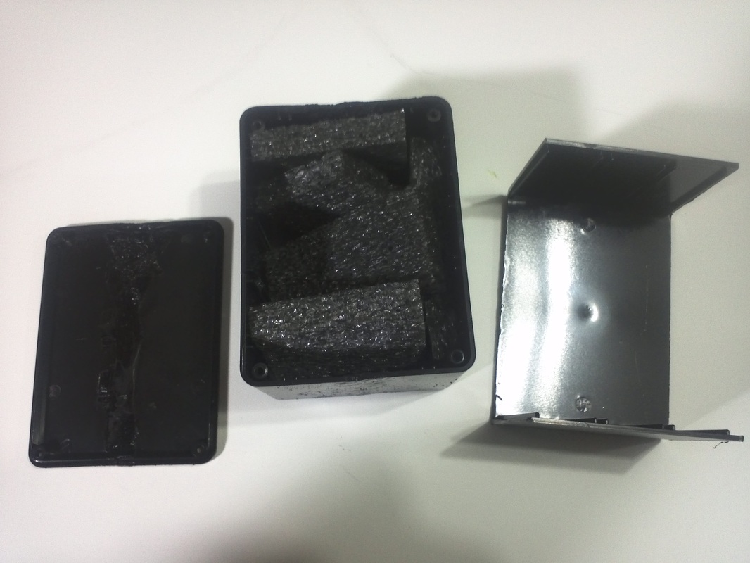
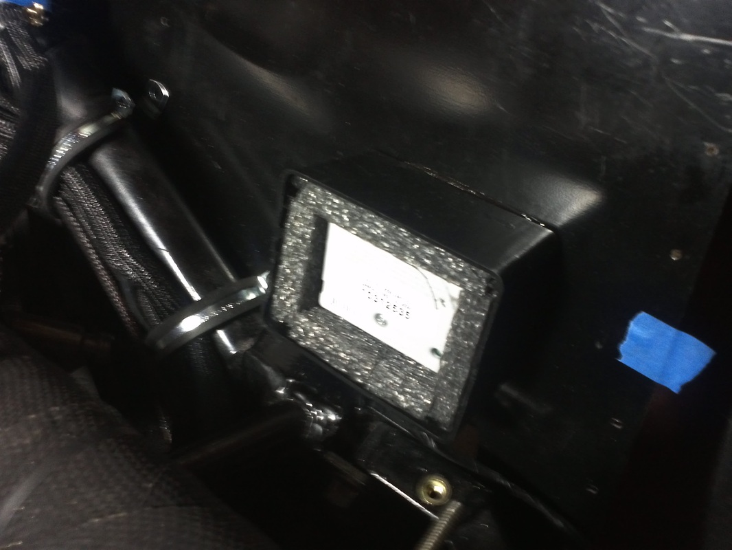
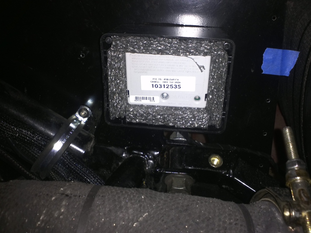
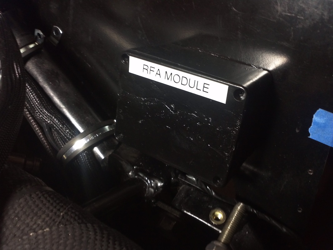
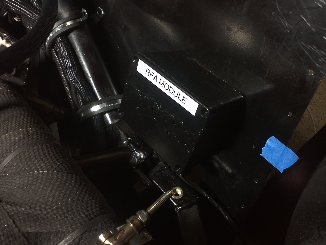
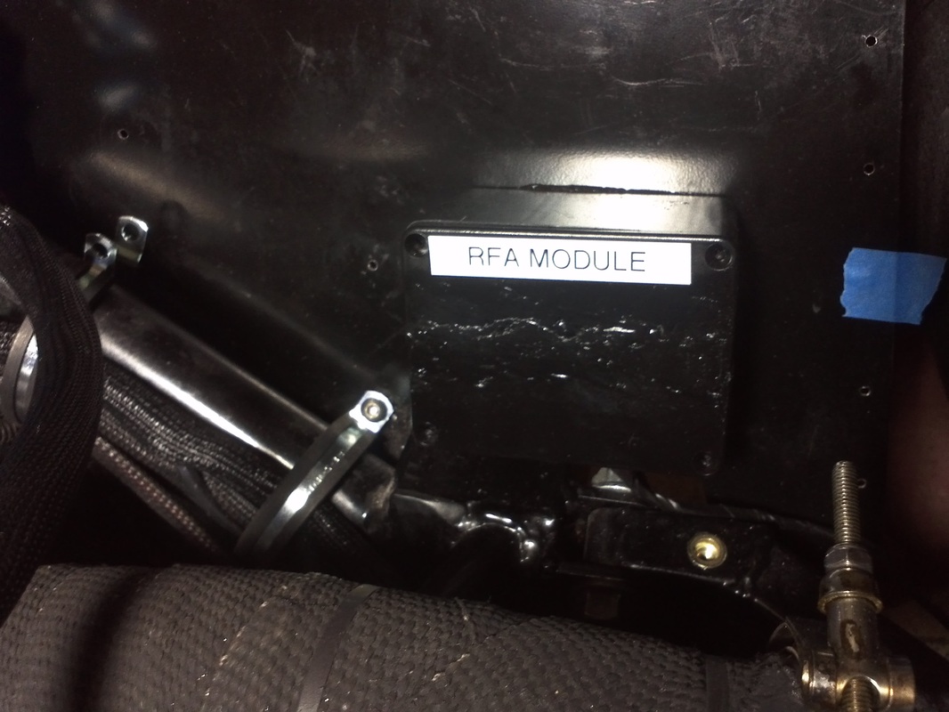
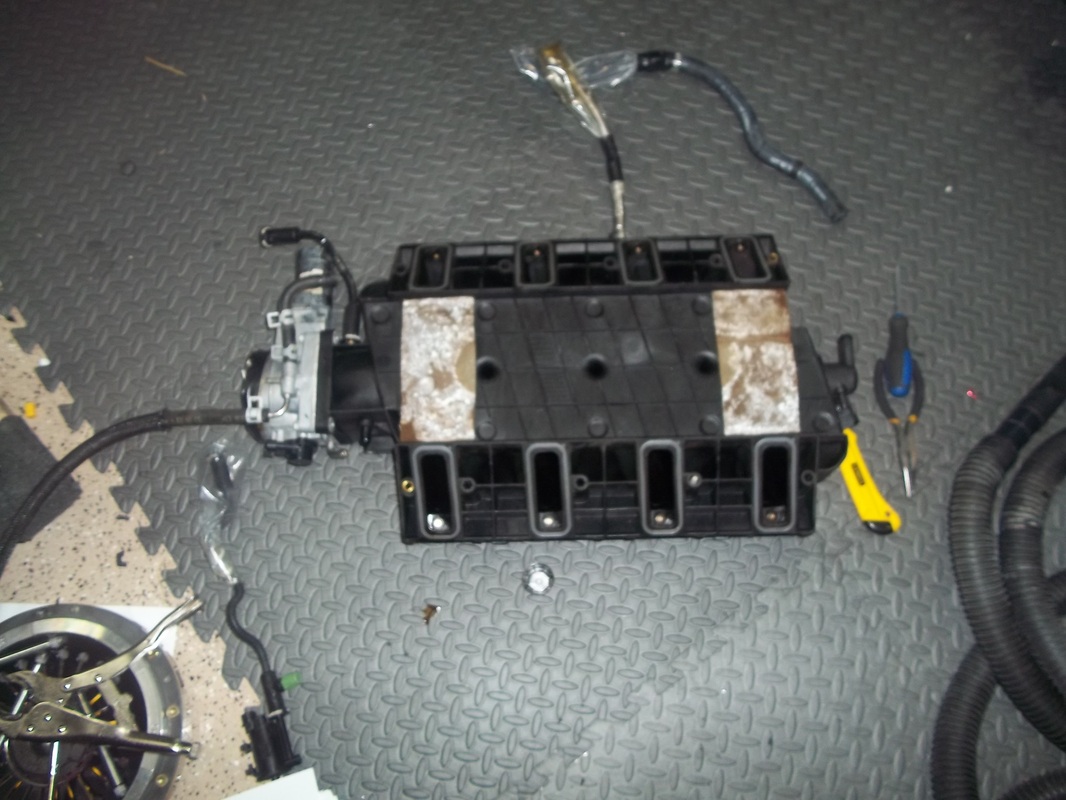
RFA Module Box
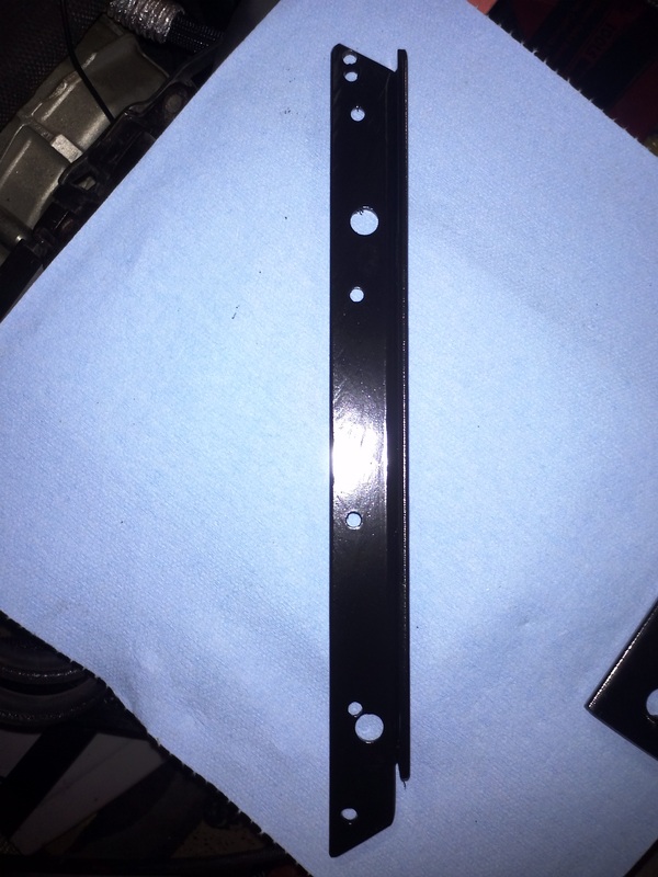
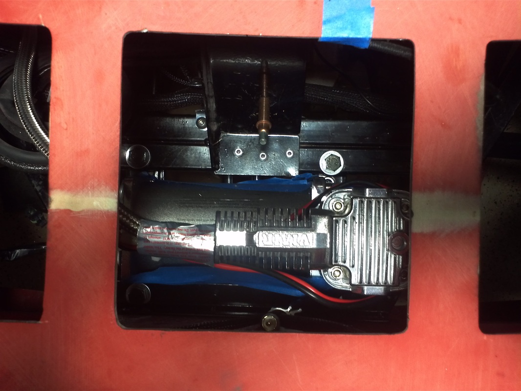
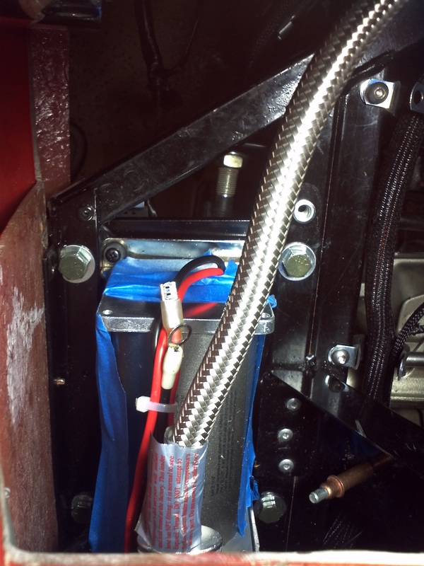
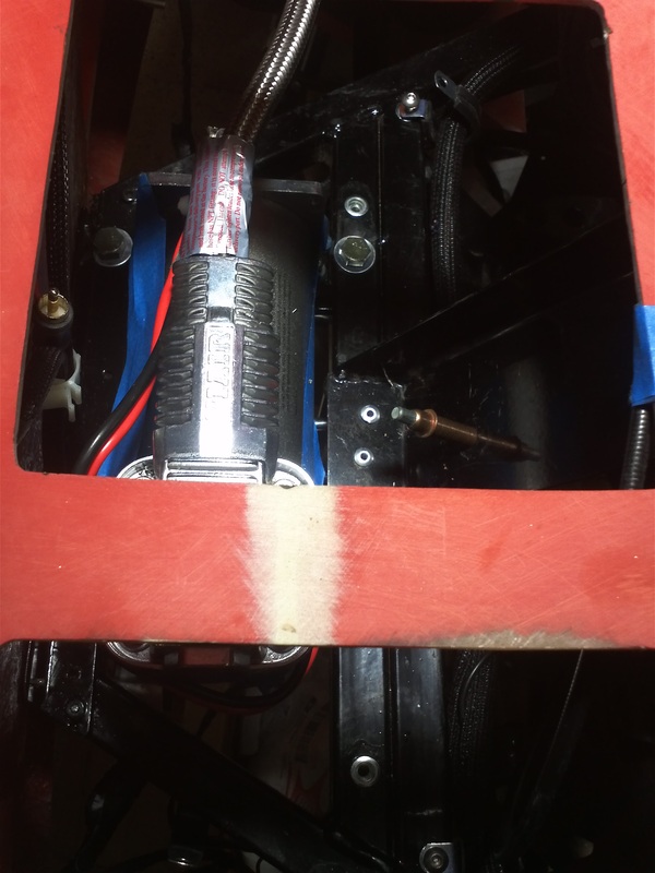
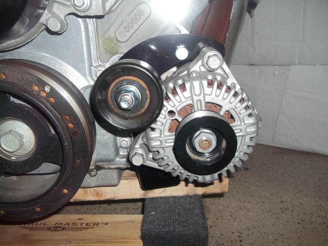
Lift Compressor Pump Mounting


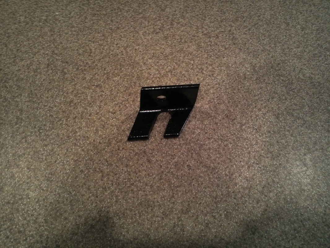
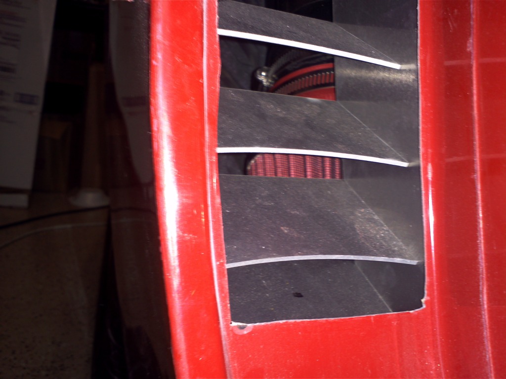
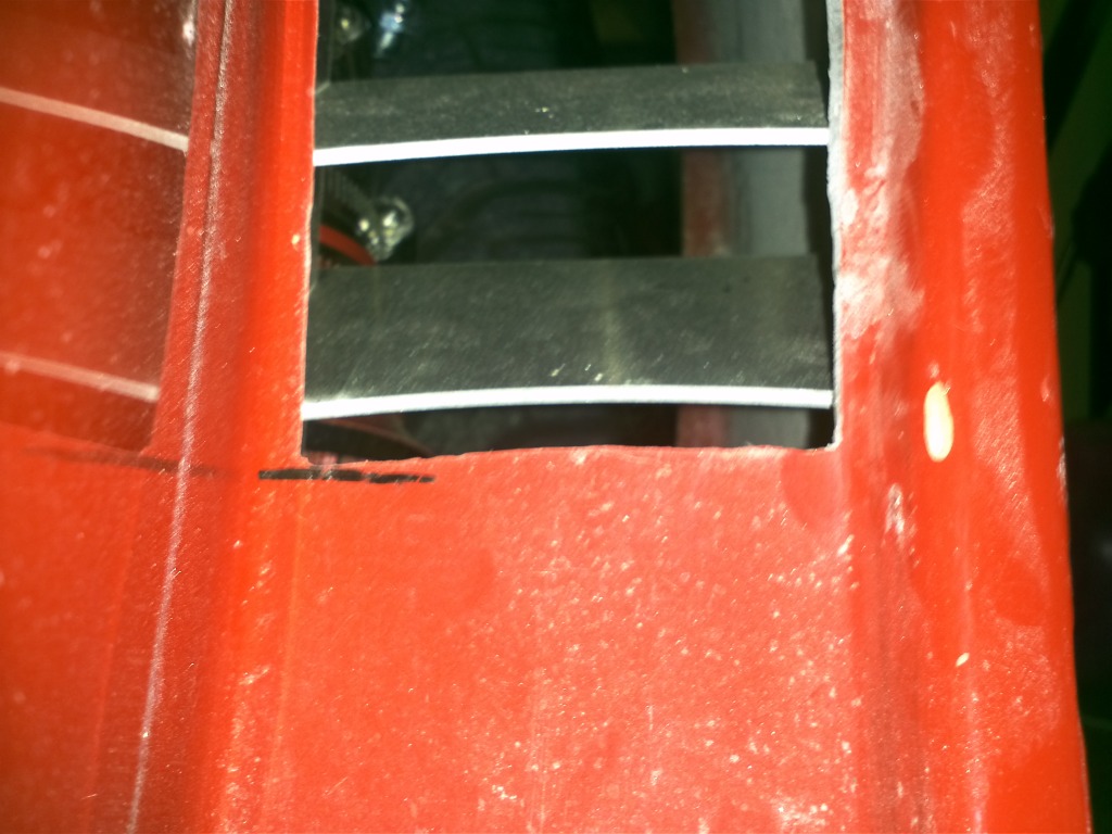
Hatch Light Mount/Louver


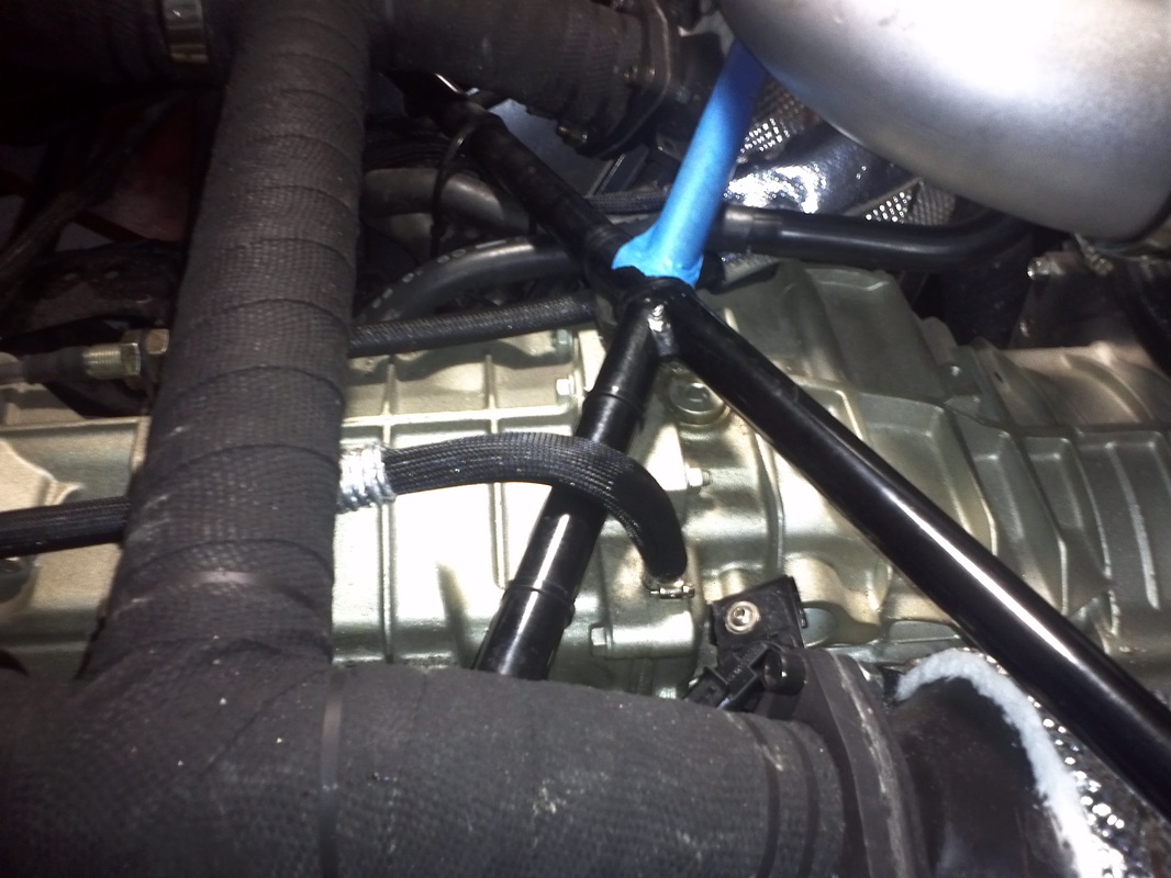
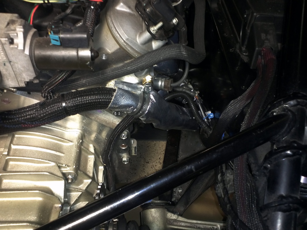
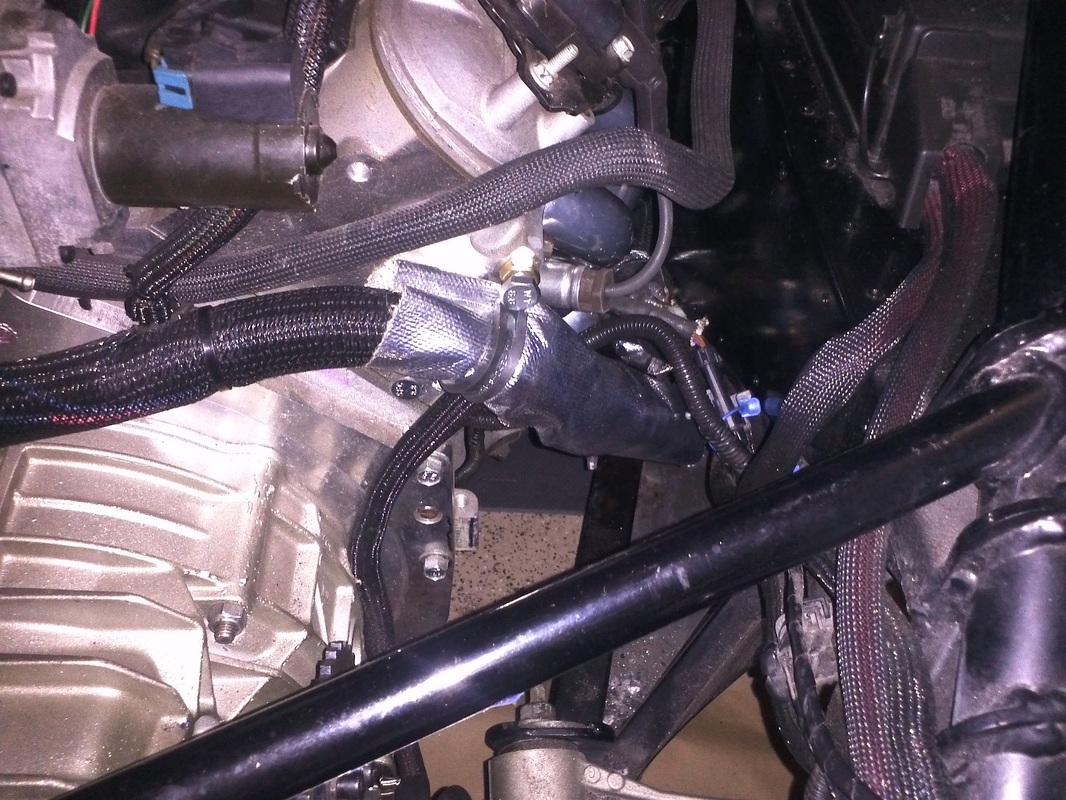
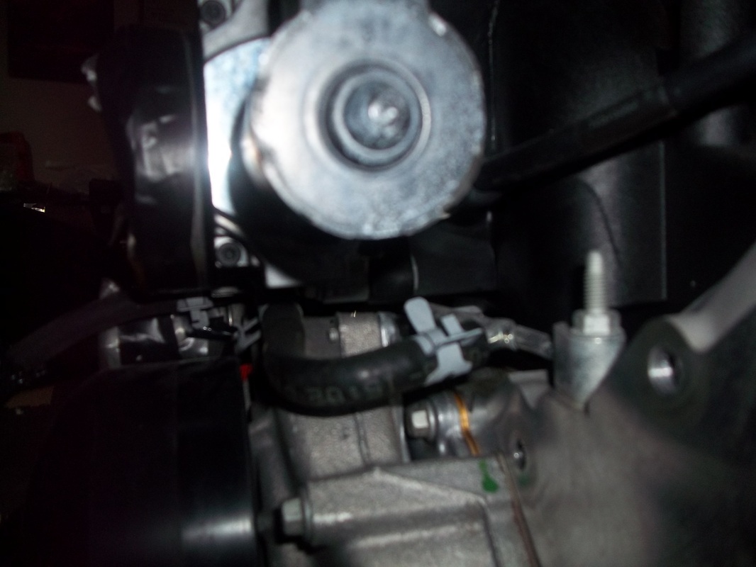
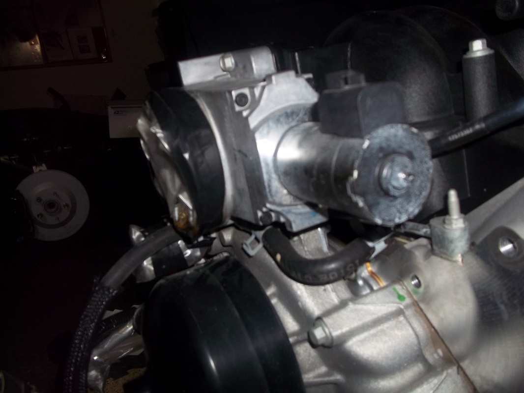
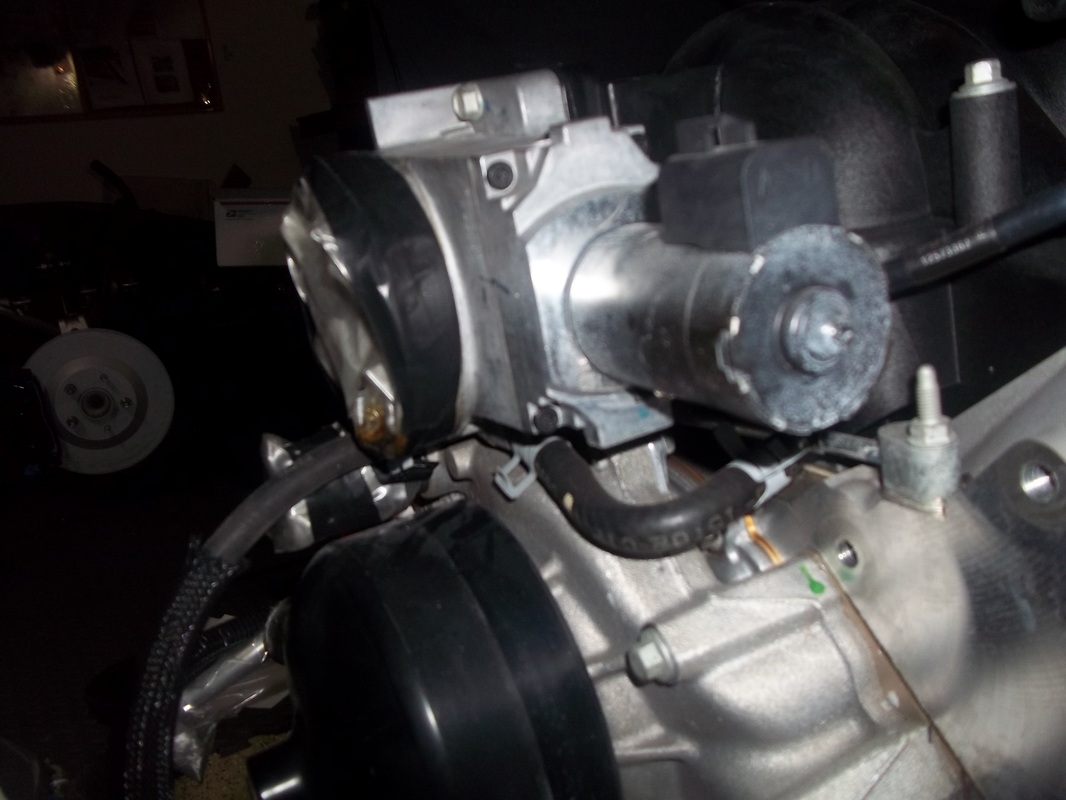
Transaxle Vent

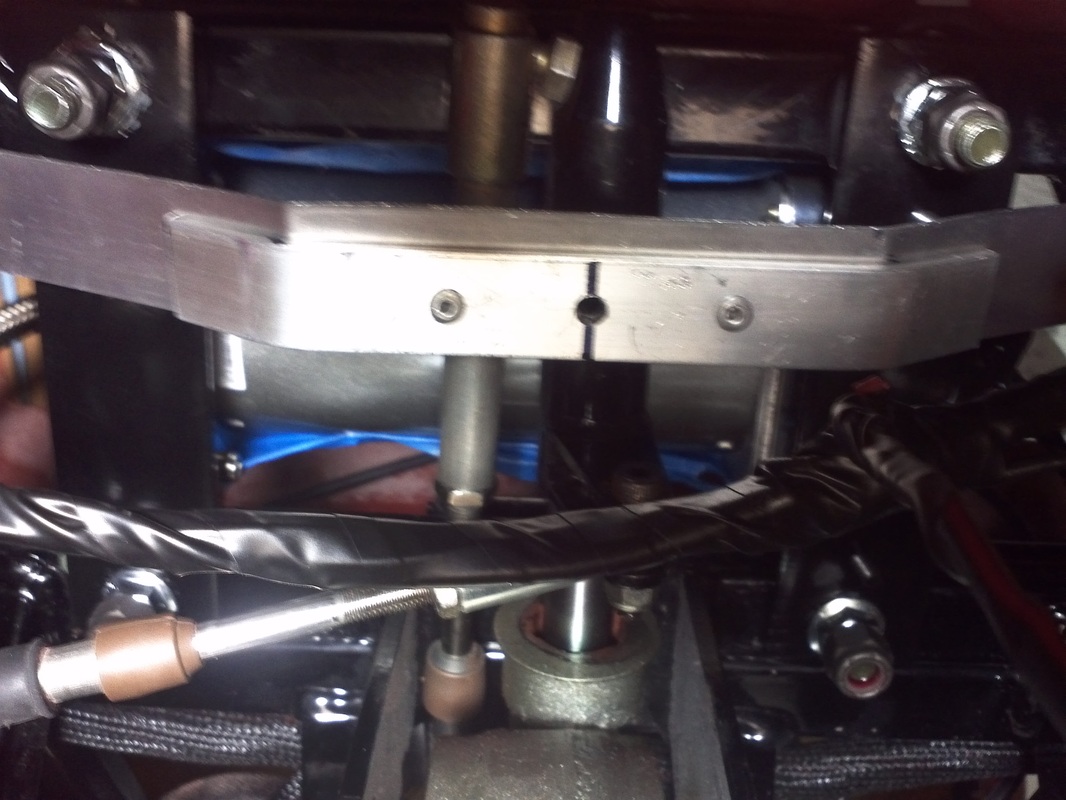
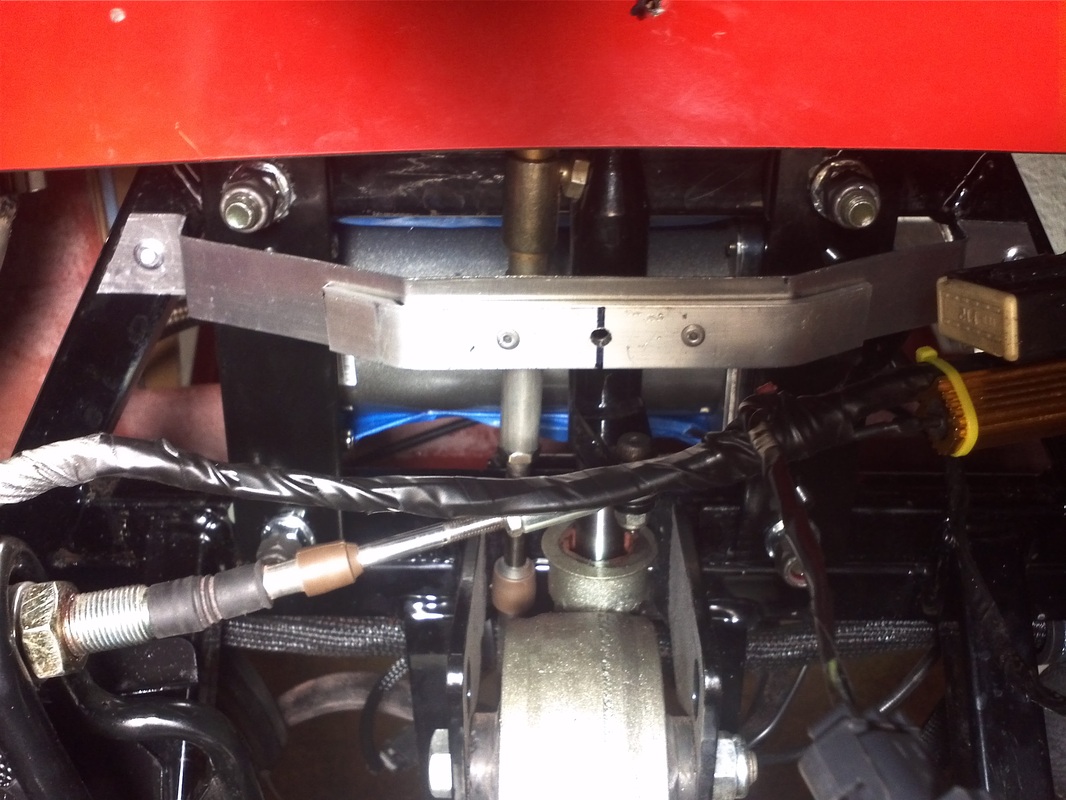
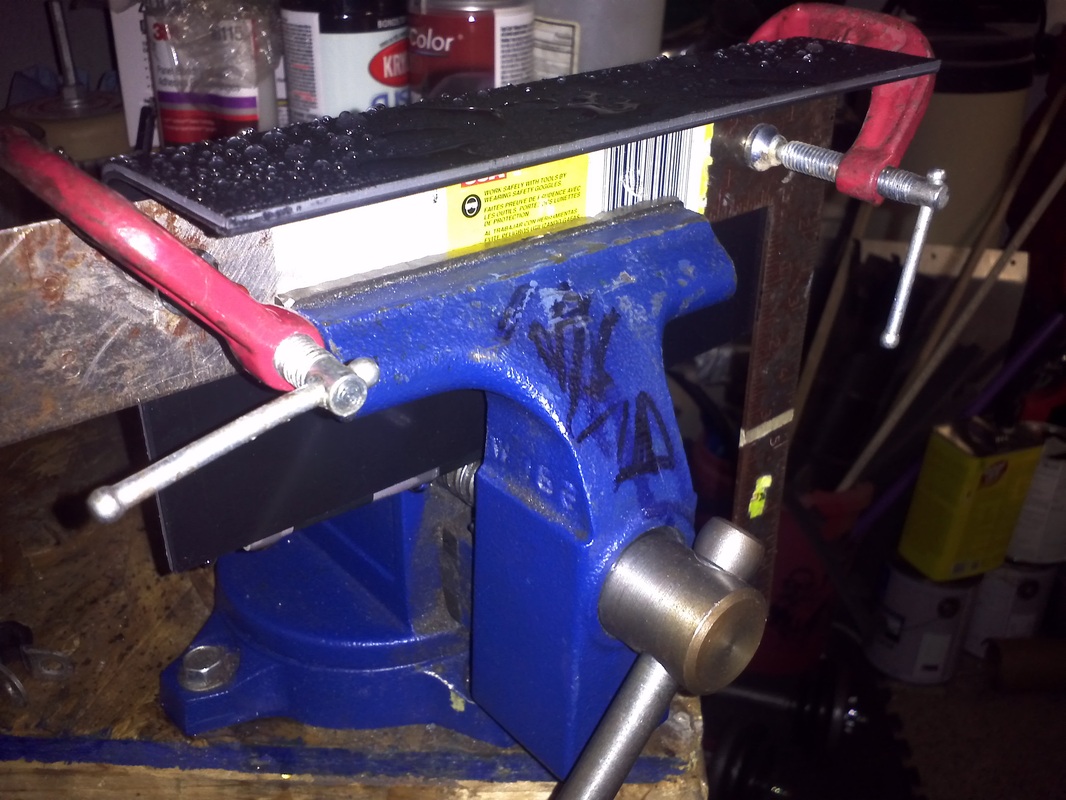
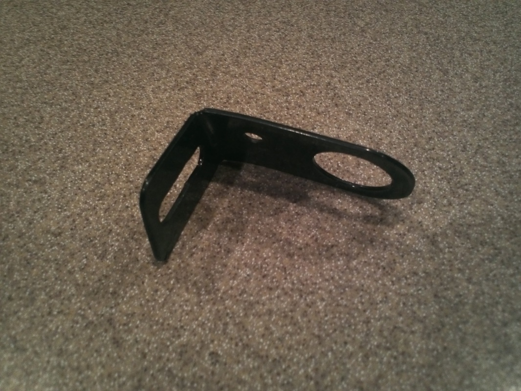
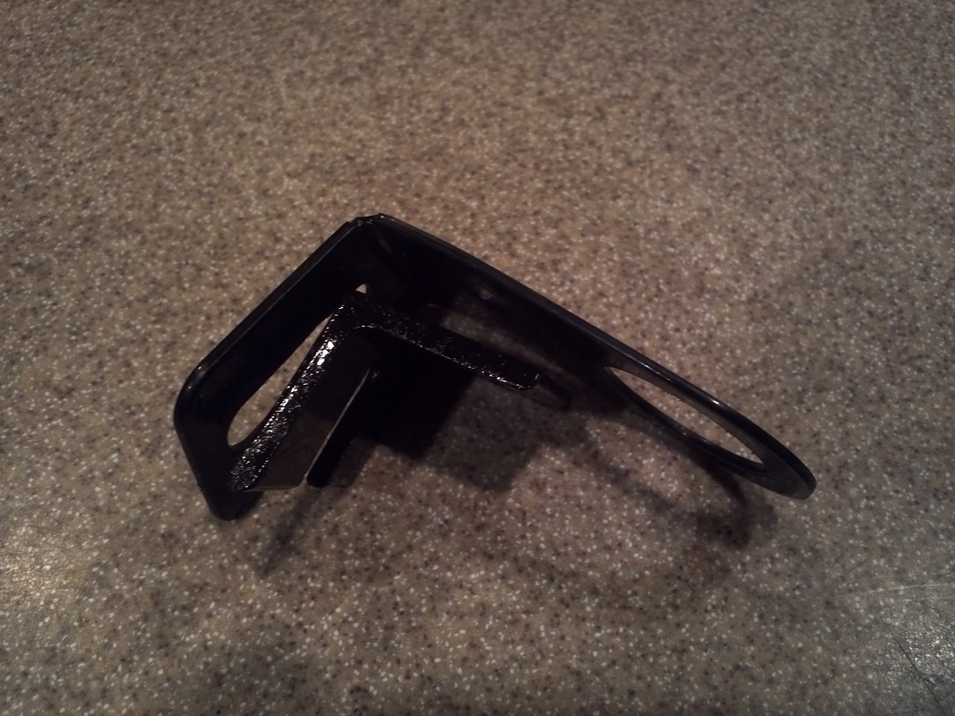
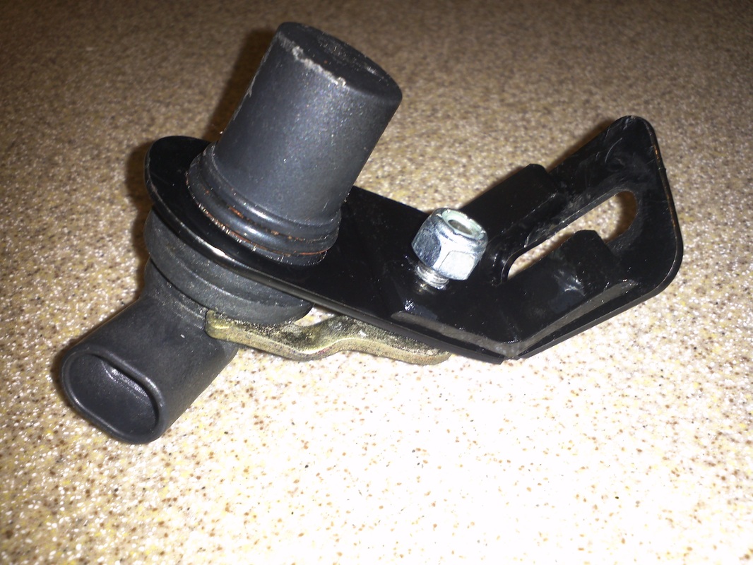
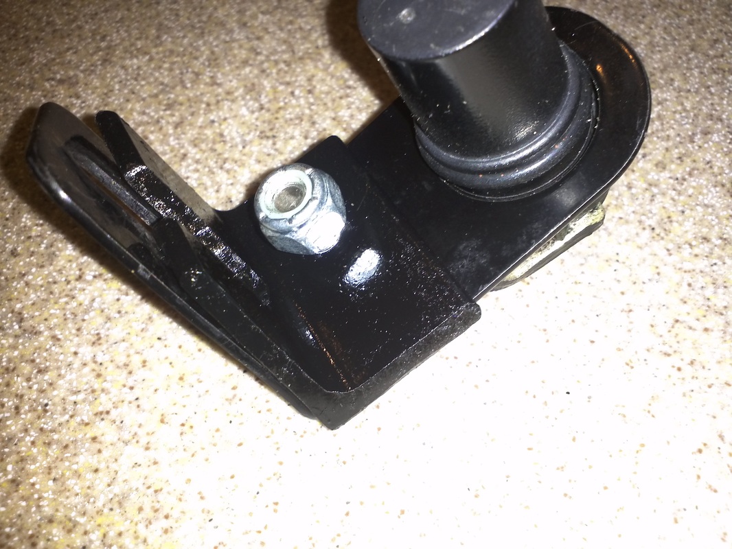
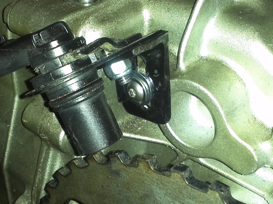
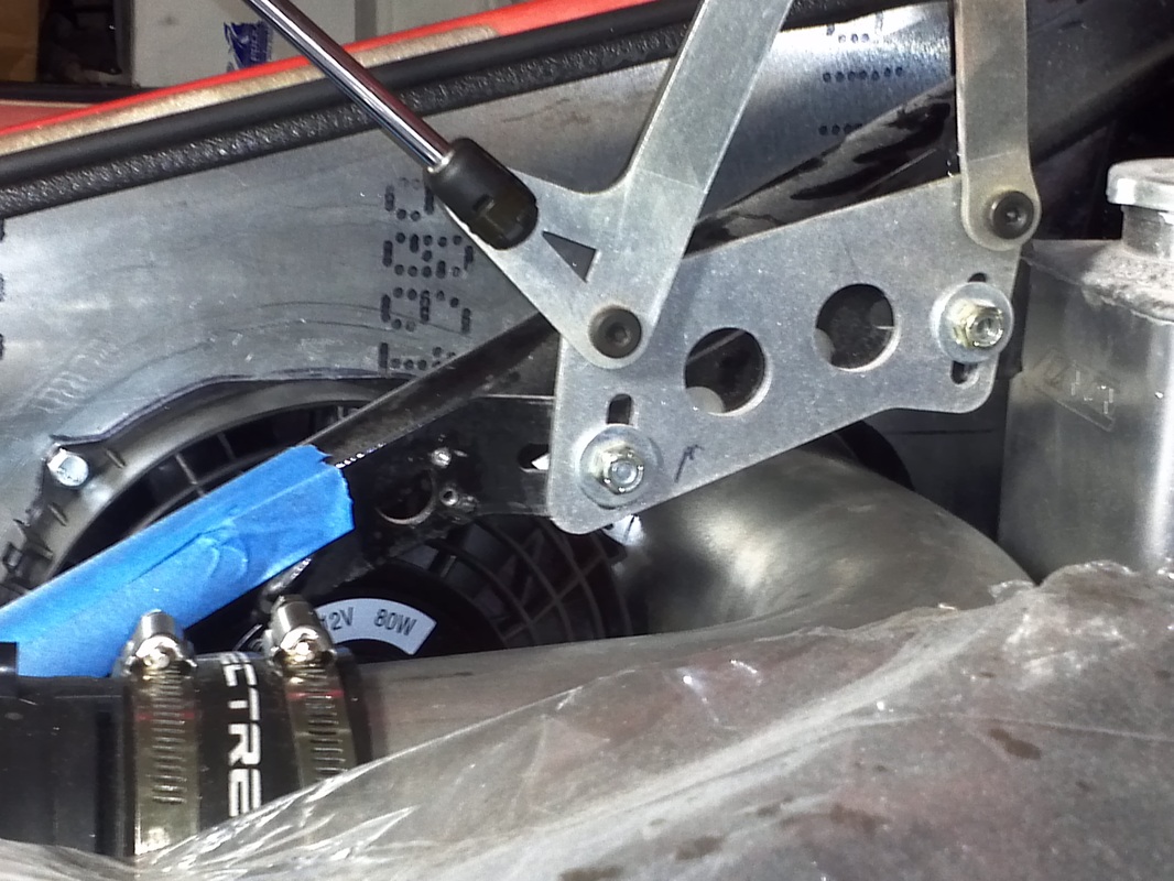
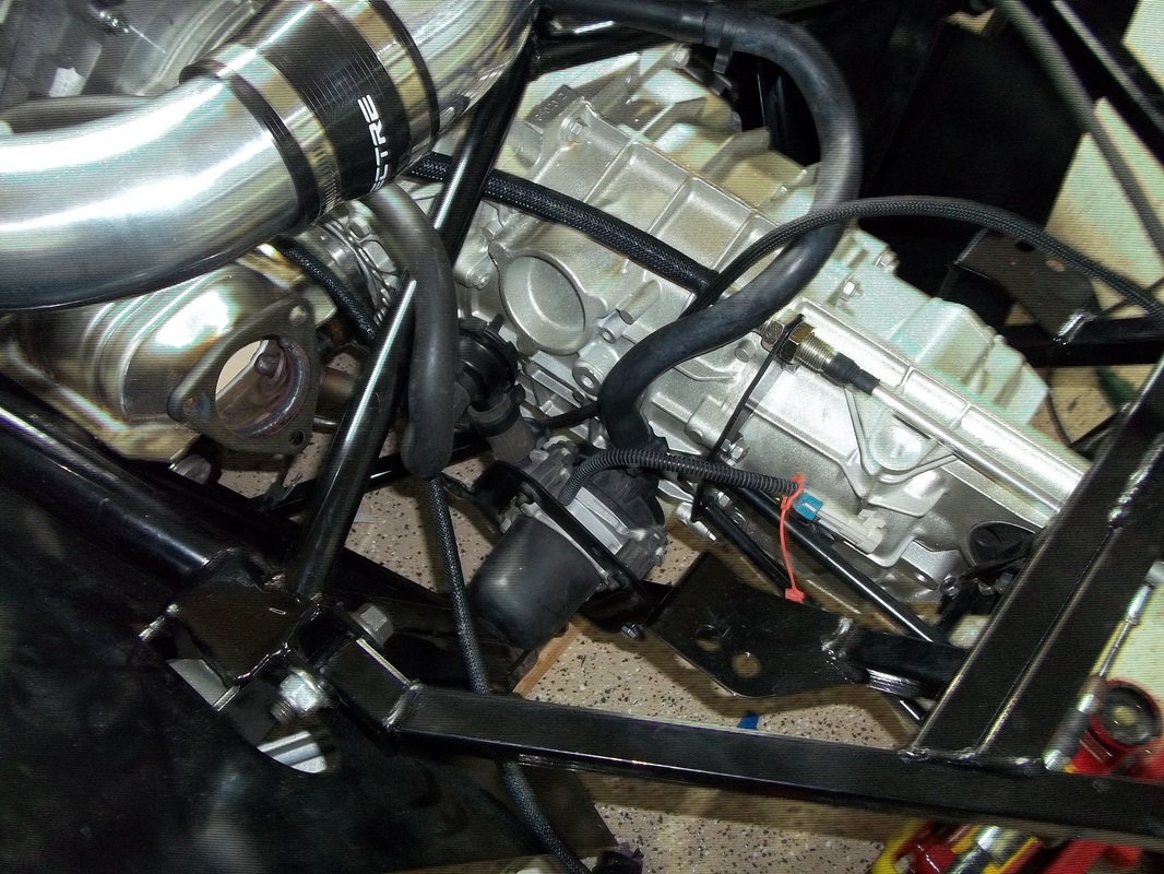
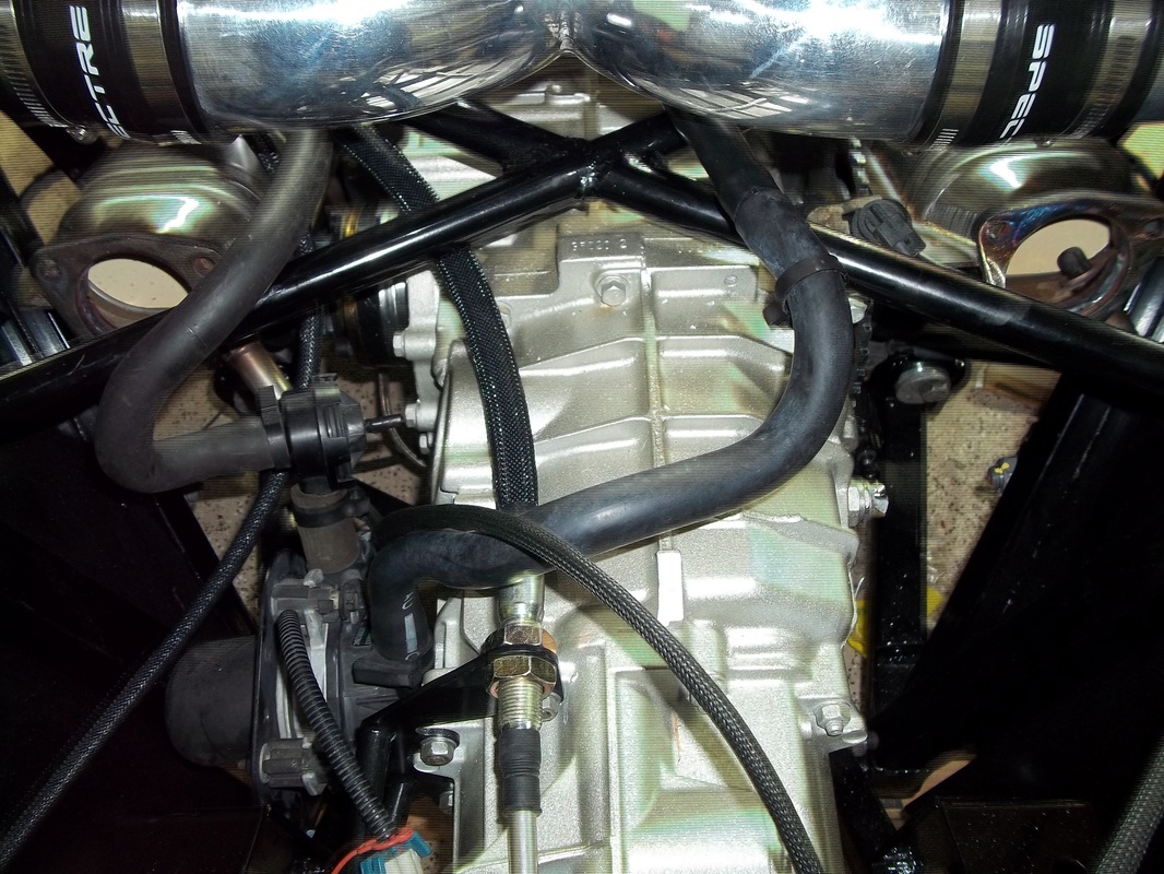
Vehicle Speed Sensor (VSS) Bracket Reinforcement
The kits bracket is thin and allows the sensor to move. I noticed that I would see the speedometer needle move while the GTM was idling. My initial thought was to weld on a triangle, then I came across some 1/8" angle while I was looking for some 16guage to weld. The angle sandwiches the bracket to the trans-axle and the VSS's bracket and results in a extremely solid mounting of the VSS.


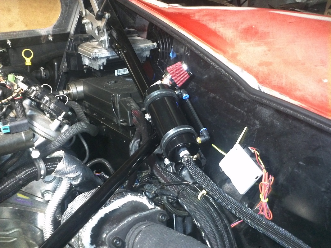
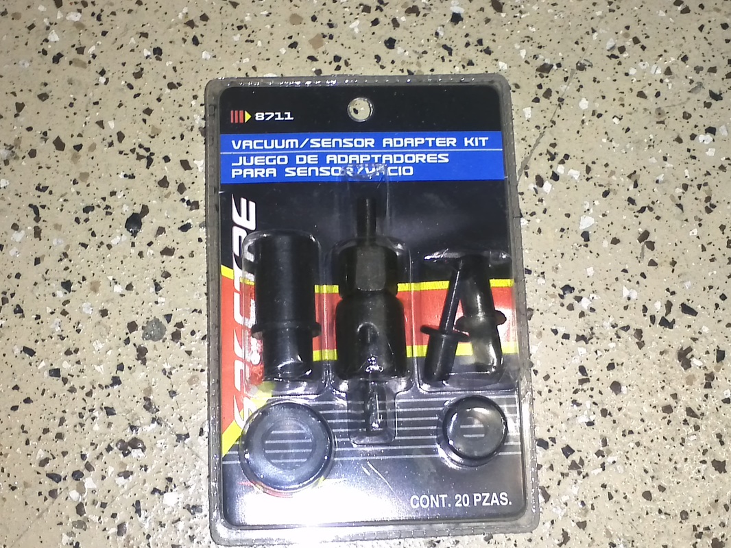
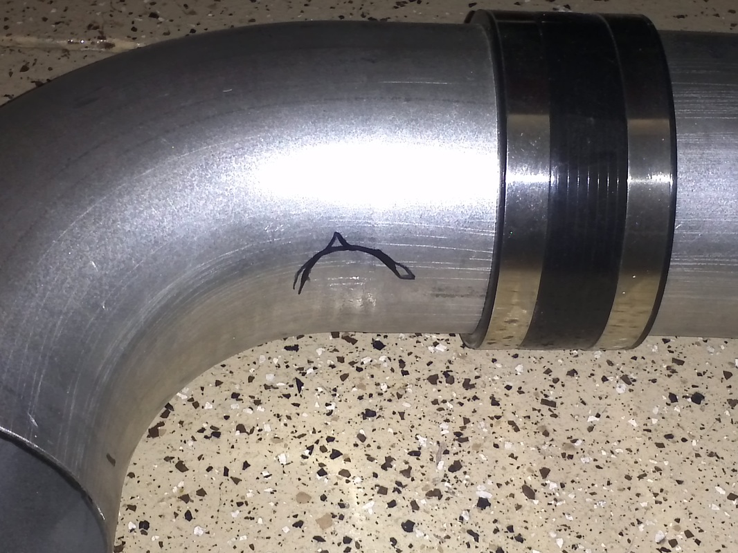
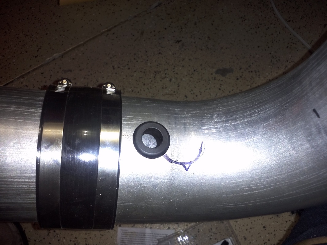
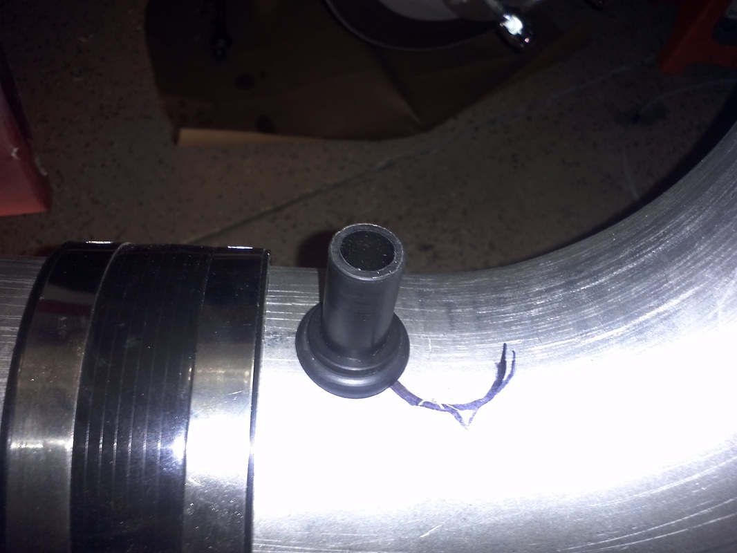
CAI Exhaust Gas Recirculation Adapter Install
I used the Spectre adapter kit to add the recirculation plug to my CAI. I need this connection because I have the full C5 emissions system installed. I drilled a 7/8" hole, installed the grommet and them inserted the the sized adapter.
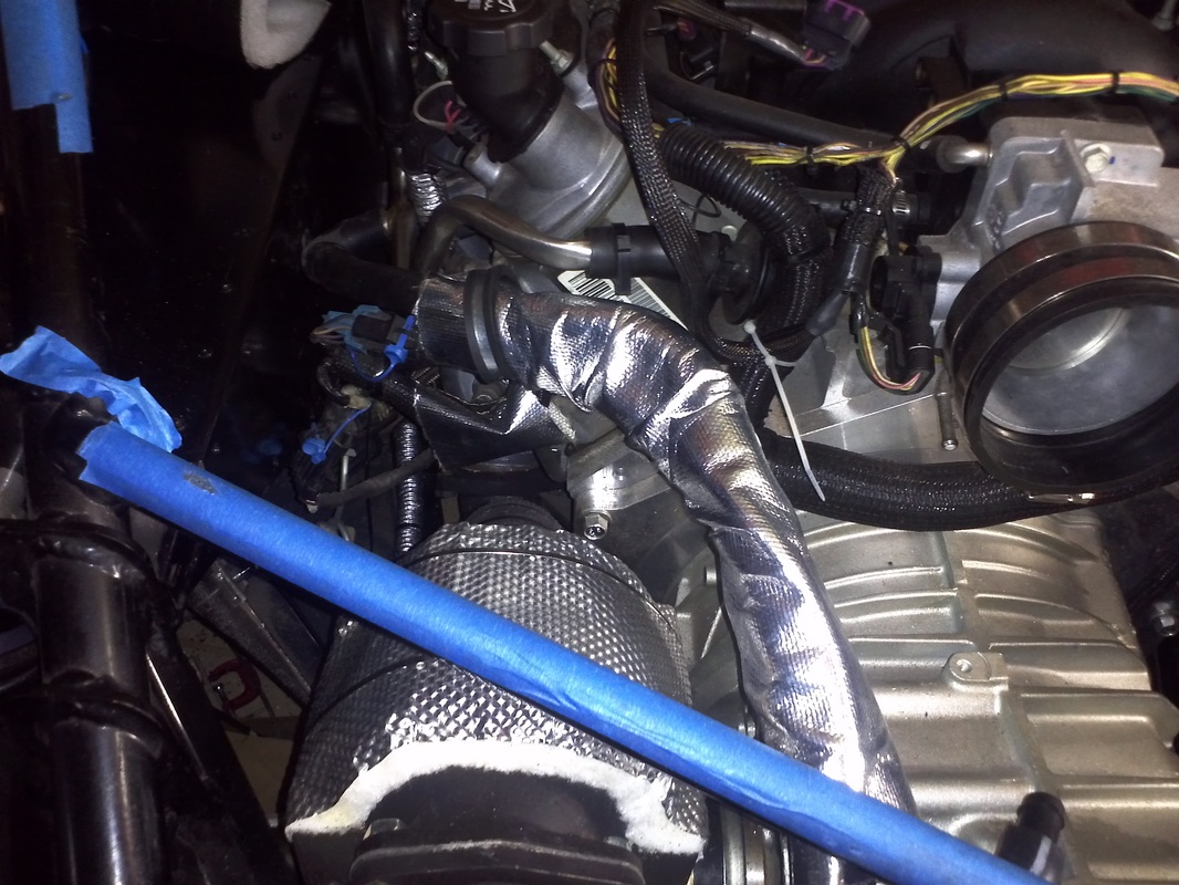
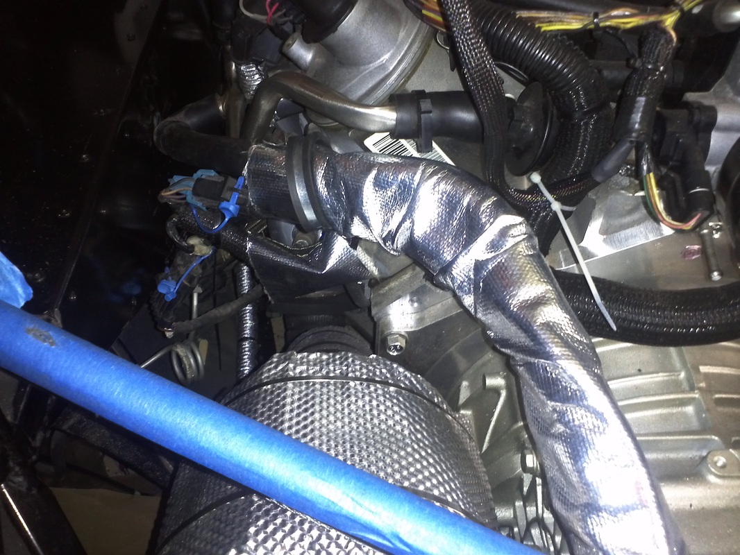
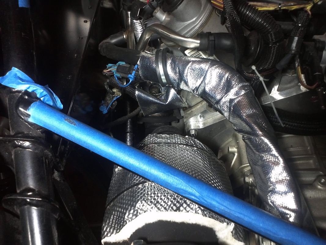
Some Heat Shielding
Protected the wires/hose that run the exhaust.
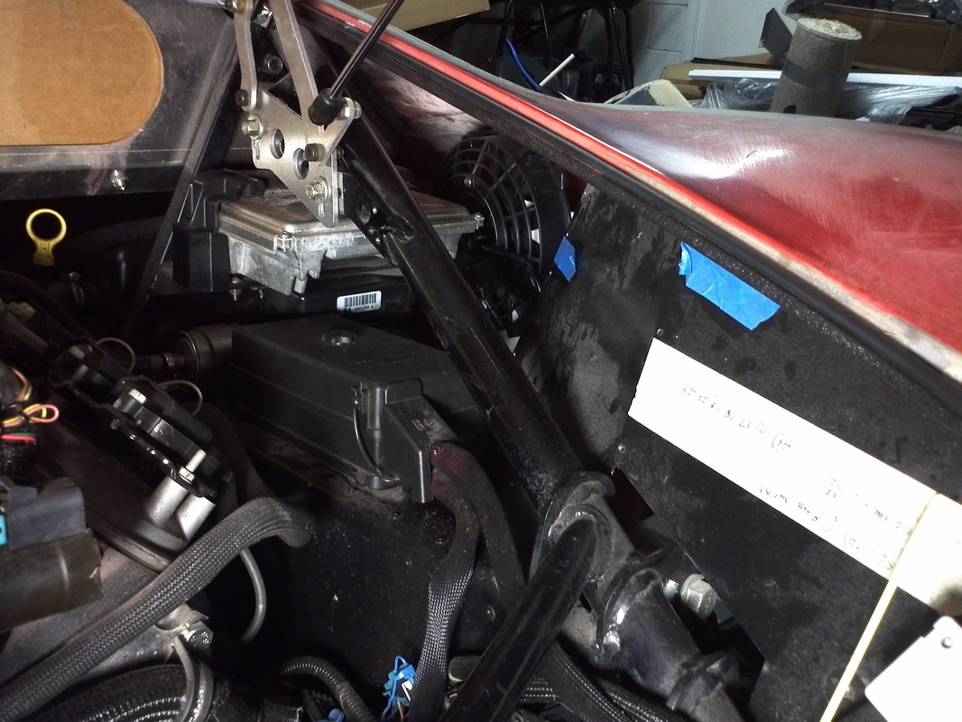
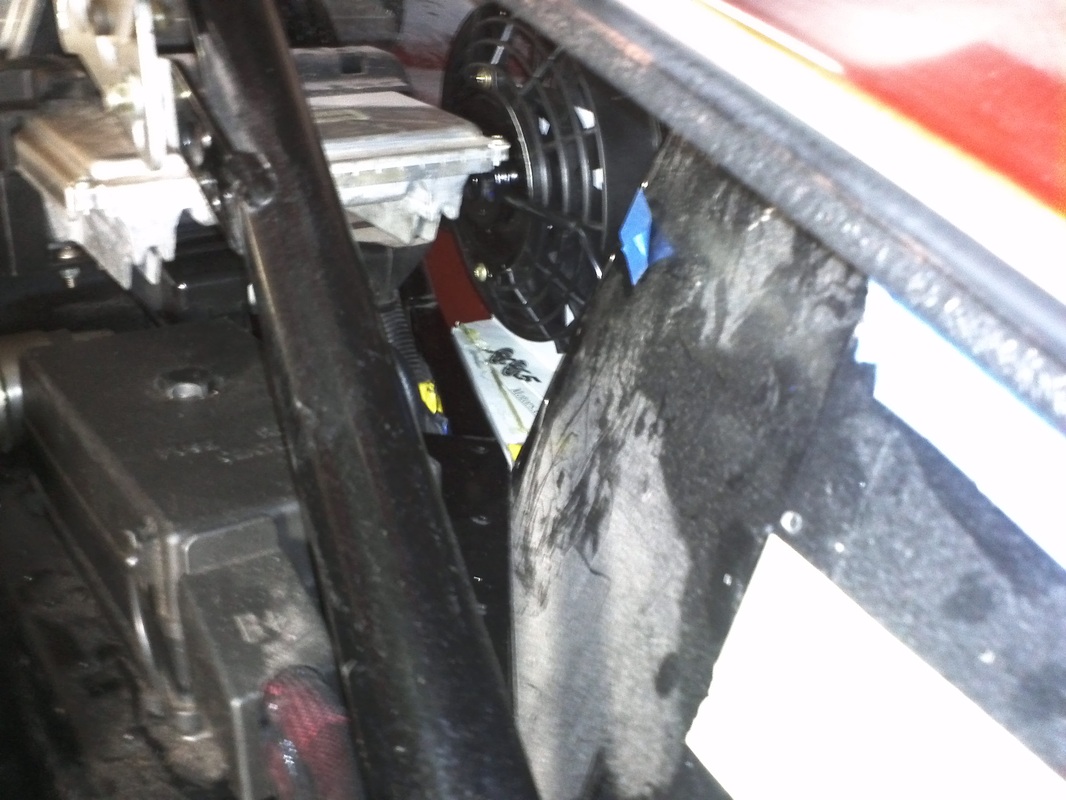
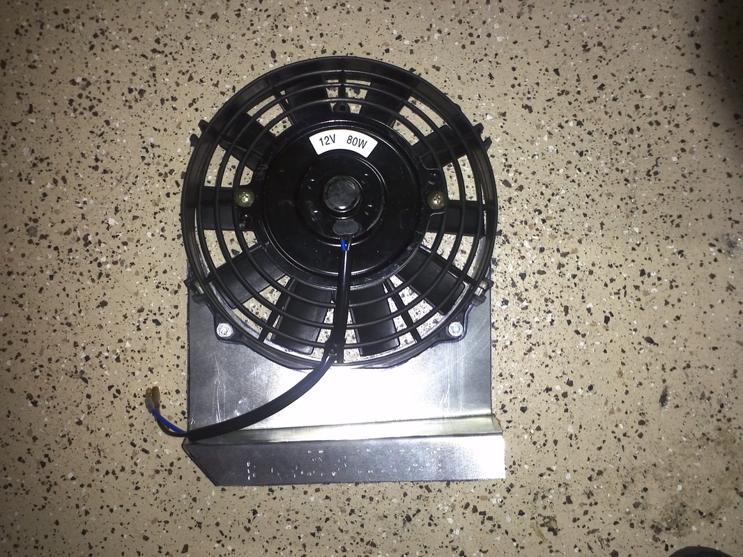
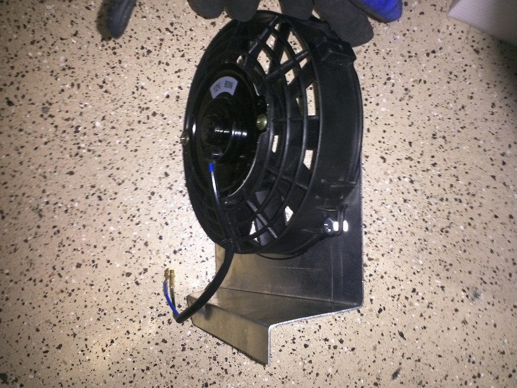
Fans
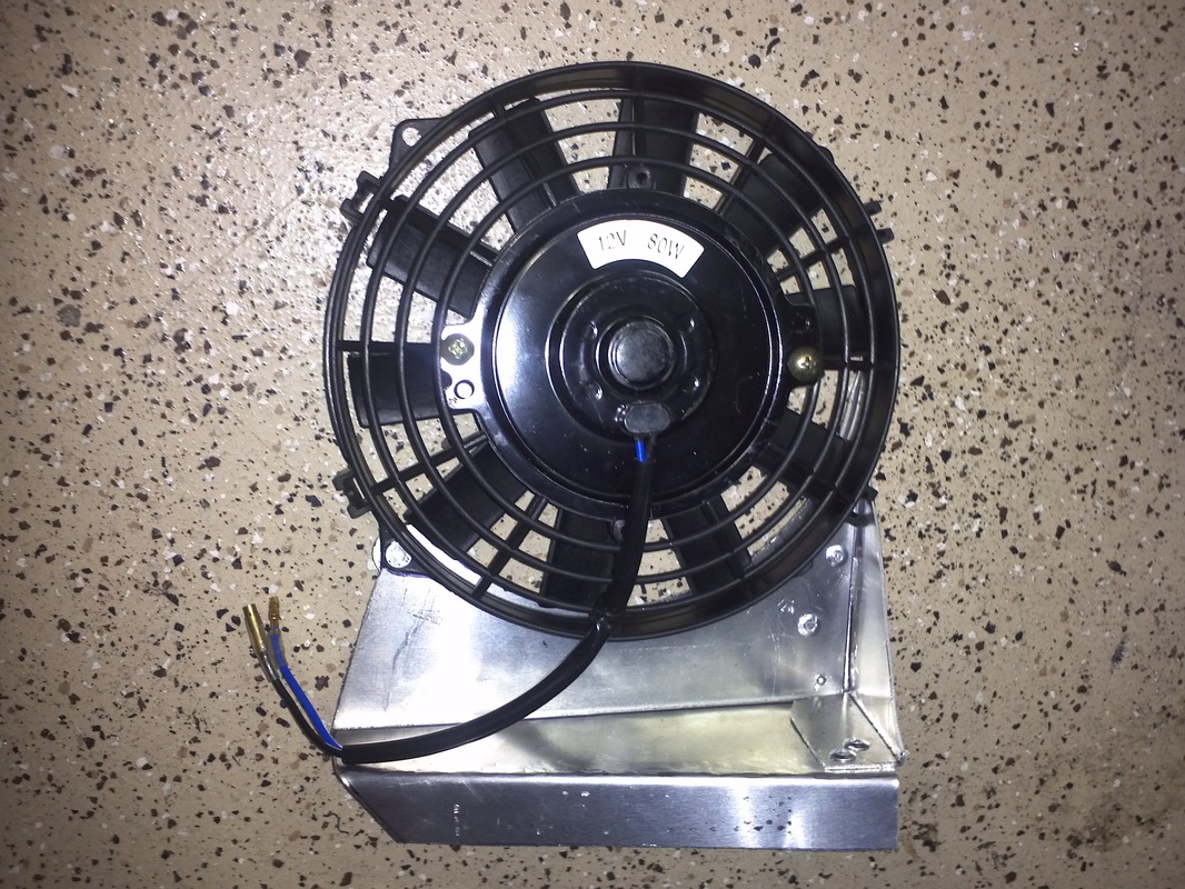
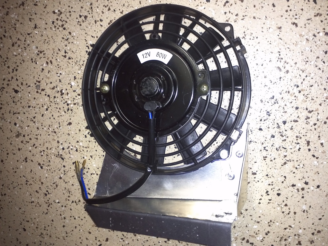
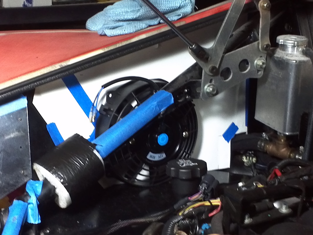
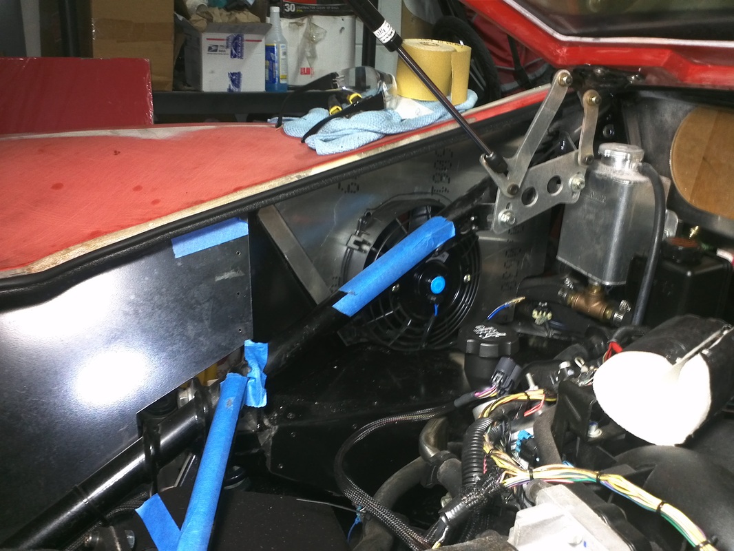
I've been planning to add two fans to the engine bay. The primary issue is that the heat builds and heats the firewall therefor transferring heat into the cockpit. I expect this is not an issue when the vehicle is moving fast enough for adequate air movement. I want to use two 1000 cfm fans and the tunnel fan to move air based on the ambient temperature in the top area of the engine bay.
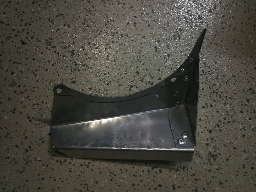
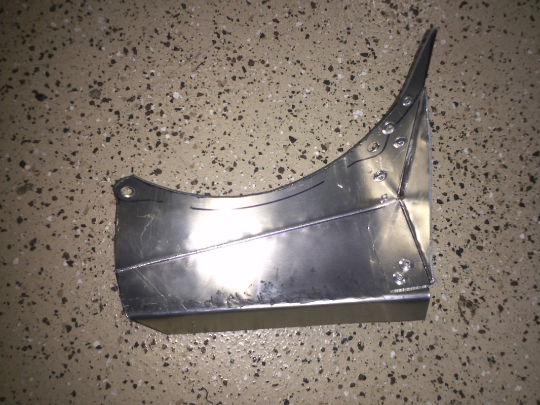
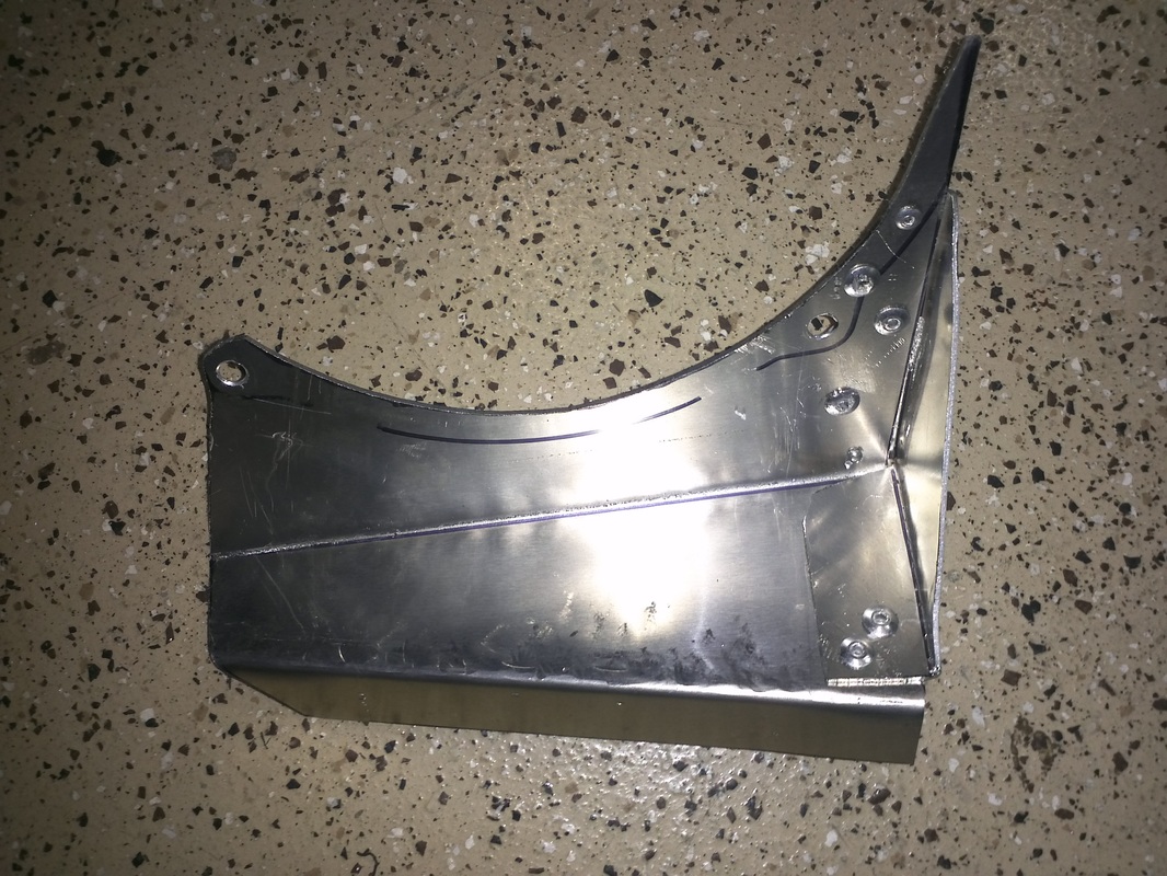
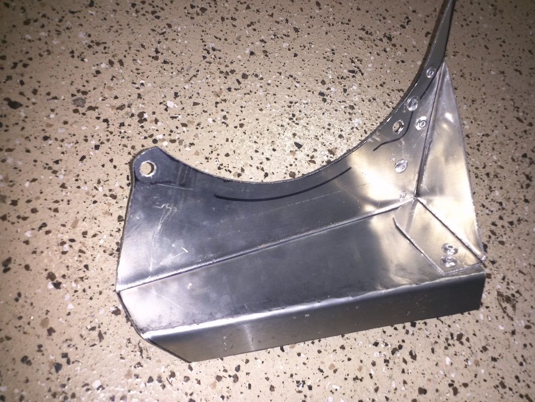
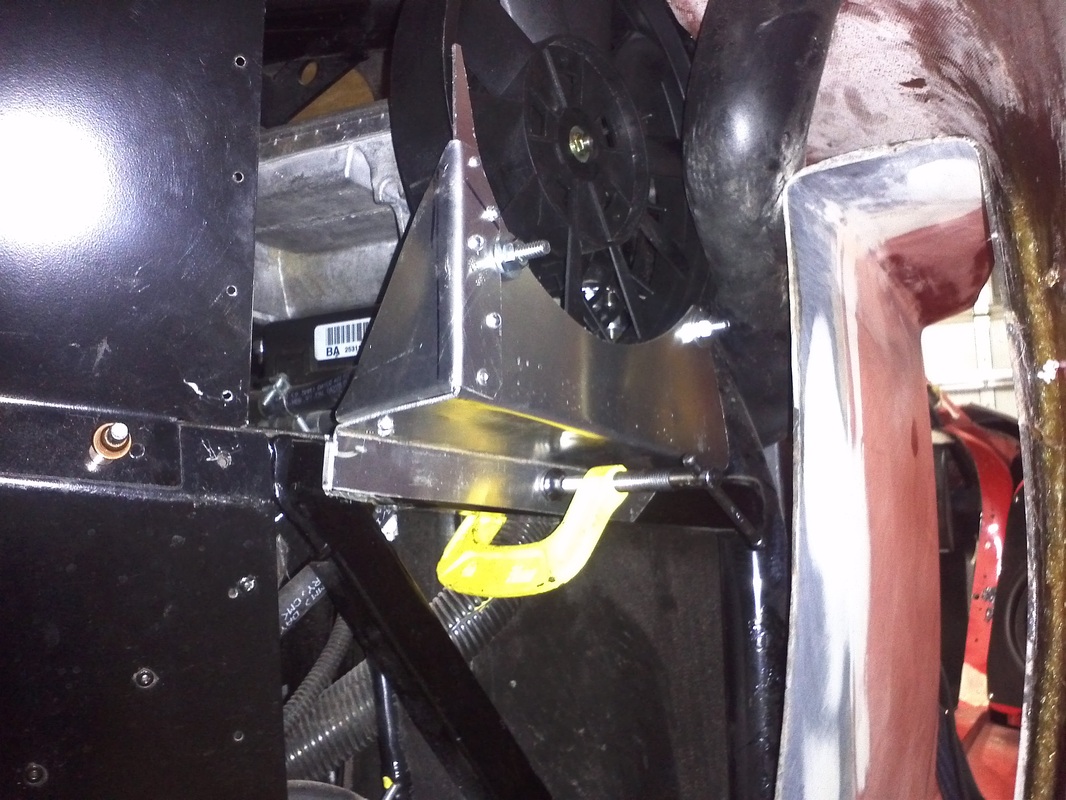
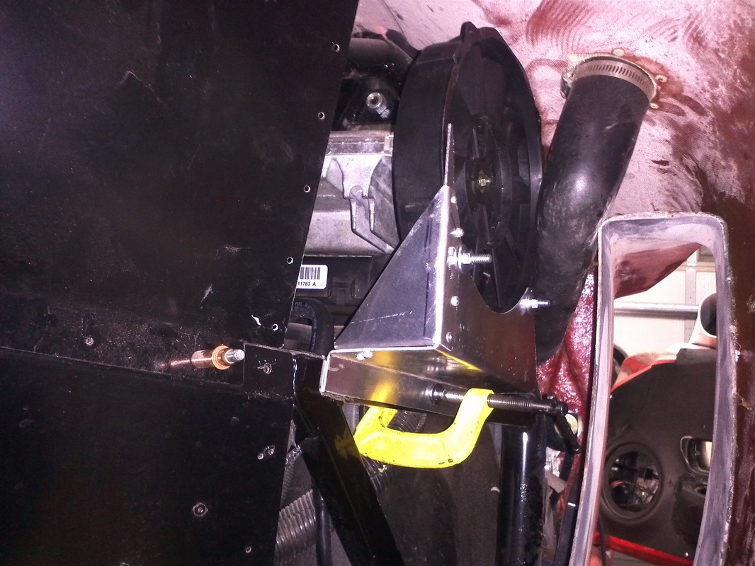
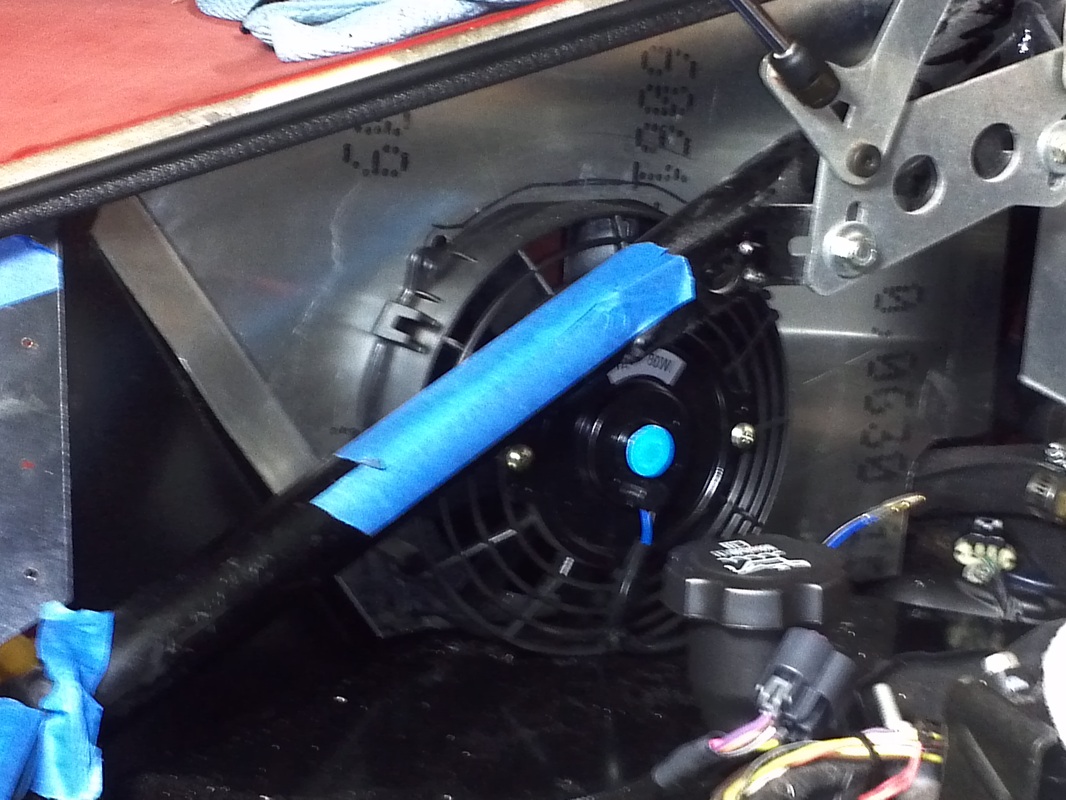
The RH side will be on a bracket with a very open install. This should allow almost as much airflow from my full open side engine bay air scoop and provide enough differential to pull in air when it is in operation.
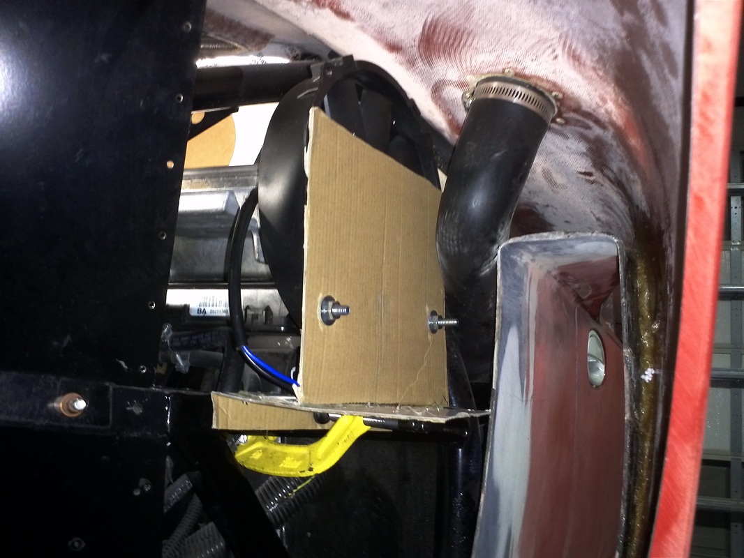
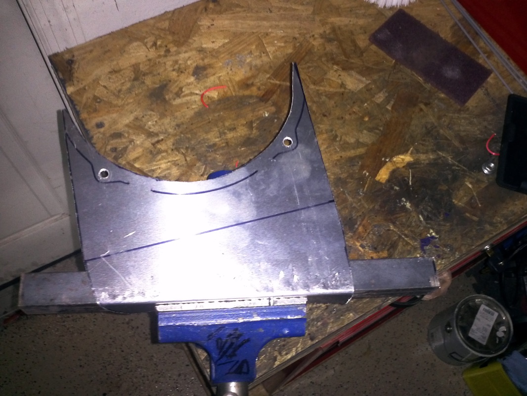
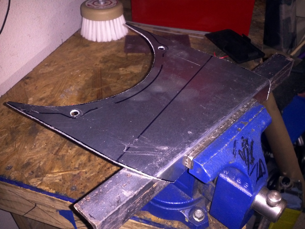
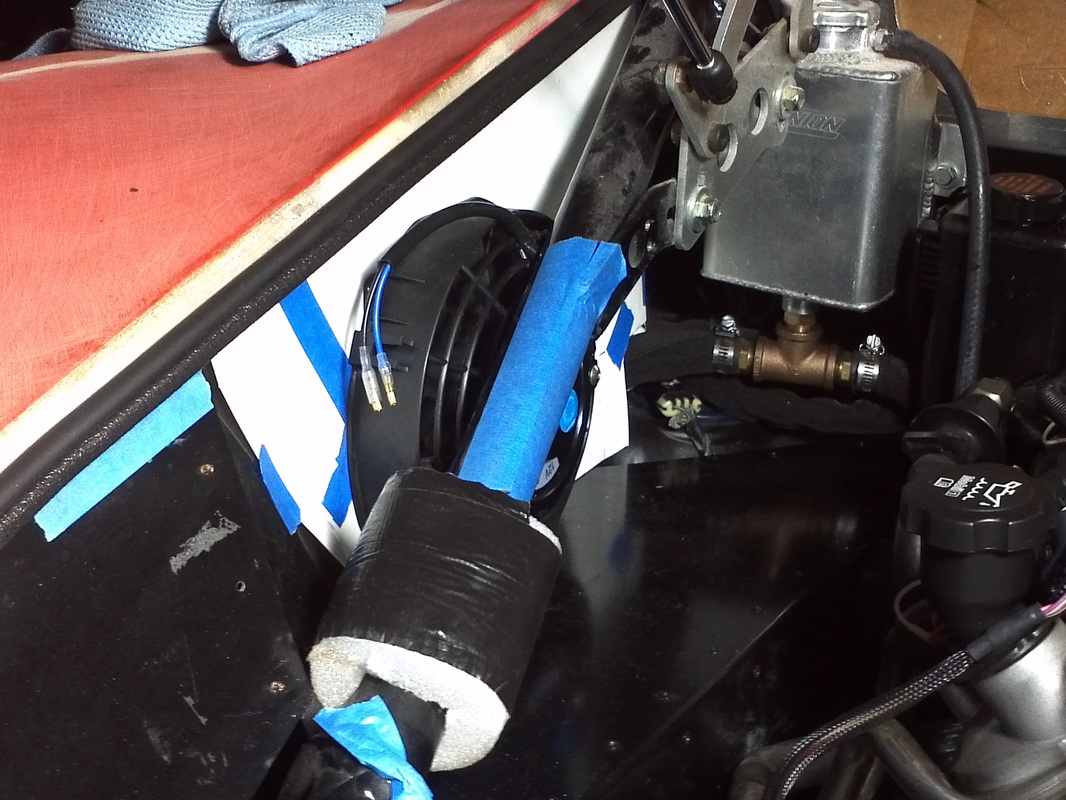
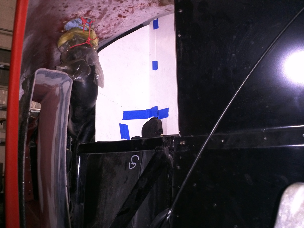
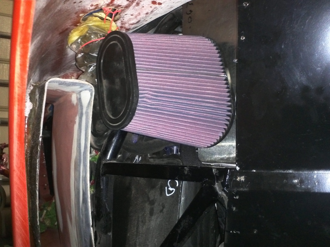
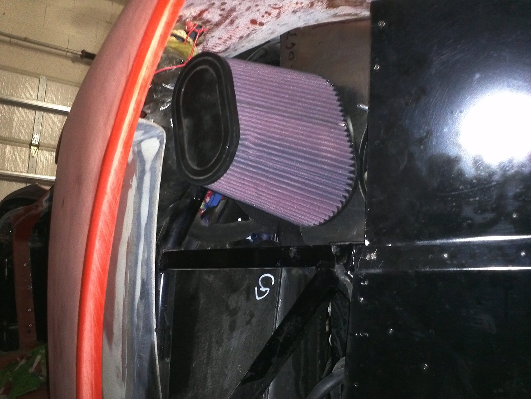
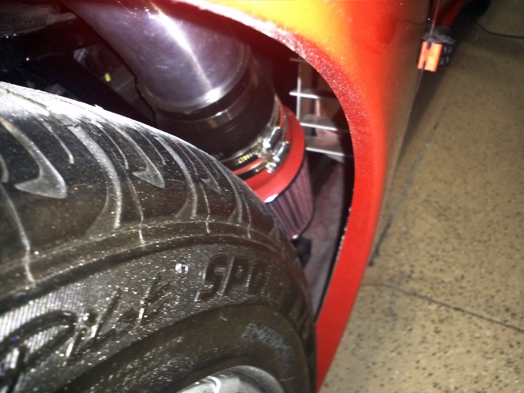
The LH side gets a more substantial separation. The mount will double as an air filter, air box insulated wall. The panel is going to take up approximately 80% of the area above the fuel tank. The fan and the area to the front of the panel are the only upper open areas. Outside of the panel It is not a 100% isolation because the side of the fuel tank is open to the side scoop area. The panel will be covered with HeatShield Lava Shield.
The RH side will be on a bracket with a very open install. This should allow almost as much airflow from my full open side engine bay air scoop and provide enough differential to pull in air when it is in operation.
The LH side gets a more substantial separation. The mount will double as an air filter, air box insulated wall. The panel is going to take up approximately 80% of the area above the fuel tank. The fan and the area to the front of the panel are the only upper open areas. Outside of the panel It is not a 100% isolation because the side of the fuel tank is open to the side scoop area. The panel will be covered with HeatShield Lava Shield.
RH side
|
LH Side
|
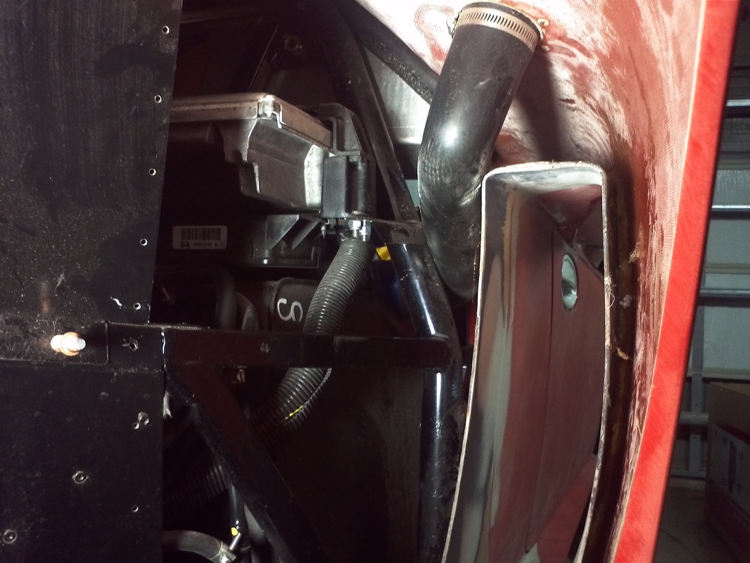


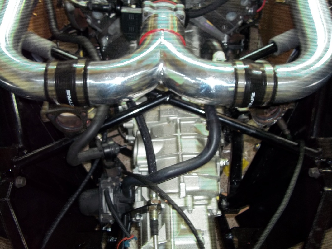
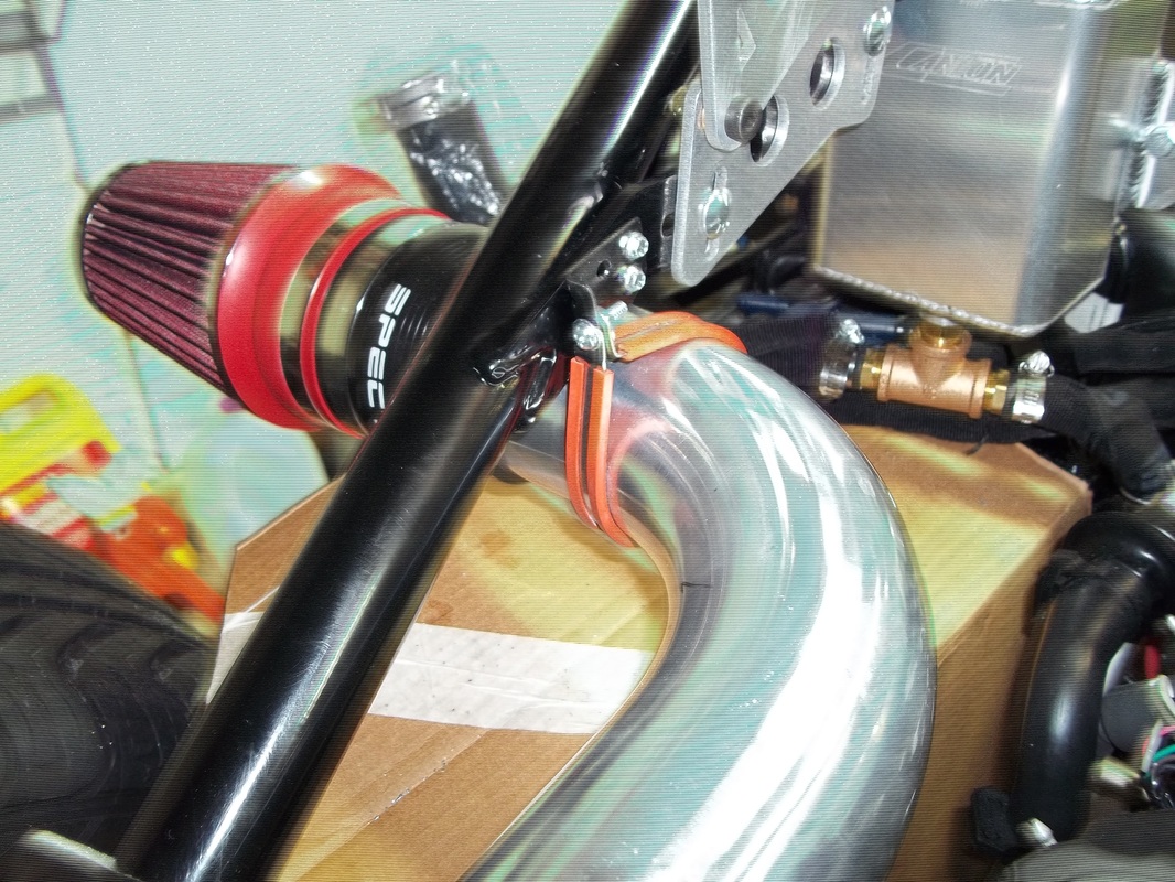
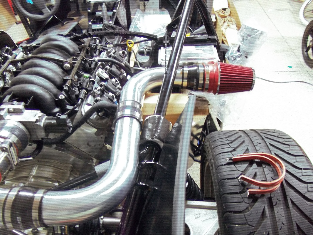
Single 4" CAI. (CAI #2)
I've been doing some study on tuning. In order to optimize my setup I am moving to a single 4" CAI in line with the GM LS crate engine Mass Air Flow (MAF) sensor install instructions.
“The induction system should be 4 inches in diameter and
have a minimum straight section 6 inches in length. Mount the MAF sensor in the
middle of the straight induction section, ensuring that the middle of the
mounting boss is at least 10 inches from the throttle body.”
With my current dual filter set up the MAF sensor is ~3" from the throttle body. My donor's MAF is the smaller (74.5mm) which doesn't match my 2003 LS6. The 85mm MAF was used in the C5 Z06. This is also the reason I am getting intermitant misfires (DTC P0300) and fuel trim system lean bank 1 and 2 (DTC's P0171 and P0174). These trouble codes can be remedied with a tune also.
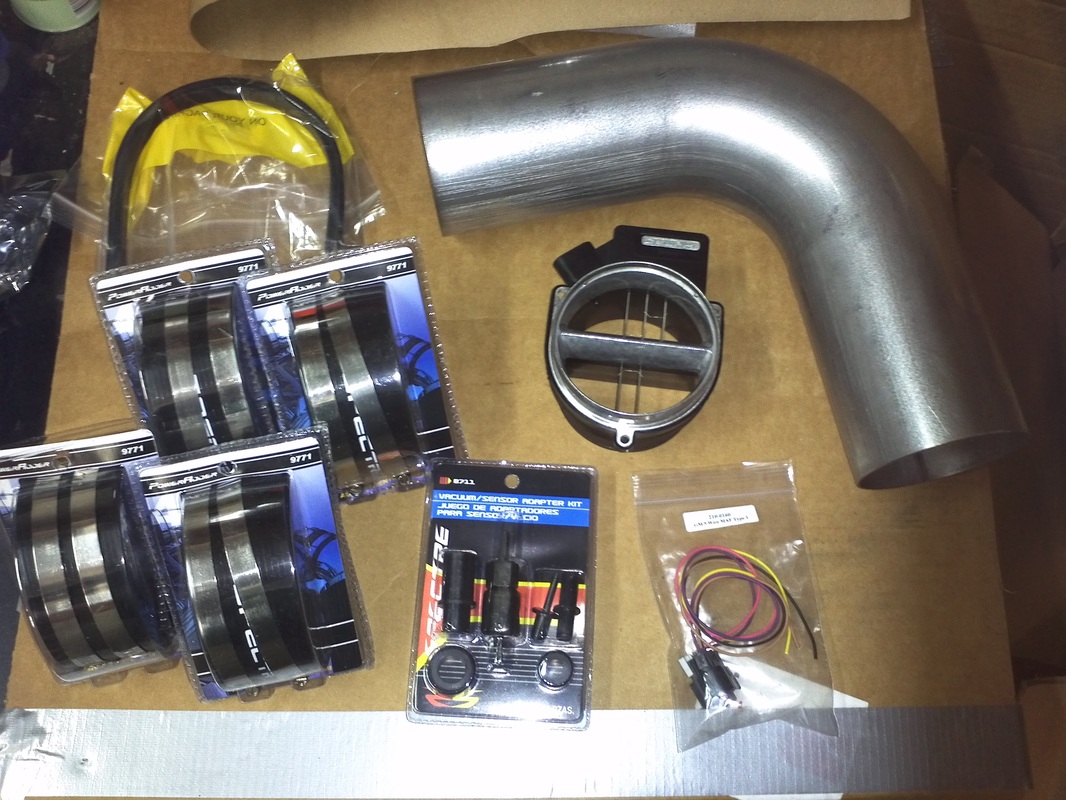
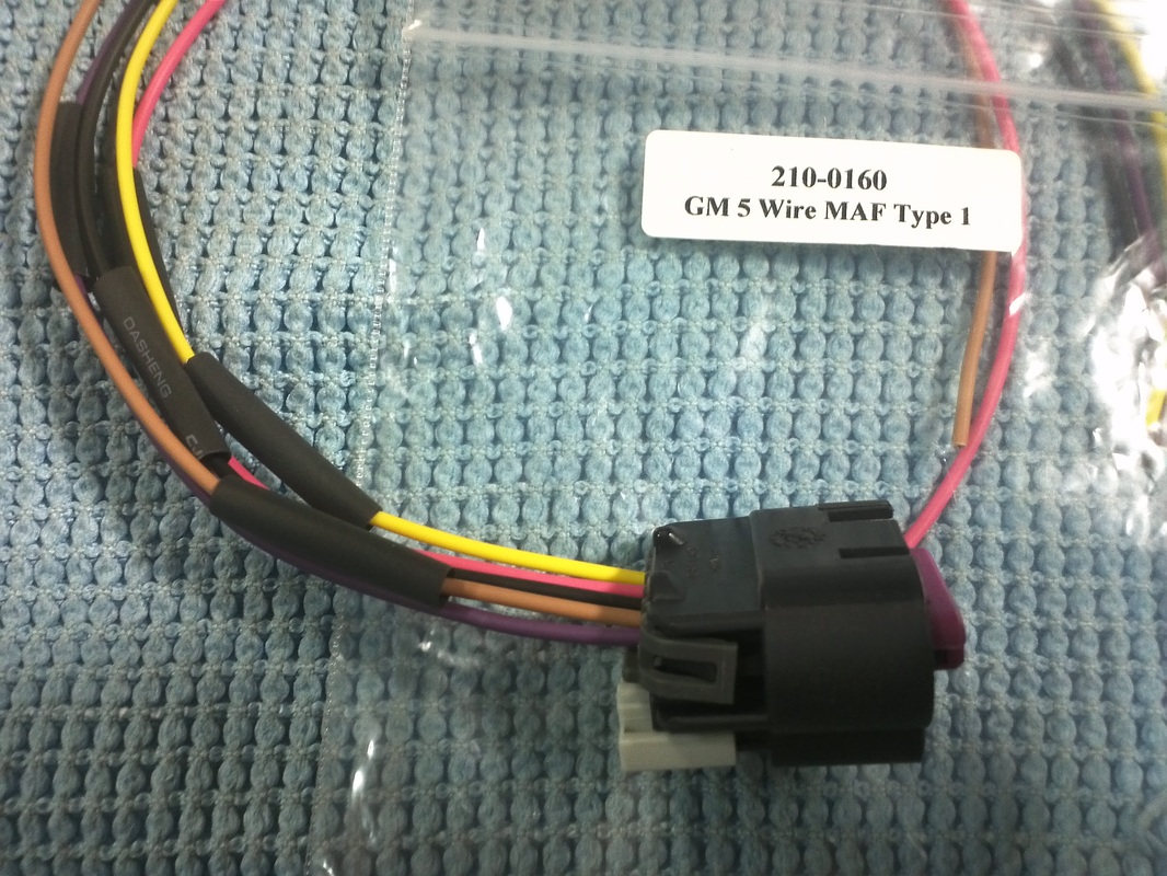
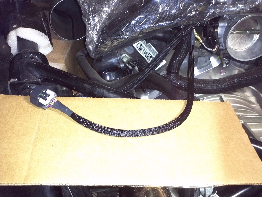
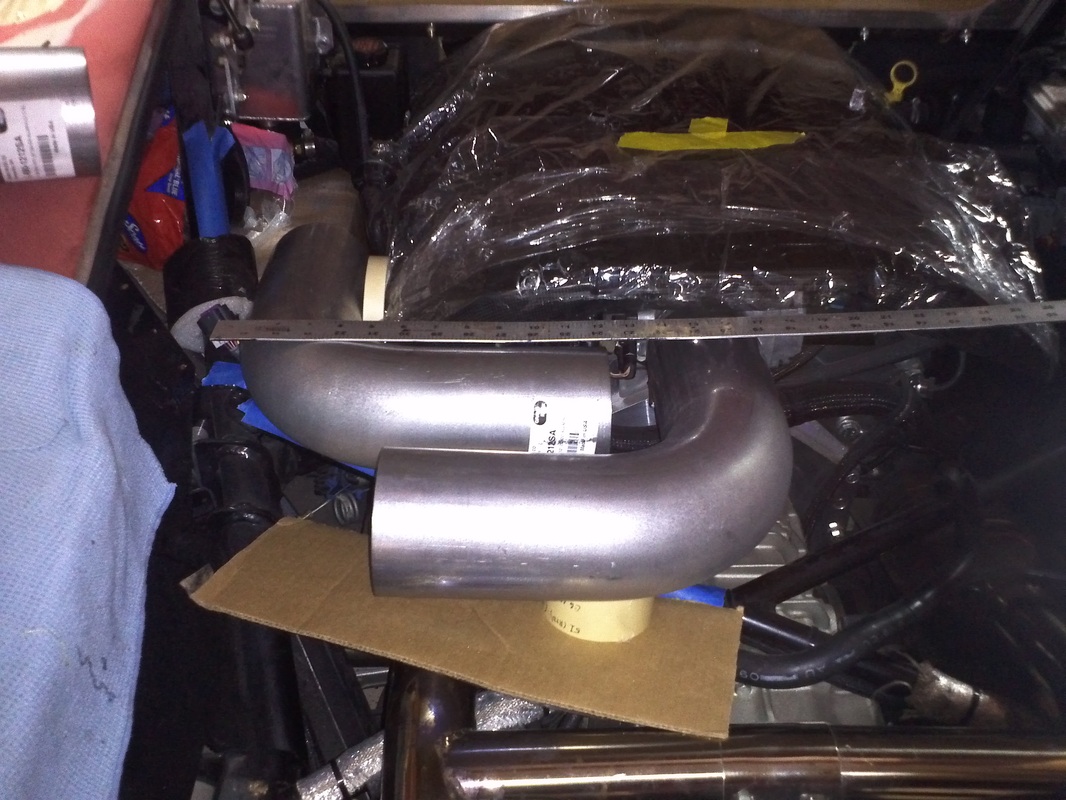
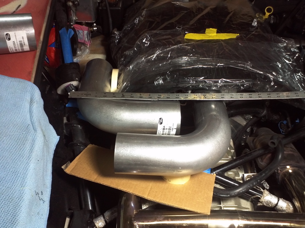
I purchased three 4" 90 degree sections of pipe, four 4" Spectre Couplers, a sensor kit and a GM 5 Wire MAF sensor pigtail. I also purchased a low mileage 85mm MAF from Corvette Recycling to make the factory intended match.
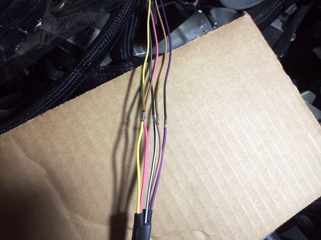
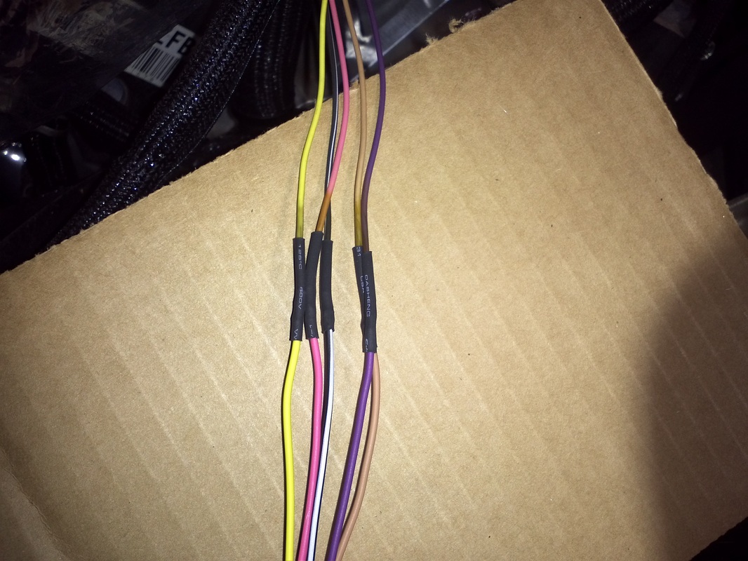
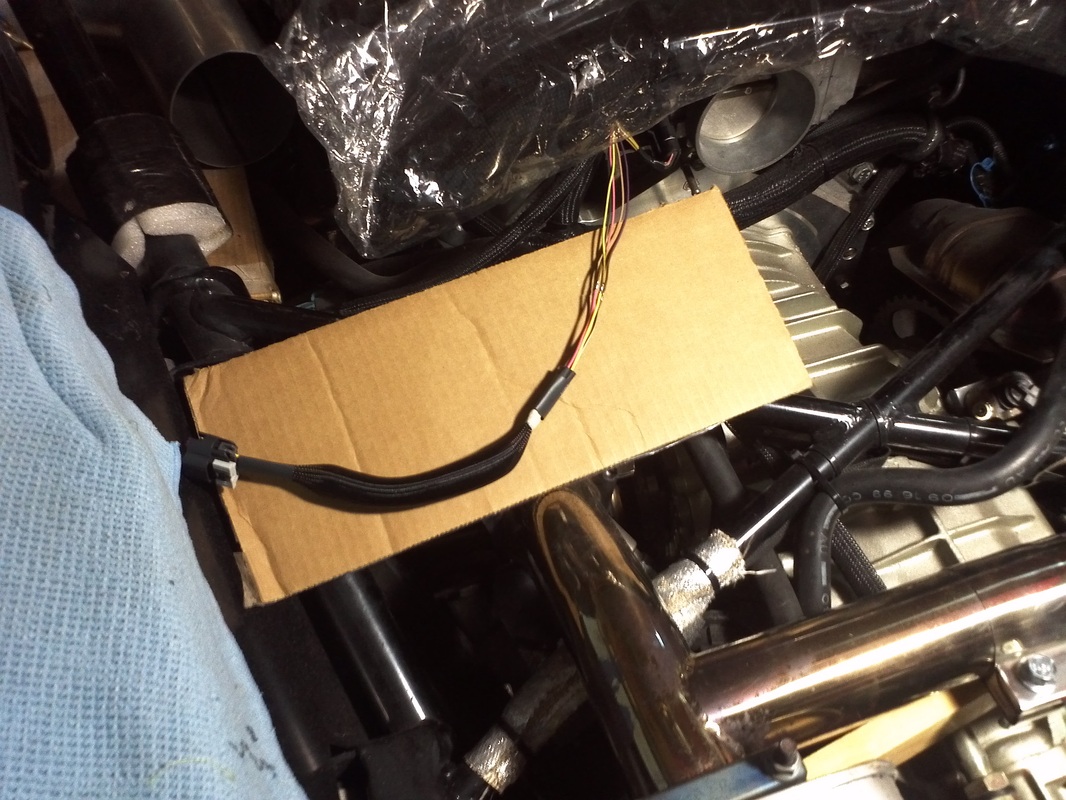
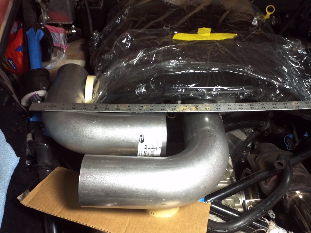
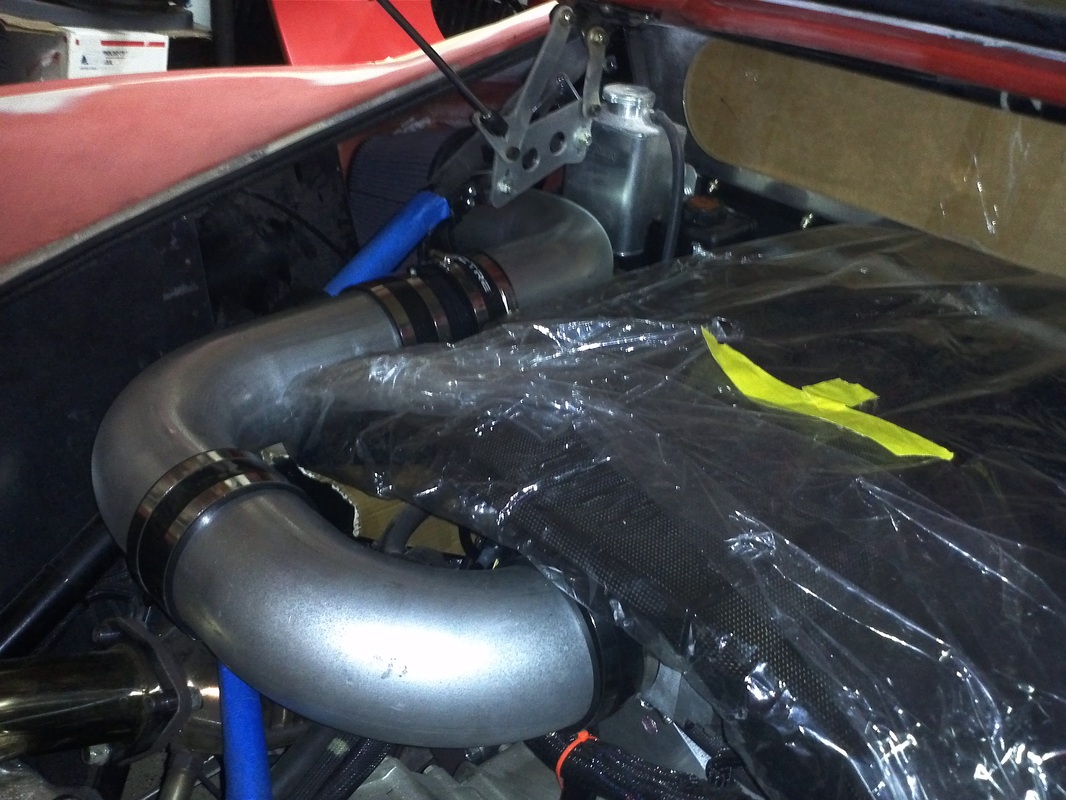
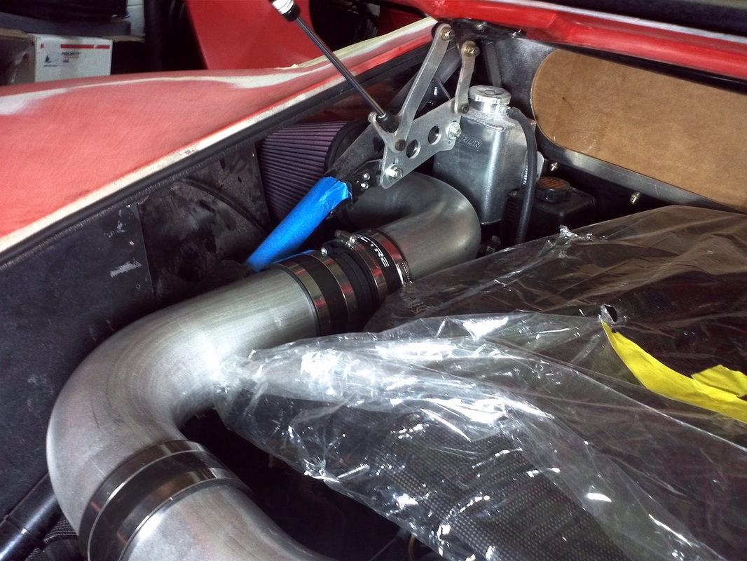
I removed the dual CAI, MAF and IAT sensor. I prepped the GM 5 wire harness with heat shrink and black mesh. I them soldered and covered the connections with the heat shrink tubing. With the harness complete I moved to the 4" tubing. After some placement and measuring I proceeded to make the cuts required. I cut the tube that is connected directly to the throttle body at the angle required to get the intake tubing to clear the X member. I also used the kit supplied filter which has a 4" opening. The filter sets just inside of the intake. this will be the optimum location for a fresh air with out being in a direct line of possible debris and water. I will be using the sensor kit to add a fitting for the emissions air pump connection.
With the 4" CAI installed I started the GTM. I let it idle for about 15 minutes. No DTCs now. With it idling the IAT was 111 degrees. I will experiment with a heat shield try and keep some of the direct engine heat away from the filter area to see if I can lower the IAT.
The pipe is not polished so it will get a coating. I'll plan for powder coat or paint.
With my current dual filter set up the MAF sensor is ~3" from the throttle body. My donor's MAF is the smaller (74.5mm) which doesn't match my 2003 LS6. The 85mm MAF was used in the C5 Z06. This is also the reason I am getting intermitant misfires (DTC P0300) and fuel trim system lean bank 1 and 2 (DTC's P0171 and P0174). These trouble codes can be remedied with a tune also.
I purchased three 4" 90 degree sections of pipe, four 4" Spectre Couplers, a sensor kit and a GM 5 Wire MAF sensor pigtail. I also purchased a low mileage 85mm MAF from Corvette Recycling to make the factory intended match.
I removed the dual CAI, MAF and IAT sensor. I prepped the GM 5 wire harness with heat shrink and black mesh. I them soldered and covered the connections with the heat shrink tubing. With the harness complete I moved to the 4" tubing. After some placement and measuring I proceeded to make the cuts required. I cut the tube that is connected directly to the throttle body at the angle required to get the intake tubing to clear the X member. I also used the kit supplied filter which has a 4" opening. The filter sets just inside of the intake. this will be the optimum location for a fresh air with out being in a direct line of possible debris and water. I will be using the sensor kit to add a fitting for the emissions air pump connection.
With the 4" CAI installed I started the GTM. I let it idle for about 15 minutes. No DTCs now. With it idling the IAT was 111 degrees. I will experiment with a heat shield try and keep some of the direct engine heat away from the filter area to see if I can lower the IAT.
The pipe is not polished so it will get a coating. I'll plan for powder coat or paint.


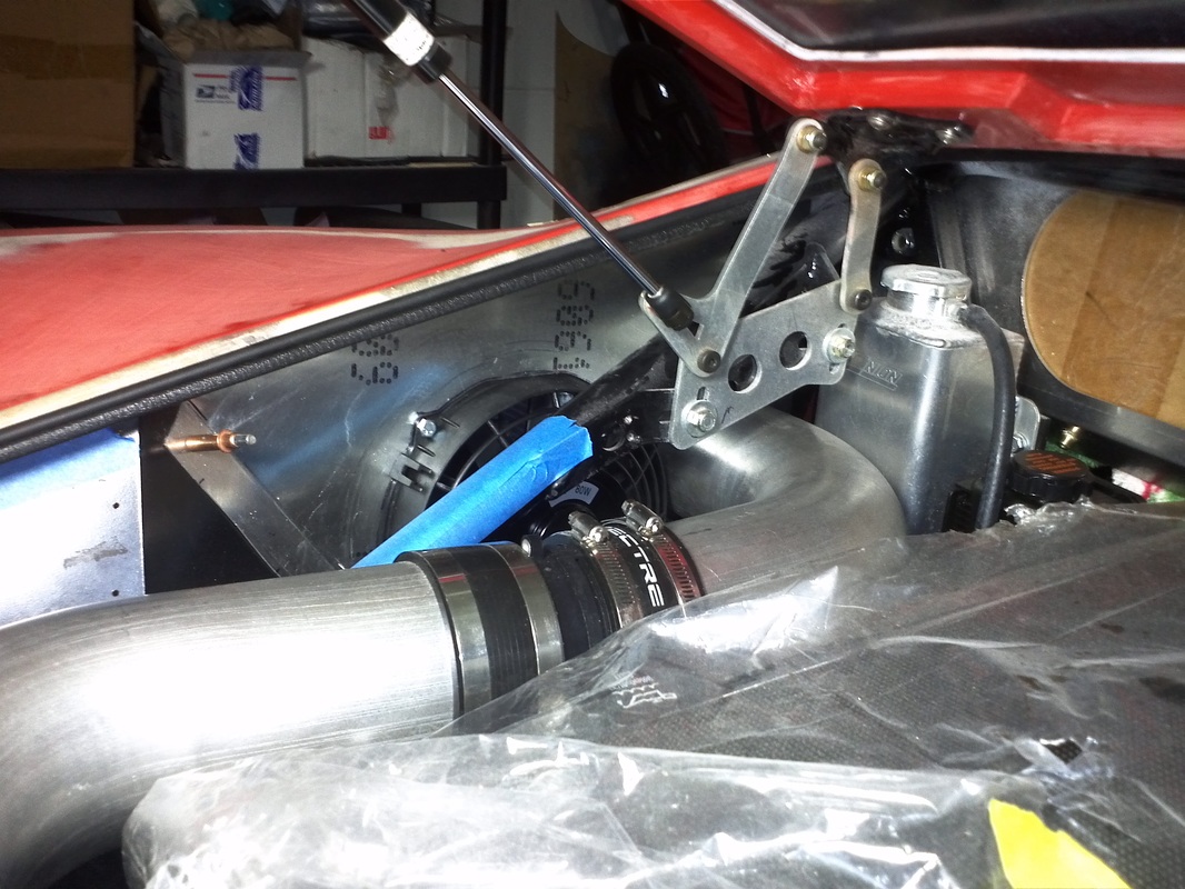
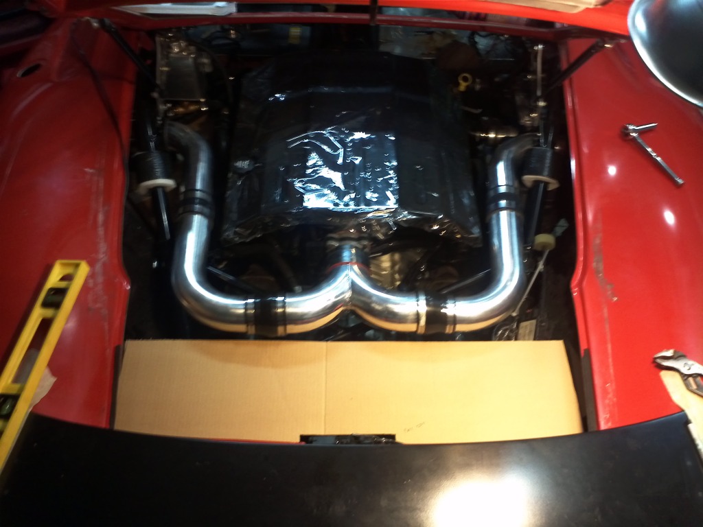
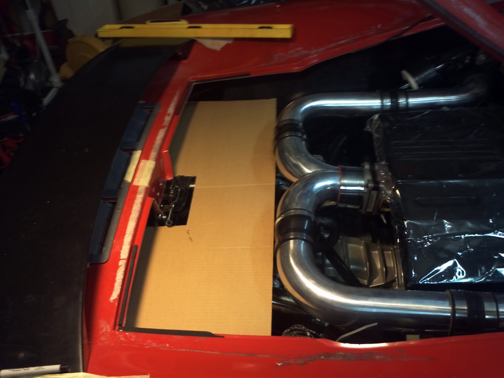
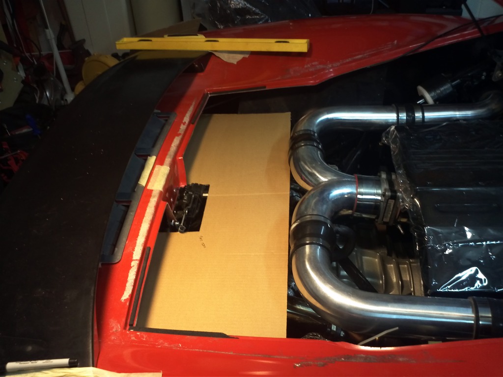
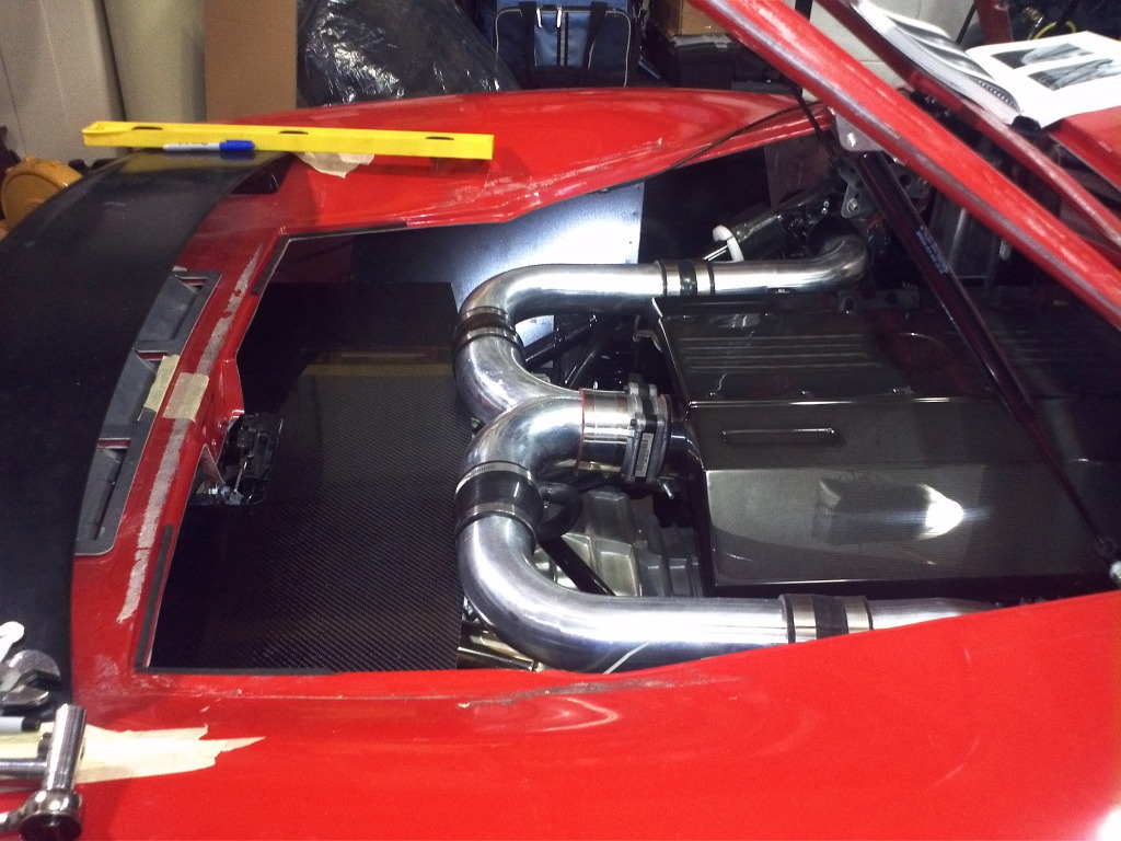
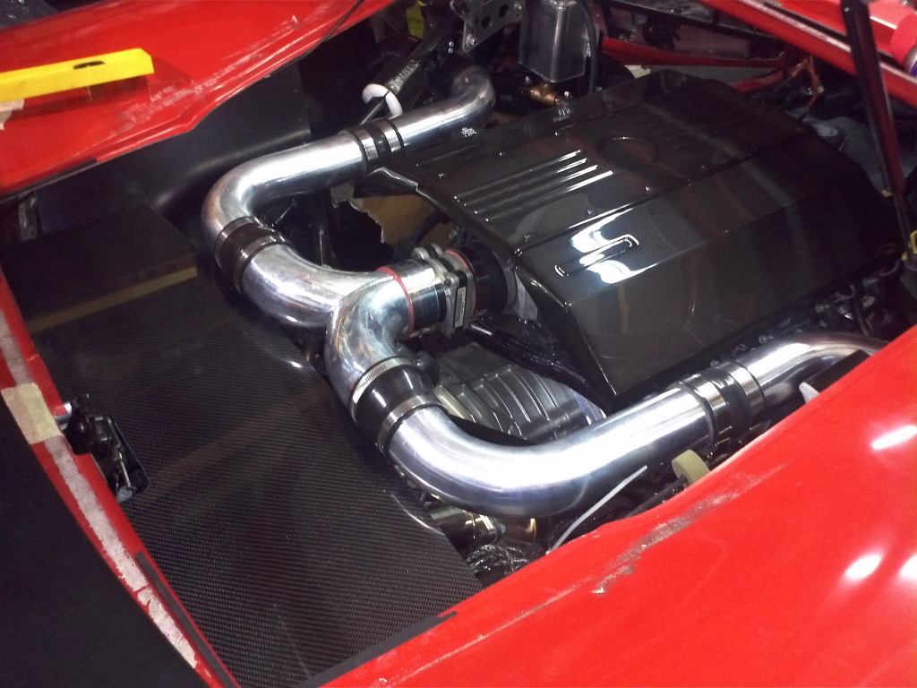
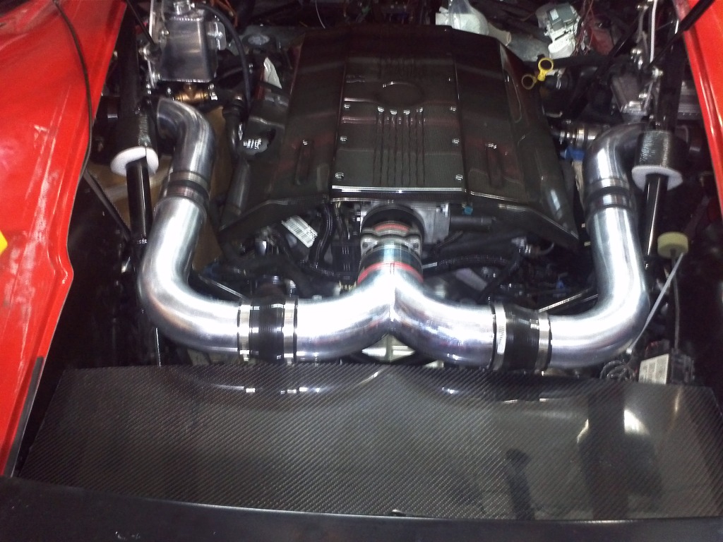
Carbon Fiber Engine Cover and Carbon Fiber Engine Bay Detail Panel and CAI Plumbed into Side Scoop
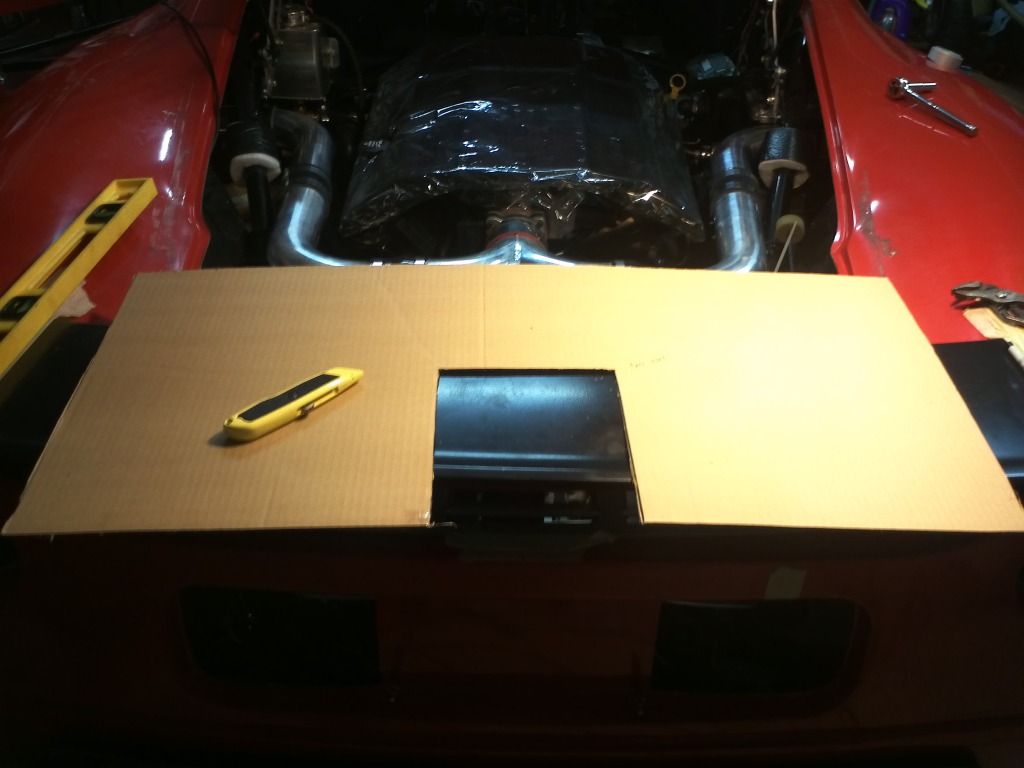
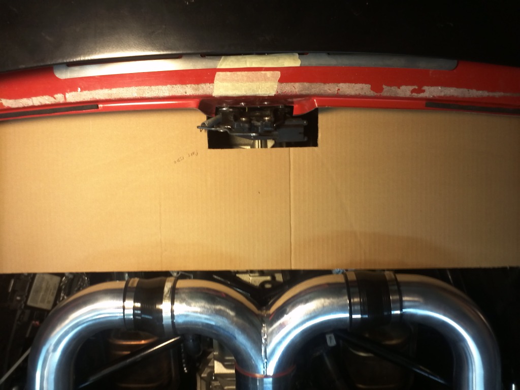
I plumbed the CAI into the side scoop area. Then I pulled the engine cover out and placed it on the engine. I then moved to making a cardboard template for the cf piece I will use to dress the engine bay aft of the CAI. I then transferred the pattern to the cf, taped around the cuts and used my jigsaw with a metal cutting blade (for a clean cut). I will be wrapping the mufflers, placing standoffs and adding some heat reflective material to the back of the cf panel. This simple piece alone with the engine cover really cleans up the engine bay.
I ordered two 75 degree elbows that I will use in the area over the fuel tank covers to better match the angle of the close out panel in that area.
I ordered two 75 degree elbows that I will use in the area over the fuel tank covers to better match the angle of the close out panel in that area.


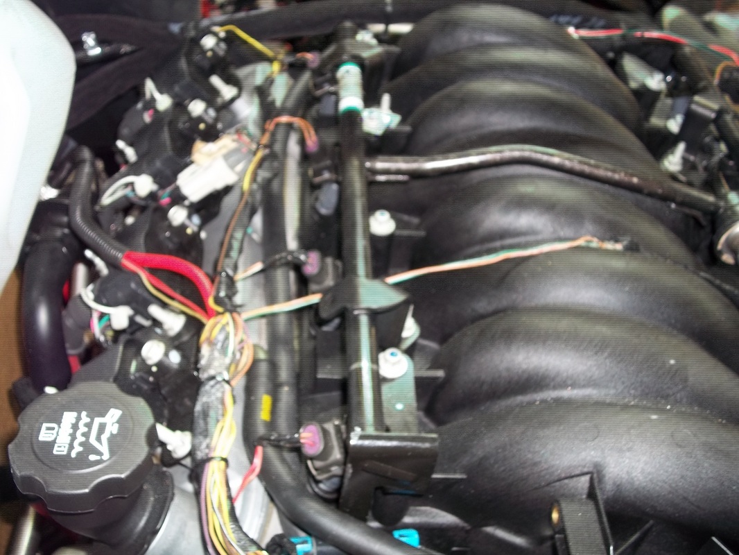
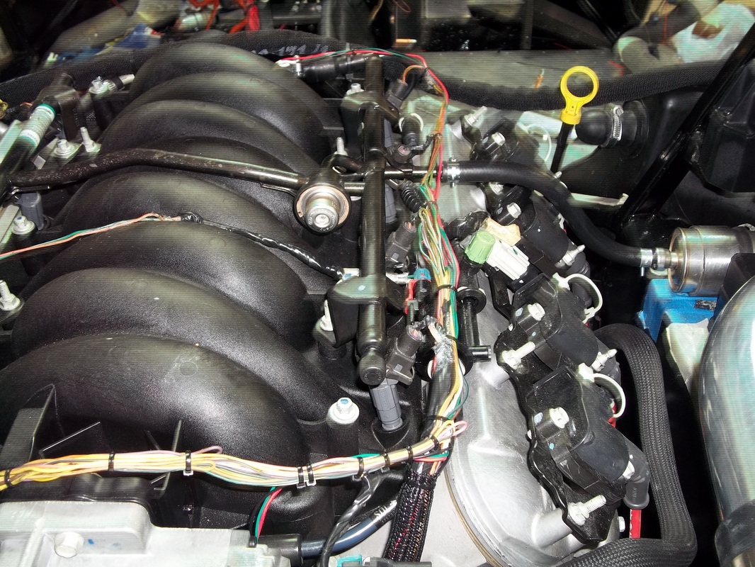
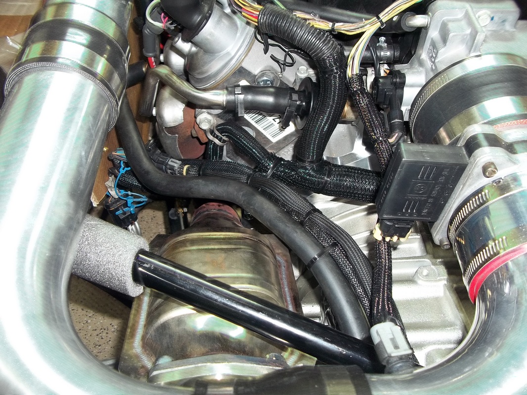
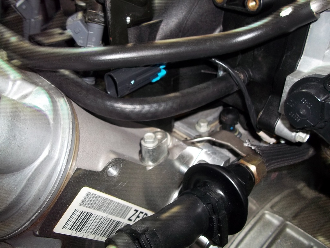
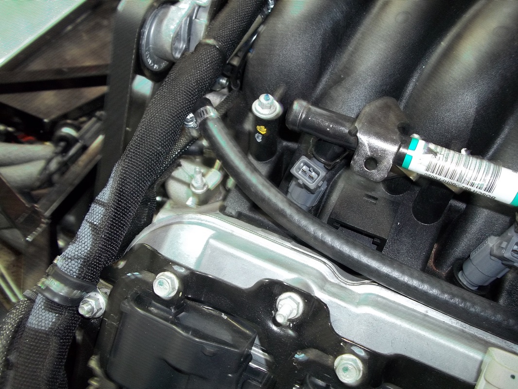
Engine Bay wire detailing.
These are the same photos from the electrical page. Detailing and securing for a high-end OEM look.

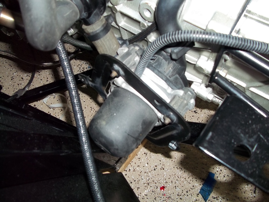
First Start
I attempted to start it Sunday evening with no luck. The fuel pump was not coming on. It would fire but not run. With advice from LSMan from the ffcars fourm and Luck131969 from the corvette forum I discovered that I did not ground SP122 to G105. It was a ground wire on the engine harness near the oil filter. After grounding it and securing a few items that I did not want touching the Cat Pipes. I proceeded to start the LS6. It fired right up with a rough idle. So I pumped the throttle pedal just enough to keep it running while the PCM learned idle. after a few minutes the LS6 was purring beautifully.
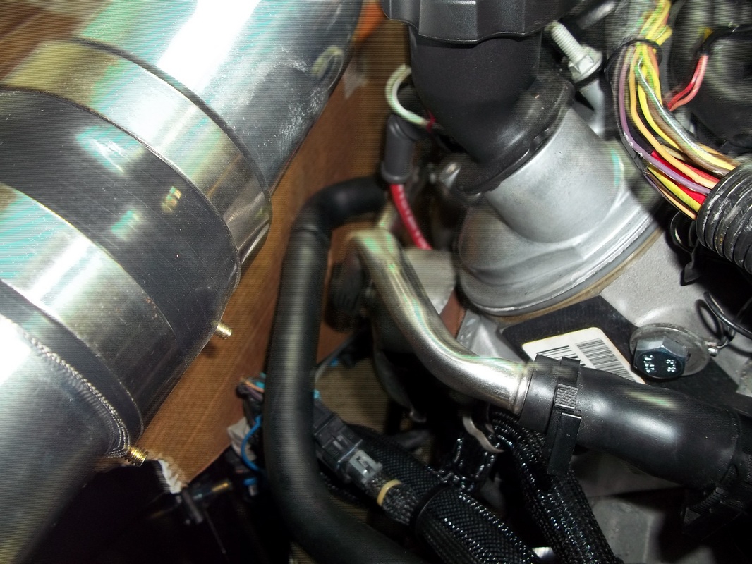
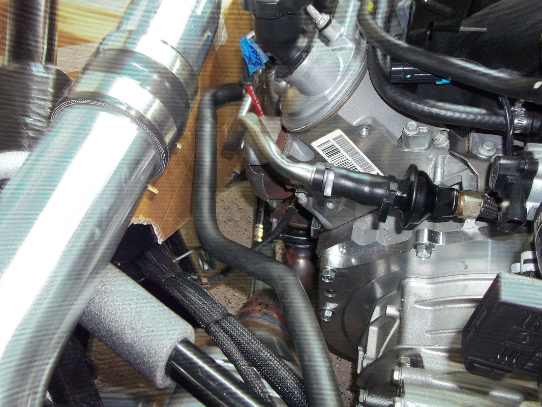
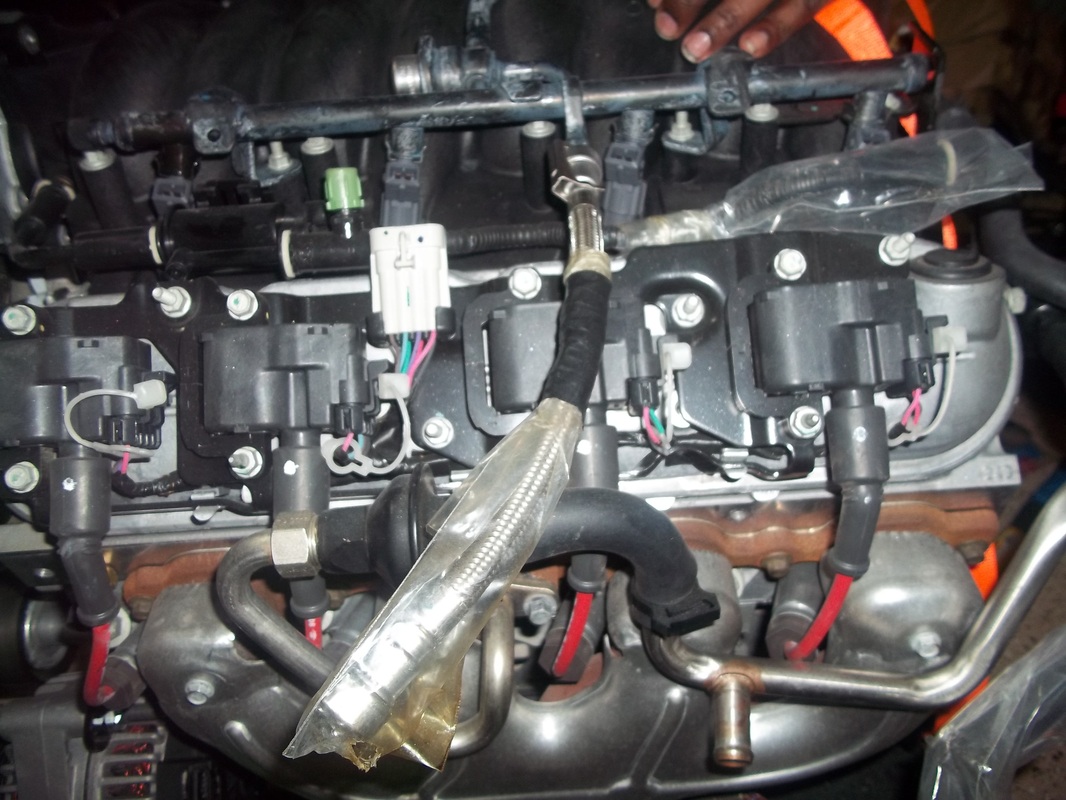
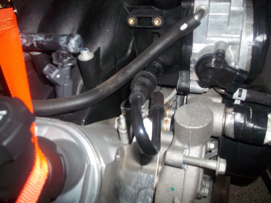
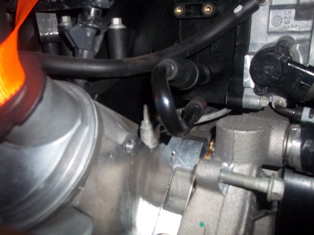
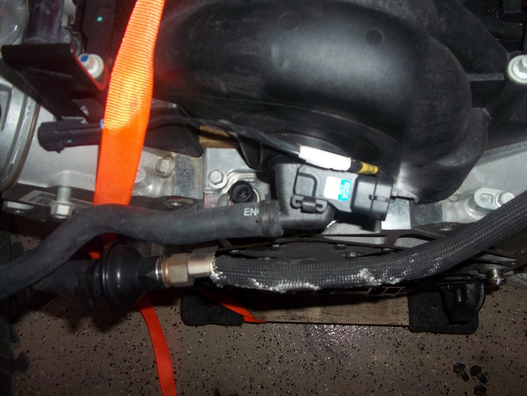
Engine Management/Emissions Systems
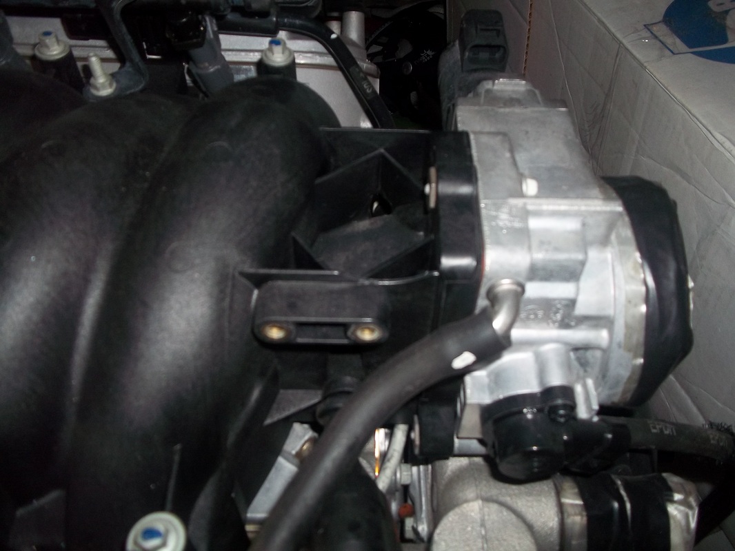
Since I am transplanting almost all of the corvette systems I have to rework any plumbing that is misplaced after installation into the GTM. I used donor hard fuel lines and fuel injection hose to complete the connection of the purge line and manifold to throttle body.
CAI
I believe David Borden did this prior to FFR. It looks Identical and is an easy DYI at half the cost.

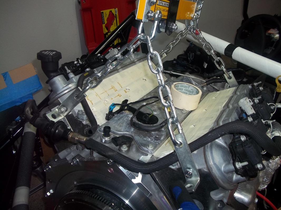
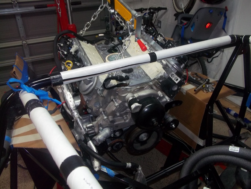
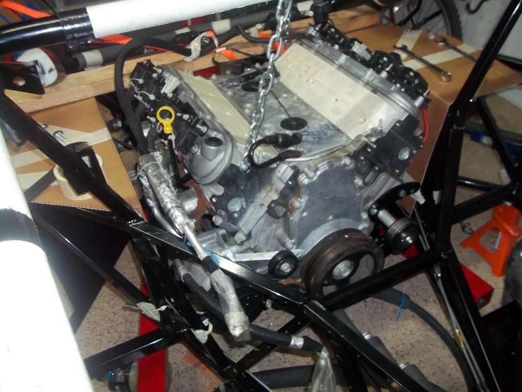
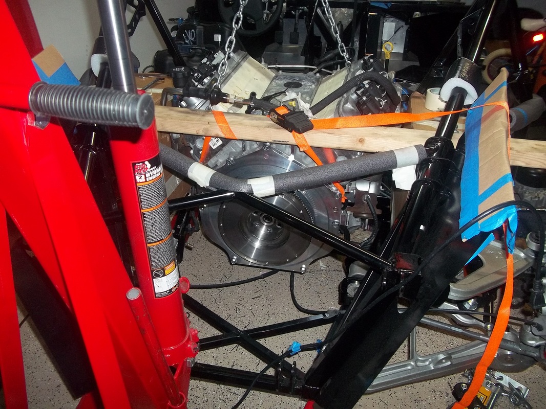
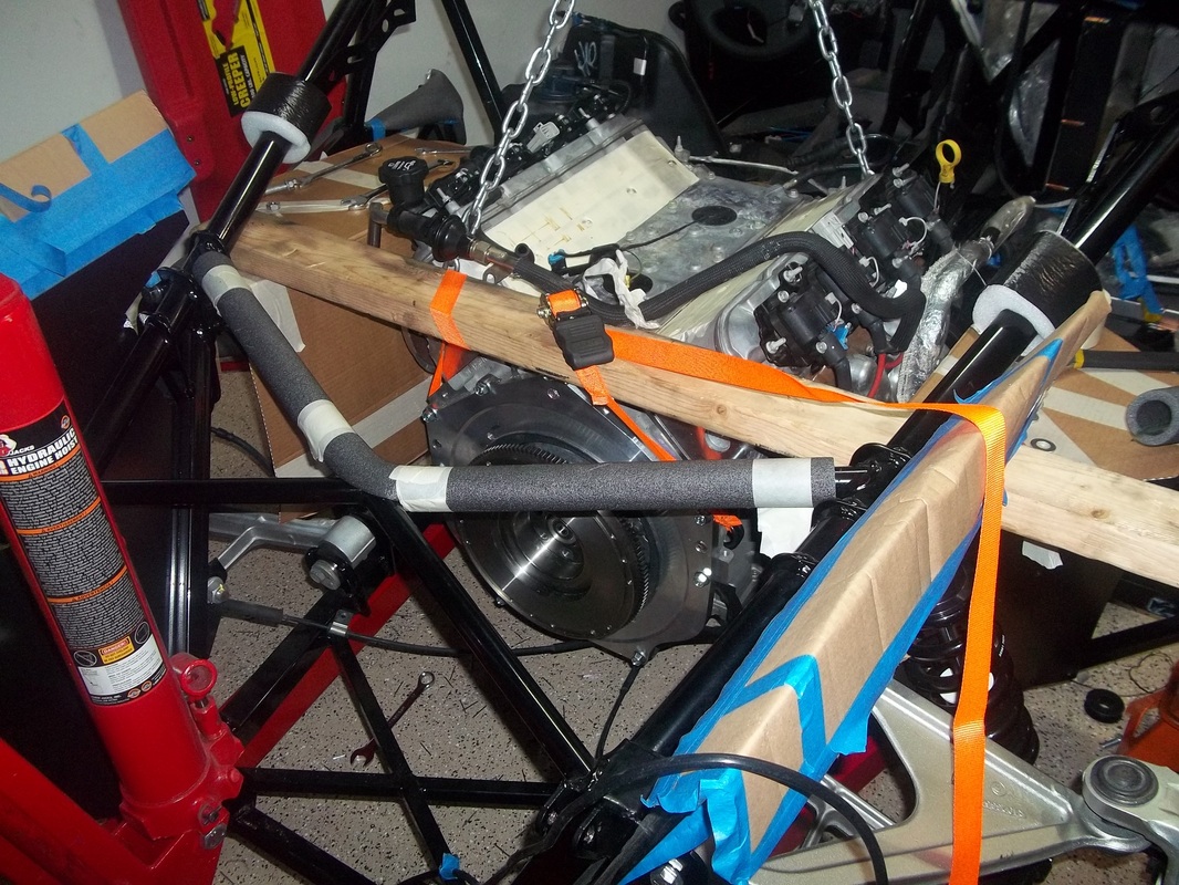
LS6 Preparation and Install.
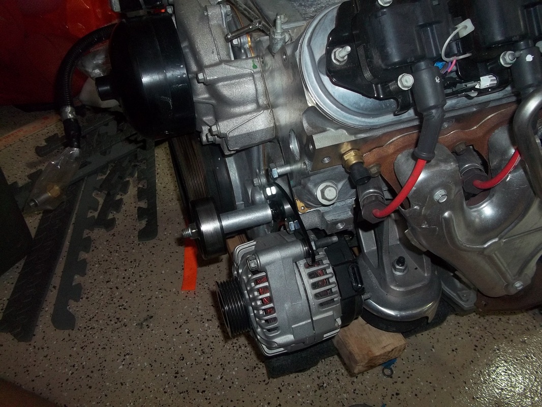
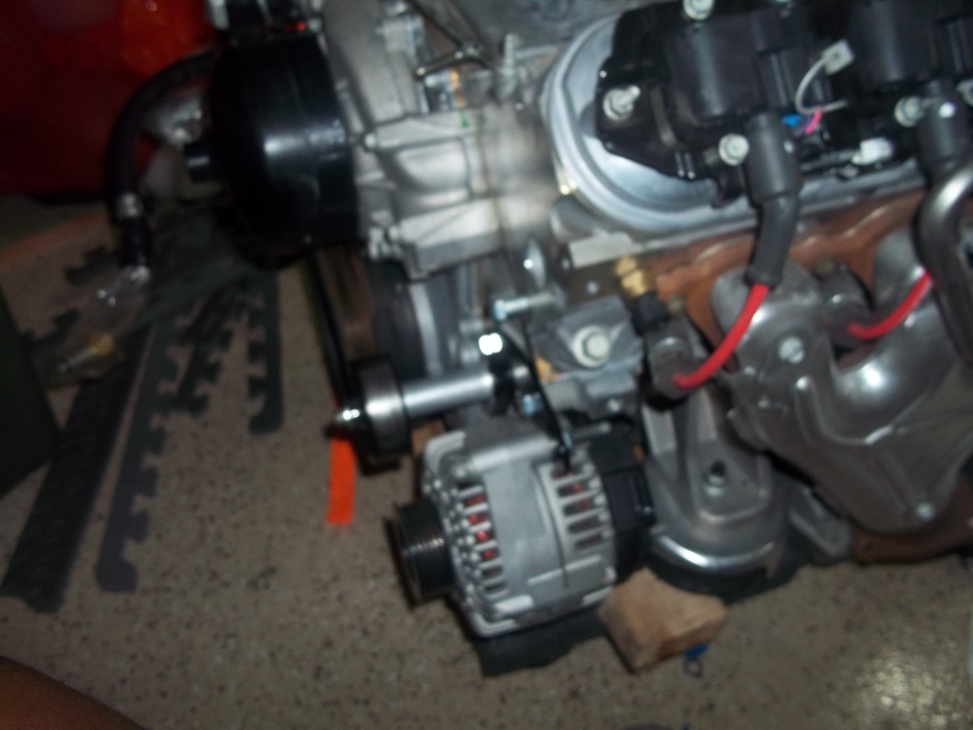
I was able to get the engine in by myself. Took about an hour. I had to remove the relocated alternator and after 20 minutes of trying to get the engine mount studs to line up I removed the water pump. I used the leveler to get the engine past the upper bar. After it was clear and straight I used some 2x4s to hold the engine while I removed the leveler for the trusty chain.


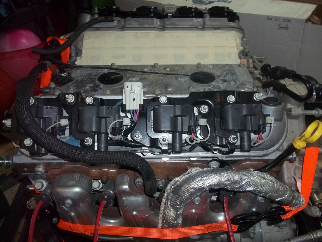

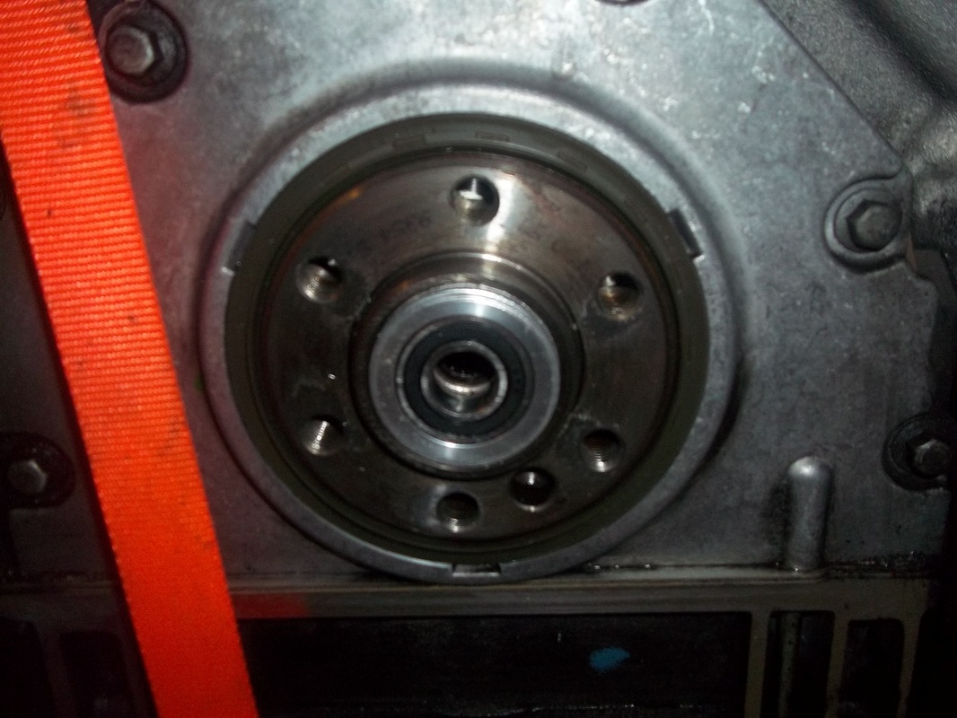
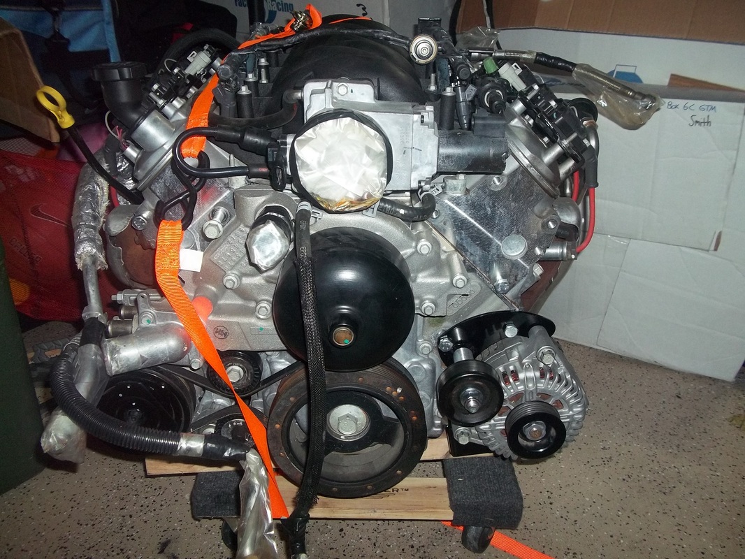


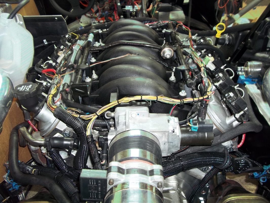
LS6
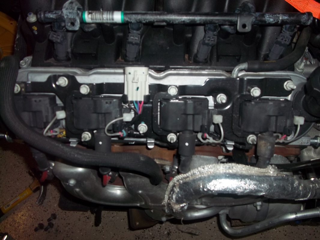
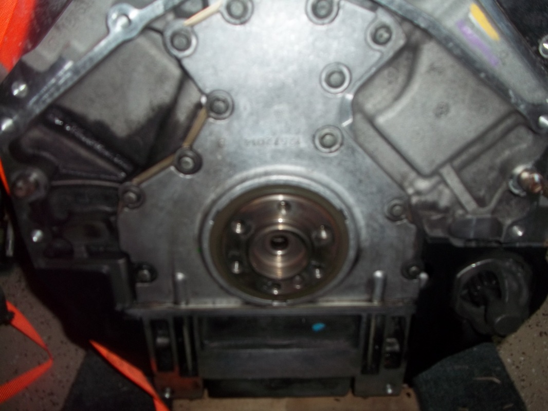
LS6 with less than 16000 miles and all accessories.
I purchased the LS6 from Corvette Recycling. It came complete with all of the belt-driven accessories and PCM. The harness was sold form the engine the same morning I called to purchase it, but Colton dropped the price $500 for that reason. I also knew I would get a harness with my donor so I was not concerned that it was not included. The engine looks new and the stock clutch assembly is still attached.
FFR includes a shipping box for the PCM to be shipped to them for flashing. I asked Jason what was done to the PCM by them. He replied that the VATS is disabled. I do not know if FFR flashes a manual transmission program if your PCM is from an automatic.

