AC Evacuation and Charge following Drier Relocation for Magnasteer Power Steering Install
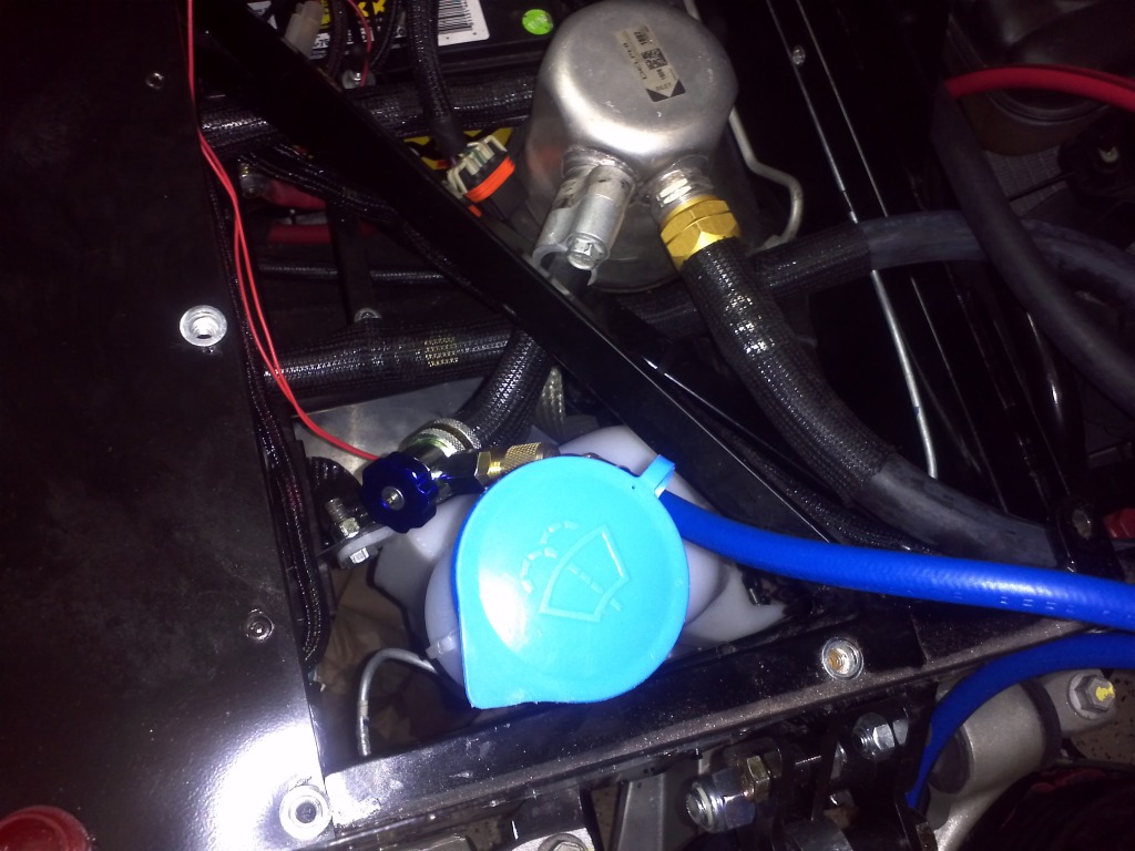
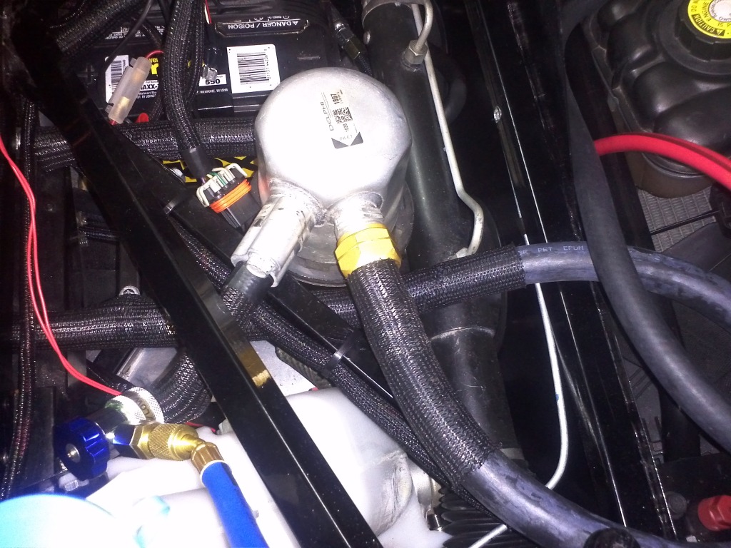
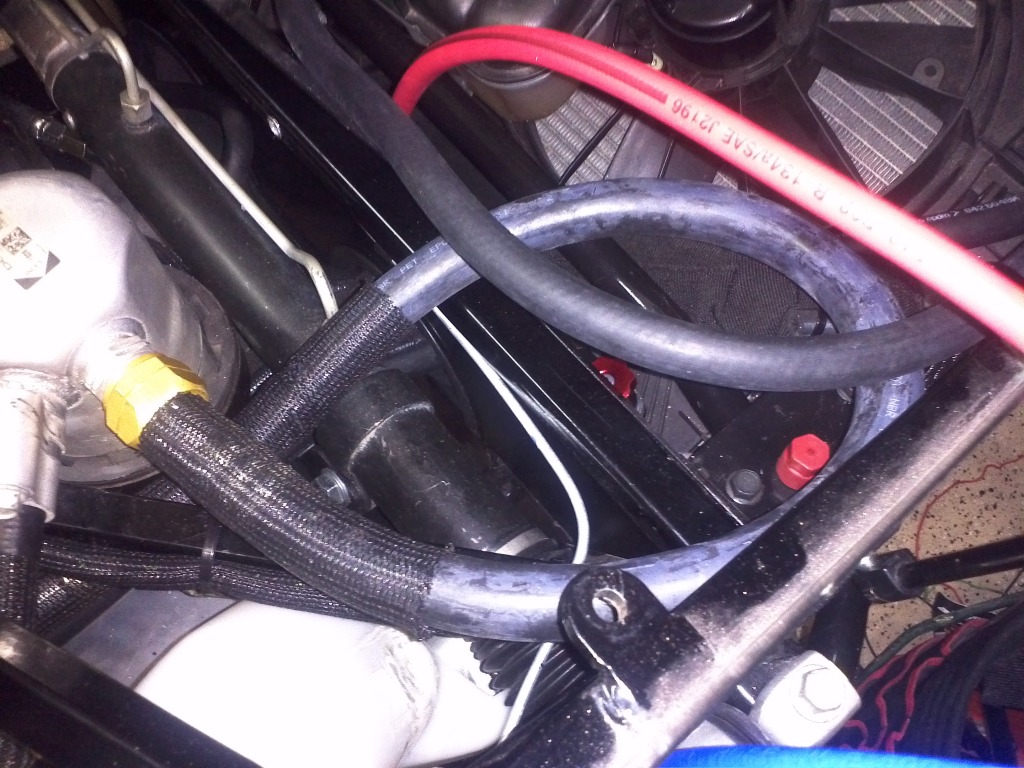
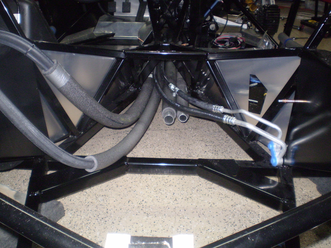
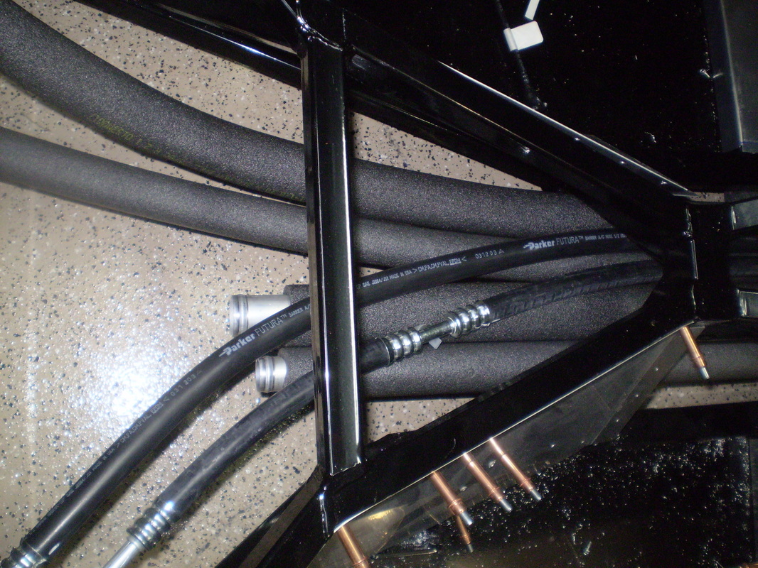
I had to relocate the drier from the position over the manual rack. To do this the hose from the evaporator needed to be reworked. To keep from having to have a custom hardline made I opted for a 30" custom flexible hose that allowed me to made the connections with a gentle loop.
AC
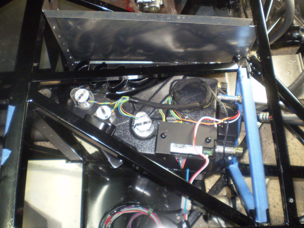
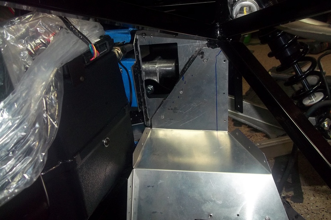
I finally have moved to completing the Passenger foot box. The evaporator is installed during this part of the build. I followed the instructions for getting the evaporator in place and had no issues. It was easily placed into the forward tunnel. After getting it in place I could only see the two passenger side screws where the fan attaches. I moved the front of the evaporator toward the passenger side of the car to expose the upper driver's side screw. You need these three screws for the fan relocation plenum. After getting the evaporator in the position I need and test fitting the inner part of the plenum I installed the two rivnuts and bolted the evaporator to the chassis. I then drilled a new hole in the rear bracke and attached it to the evaporator and then rivited it to the chassis.
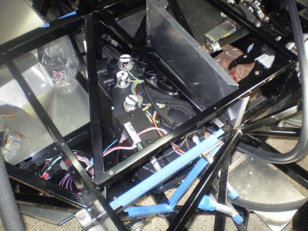
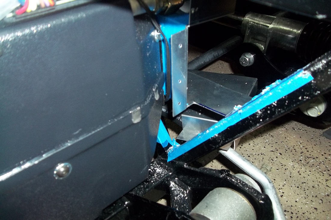
Now to the plenum. I placed tape on the back, set it inplace and tapped on it in the three corners where the holes will be drilled. This left an indent in the tape giving me the marks for drilling the holes. I then fitted and drilled and cleco'd the passenger foot box panels to test the fit of every thing. Then I removed and permently reinstalled the foot box. I have removed the plenum for powder coating on my next run.
Now to the plenum. I placed tape on the back, set it inplace and tapped on it in the three corners where the holes will be drilled. This left an indent in the tape giving me the marks for drilling the holes. I then fitted and drilled and cleco'd the passenger foot box panels to test the fit of every thing. Then I removed and permently reinstalled the foot box. I have removed the plenum for powder coating on my next run.


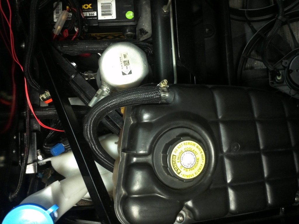
HVAC System Evacuation, Leak Check and Charge.
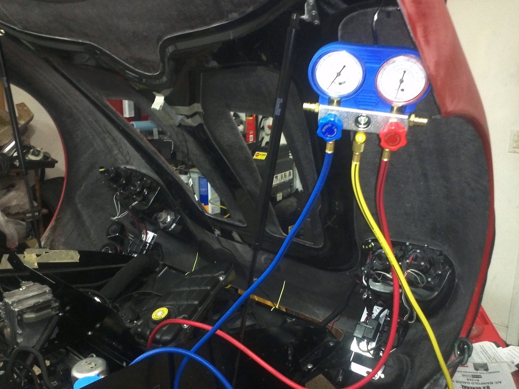
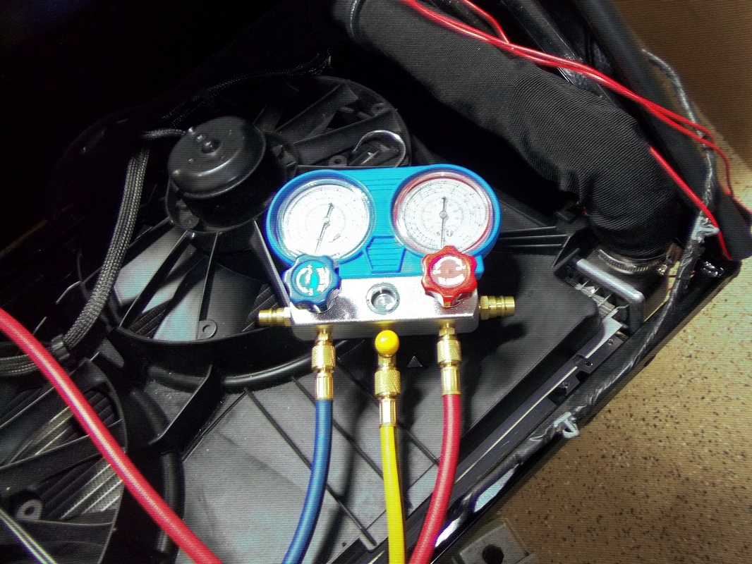
I rented a vacuum pump and connected my manifold gauge to my HVAC System. I quickly discovered a leak at the drier connection. The "O" ring provided with the Vintage Air (VA) kit was much thinner than the stock "O" ring. So I changed it out and checked the system again for leaks. The vacuum was perfect and held for over 5 hours without a change in vacuum. I previously poured the required amount of oil into the system prior to making the final connection. So after evacuating the moister/air from the system I charged the system. The VA instructions state approximately 1.8lbs or 28.8oz and HIGH-SIDE PRESSURES (160-250 PSI), LOW-SIDE PRESSURES (06-12 PSI in a steady state). I used three 12oz cans of R-134 and achieved a high side pressure of 205psi and a low side steady state of 9 psi. The vent temperature was 47 degrees at idle.
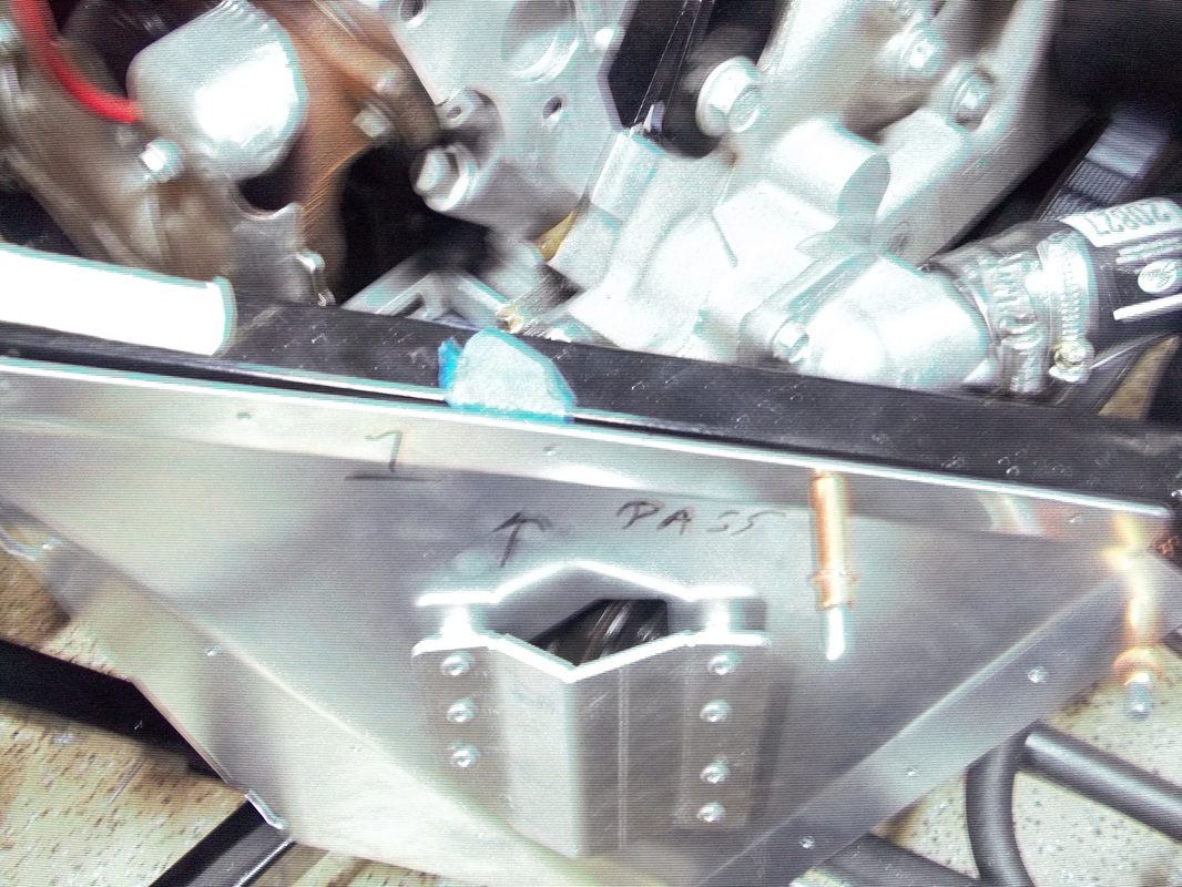
Compressor Cover Plate