|
|
|
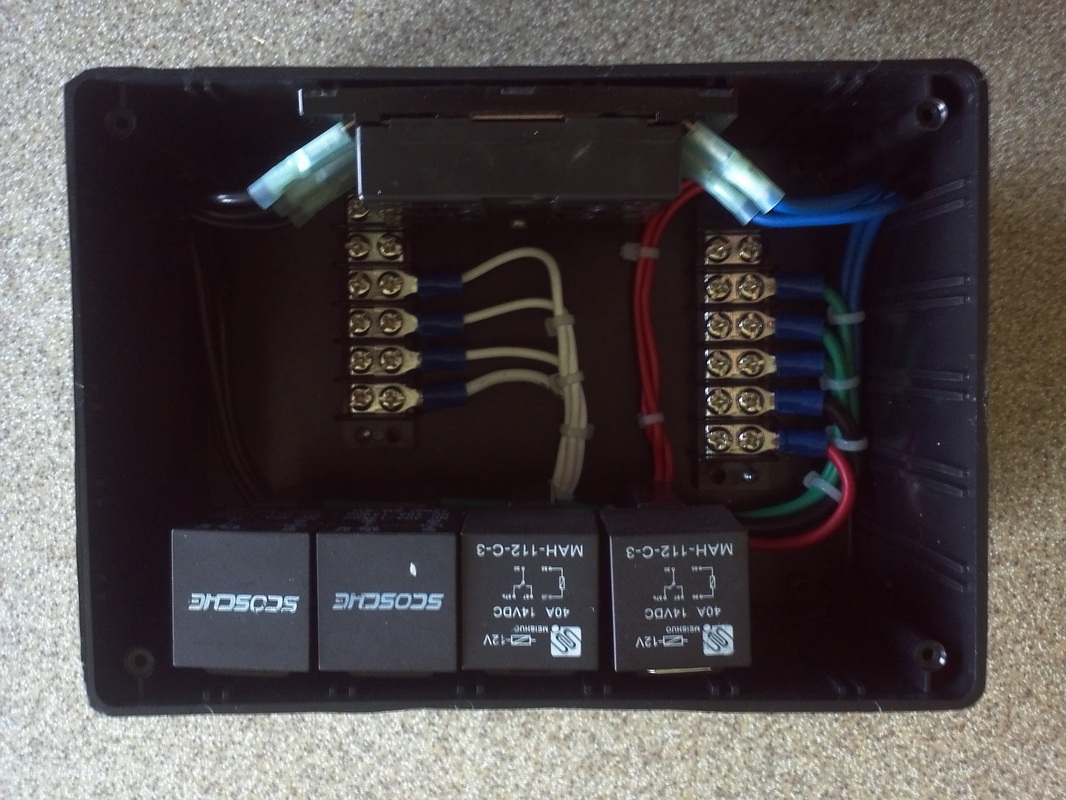
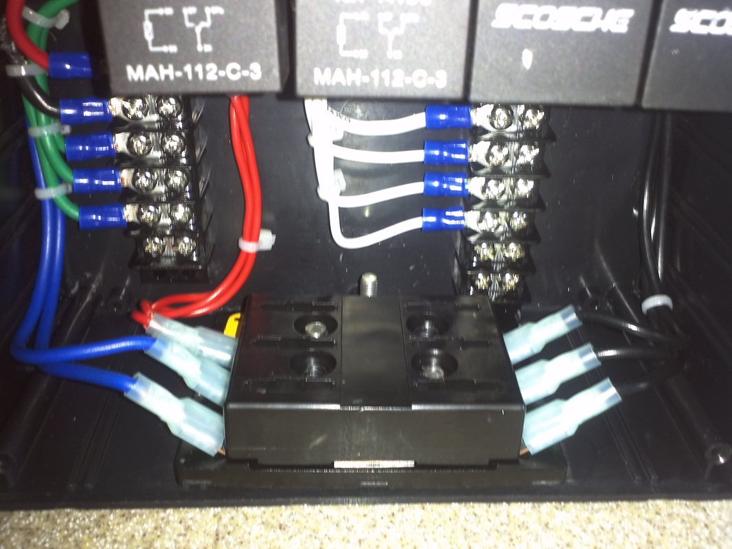
Four Circuit Relay Panel
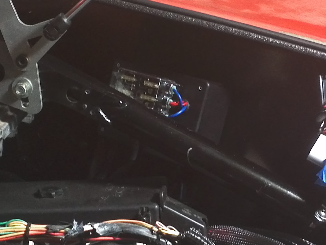
Initially I was going to purchase some weather proof relays to handle the lift compressor, engine bay fans and tunnel fan. Then I discovered the price of the relay and matching harness. So using some of the may automotive 40/30 relays and harnesses, I have on hand, I decided to use them. Because these will be in the engine bay, I still needed some protection for them. So I opted to build a relay panel inside of an abs project box.
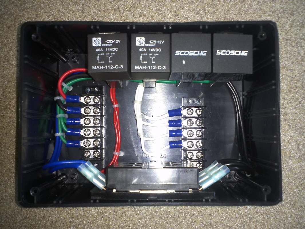
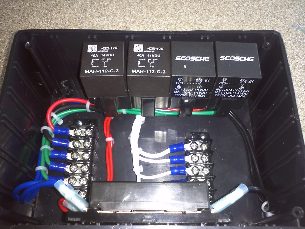
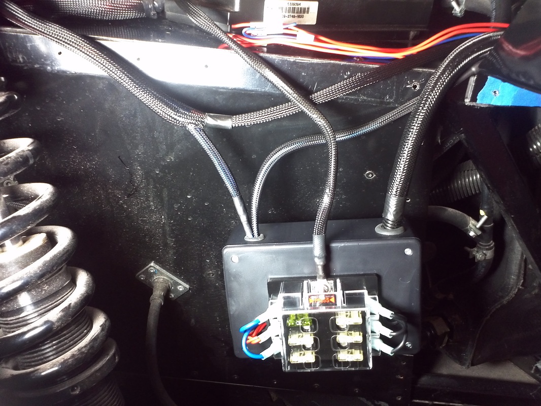
After placing it on the panel I decided i did not like how much space it consumed. So I made another run to the shack for a smaller project box. had to move the fuse panel to the outside.
I also ran a few extra wires for potential future items. Still need to place cover in braided sleeve and secure them.


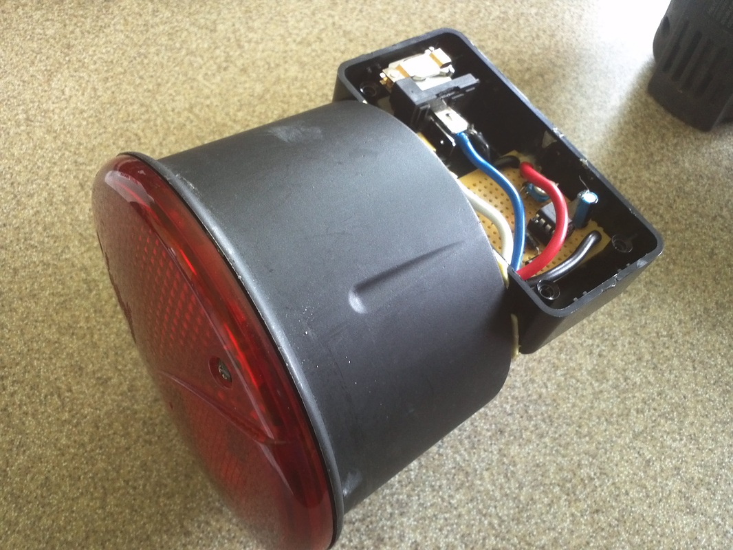
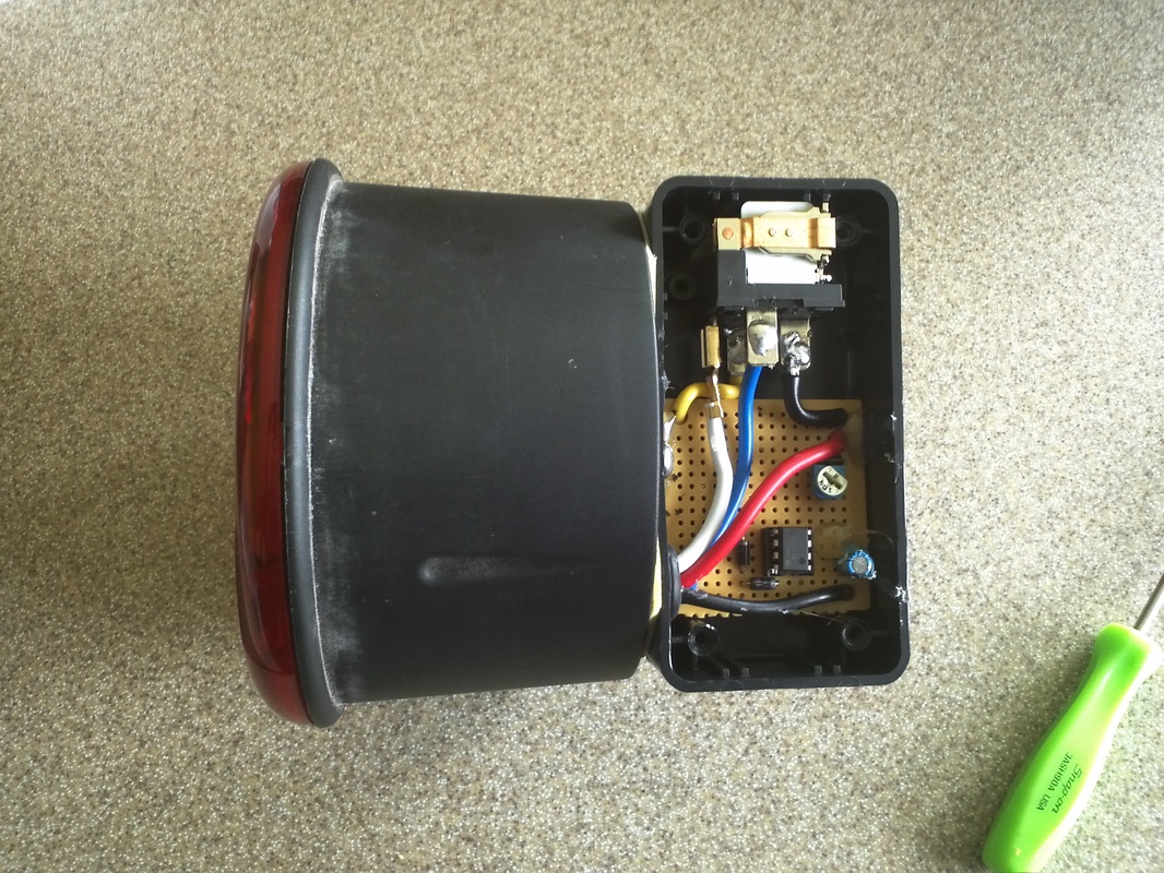
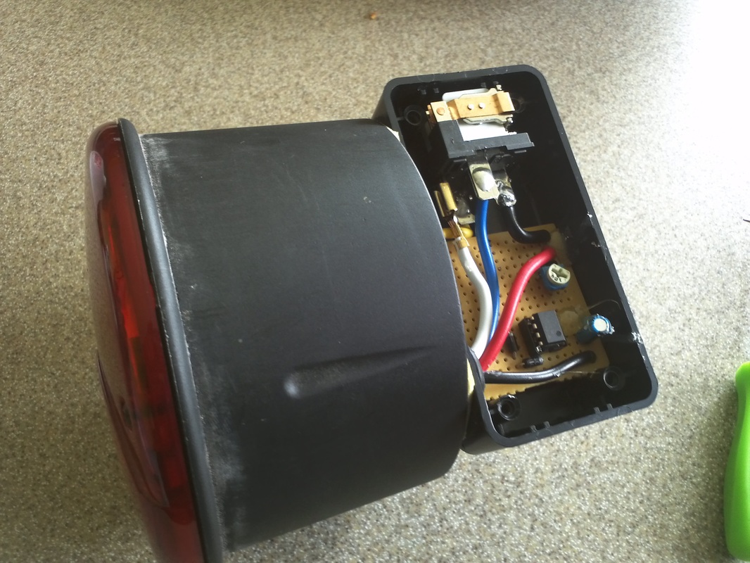
Delay Circuit for Sequential Tail Lights
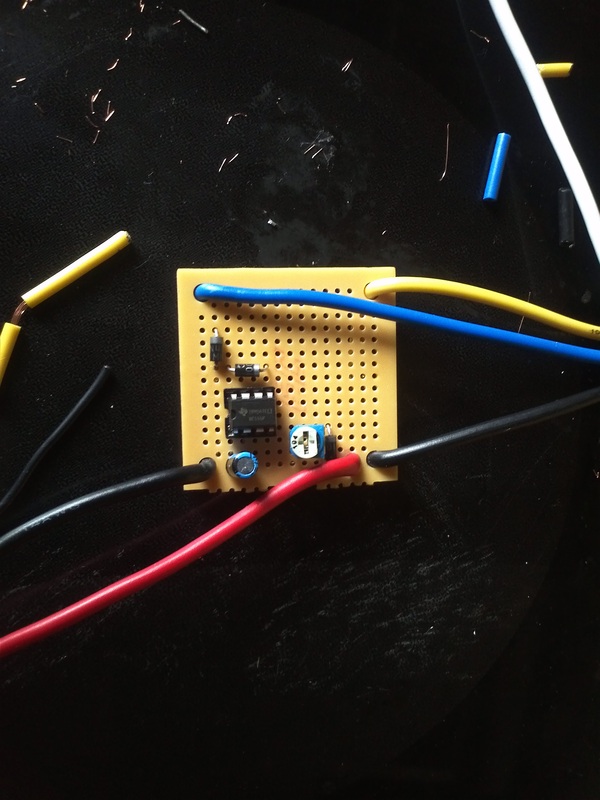
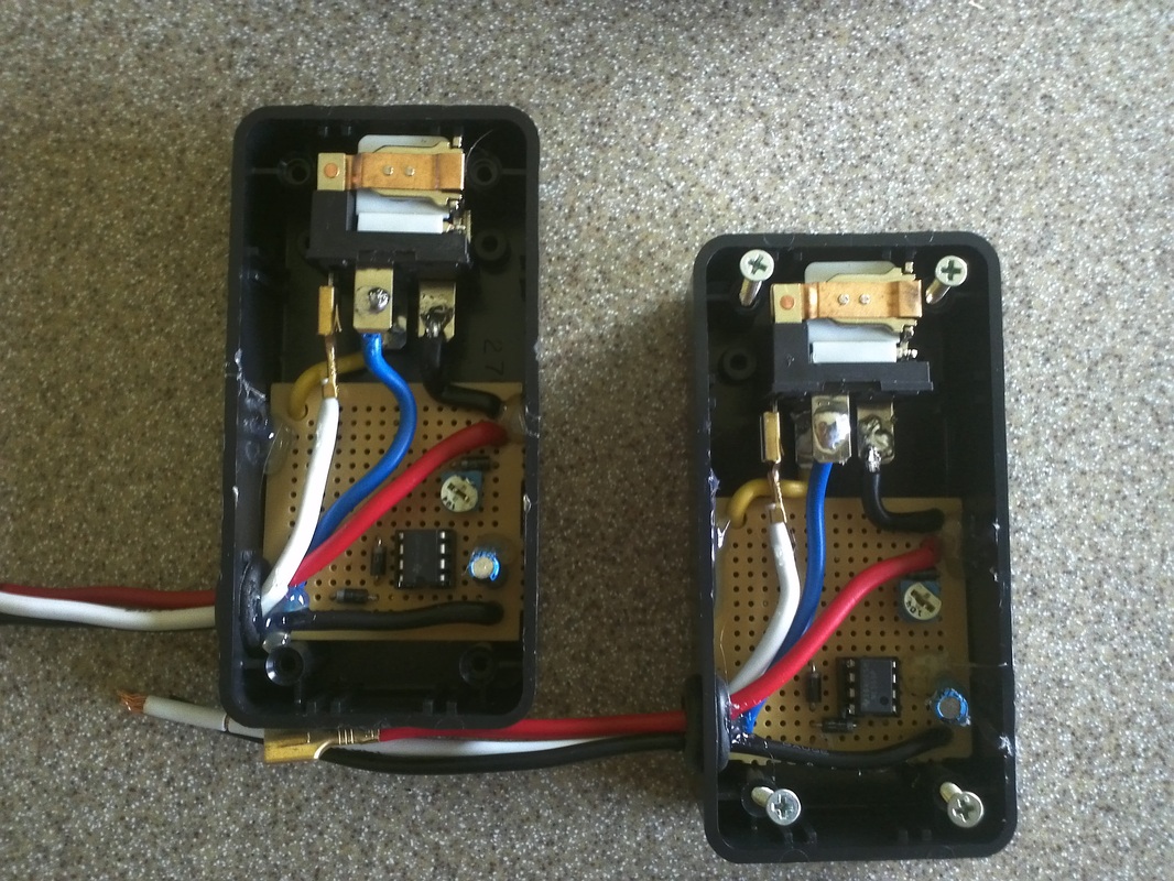
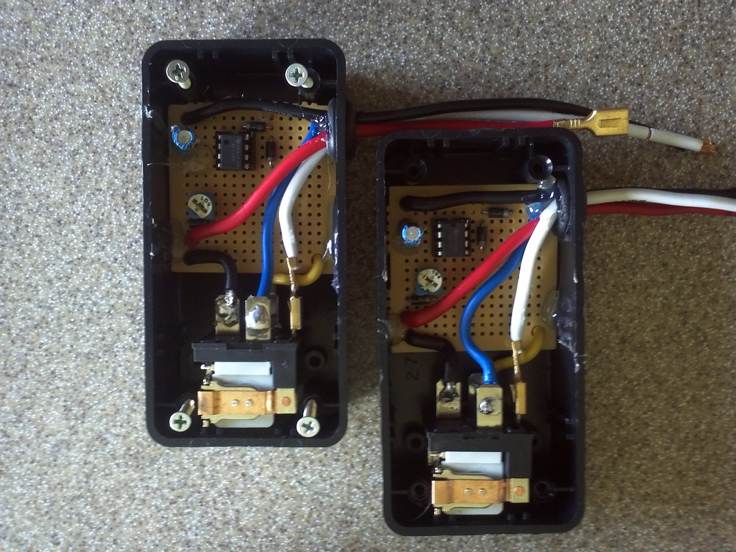
Built a set of delay circuits using a high current 555IC. I placed each of them in a 3x2x1" project box and secured them to the back of the housing with a half inch 8-32 w/lock nut and double side tape. They work well and the components and case were less than $25 at the shack (relays not included as I have many already).
|
|
|

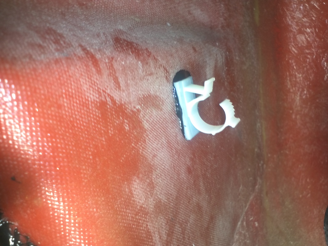
Wire Retaining Clips
These clips came with an adhesive backing, but it would fail after a day or so. So I removed it, hit the surface with 80grit, cleaned and then used 3M8115 to bond them to the inside of the body.
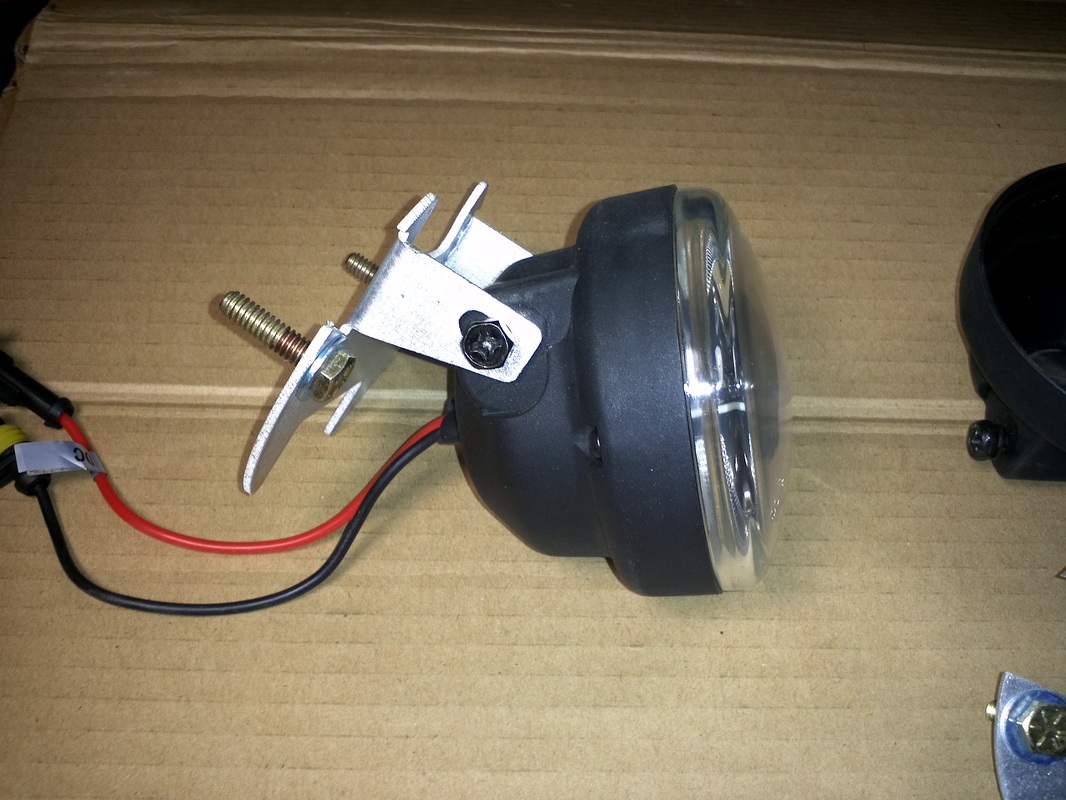
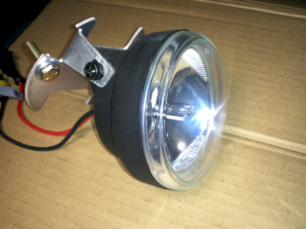
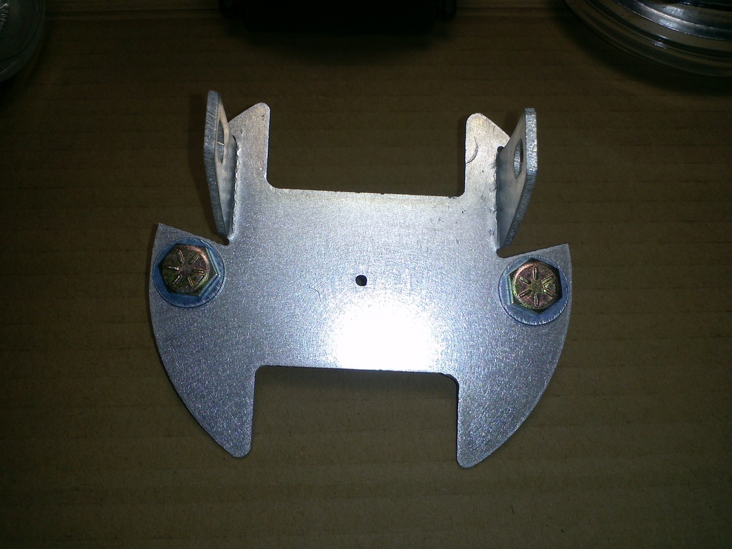
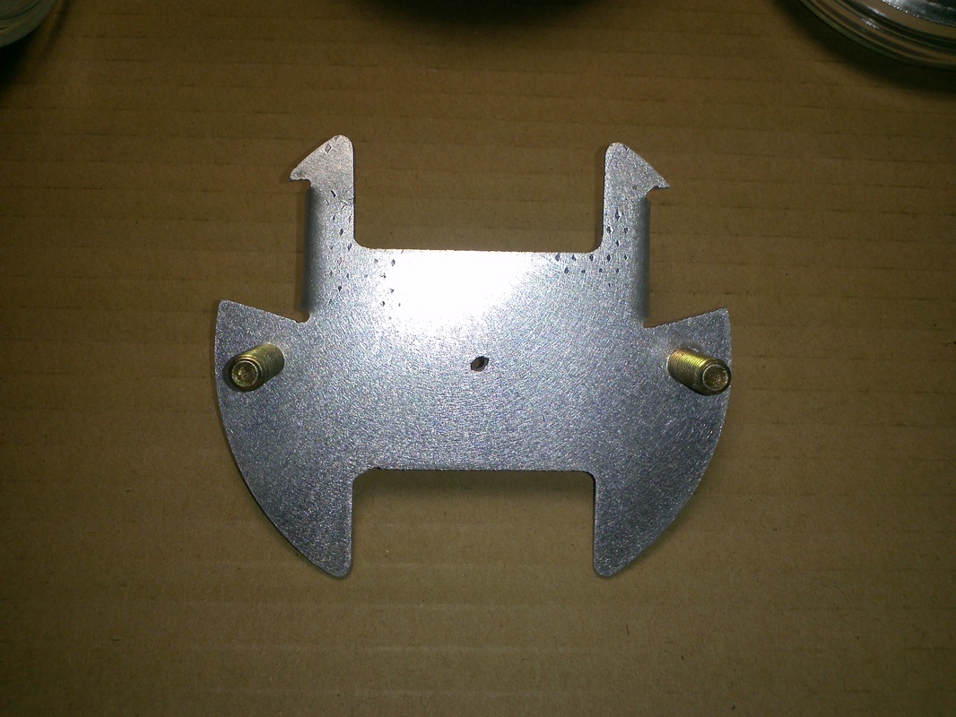
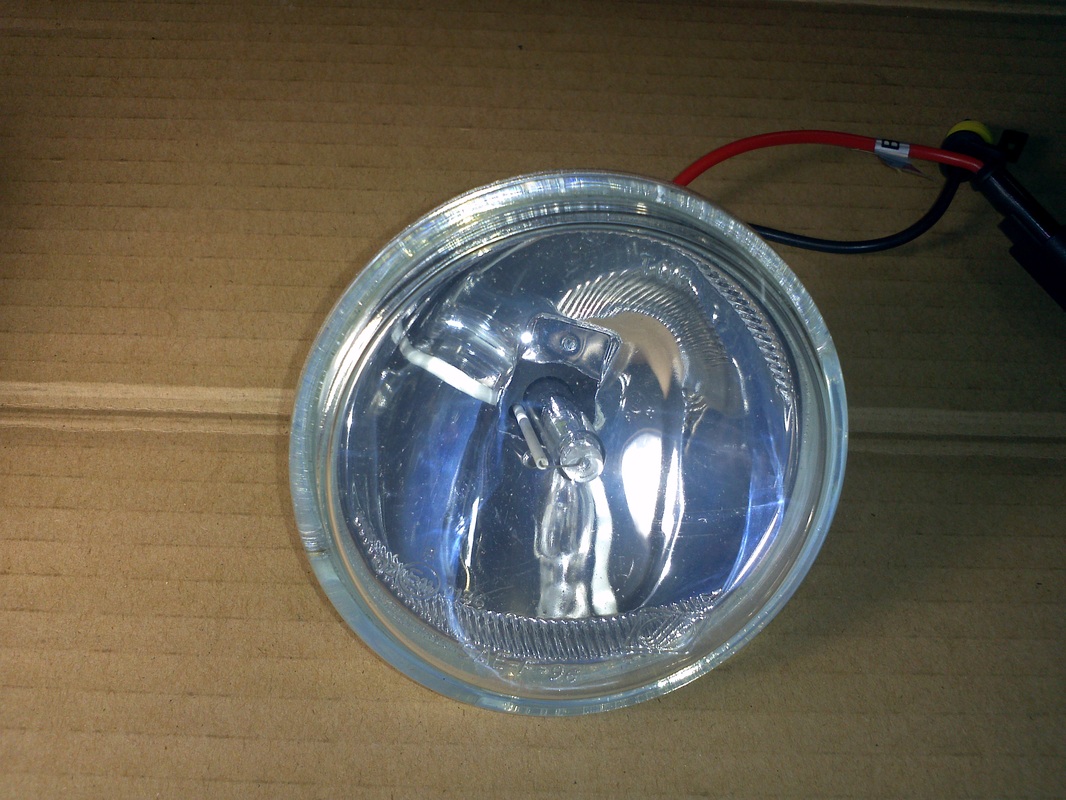
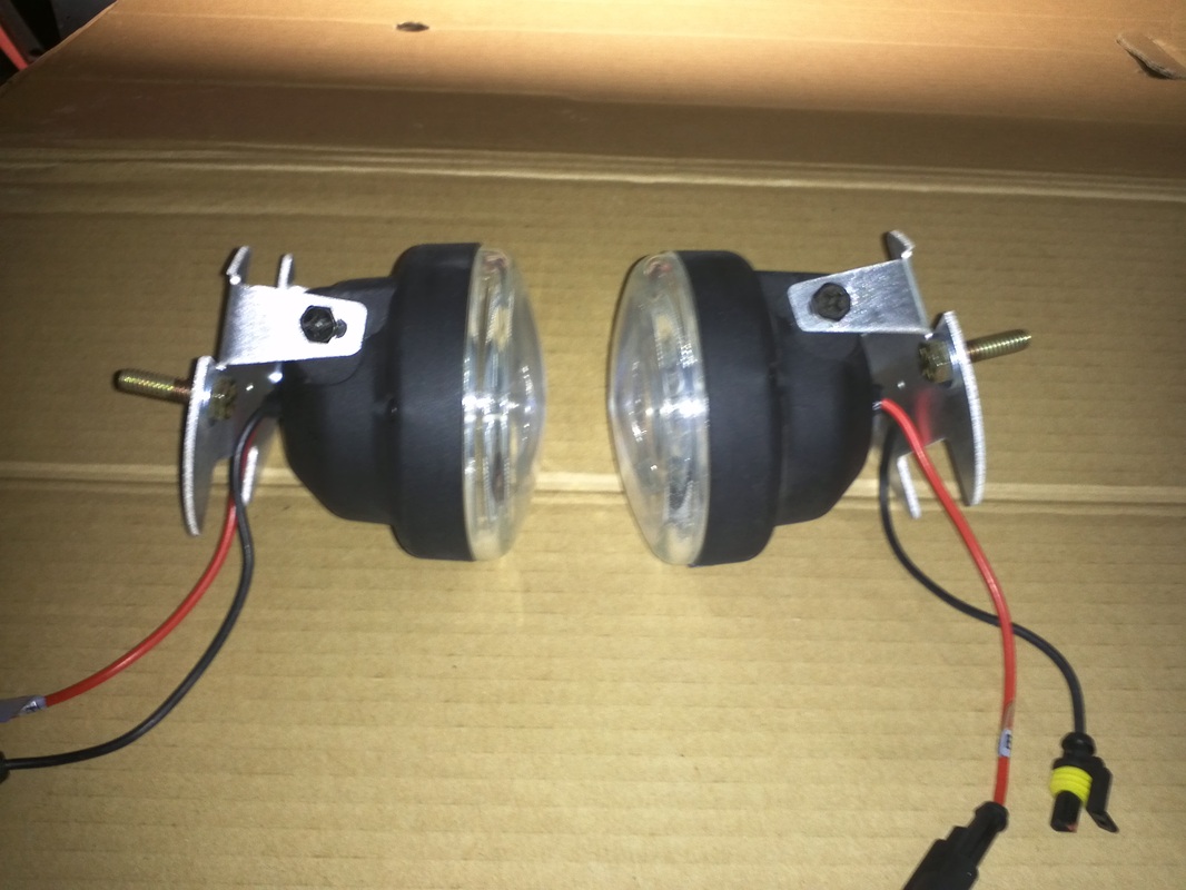
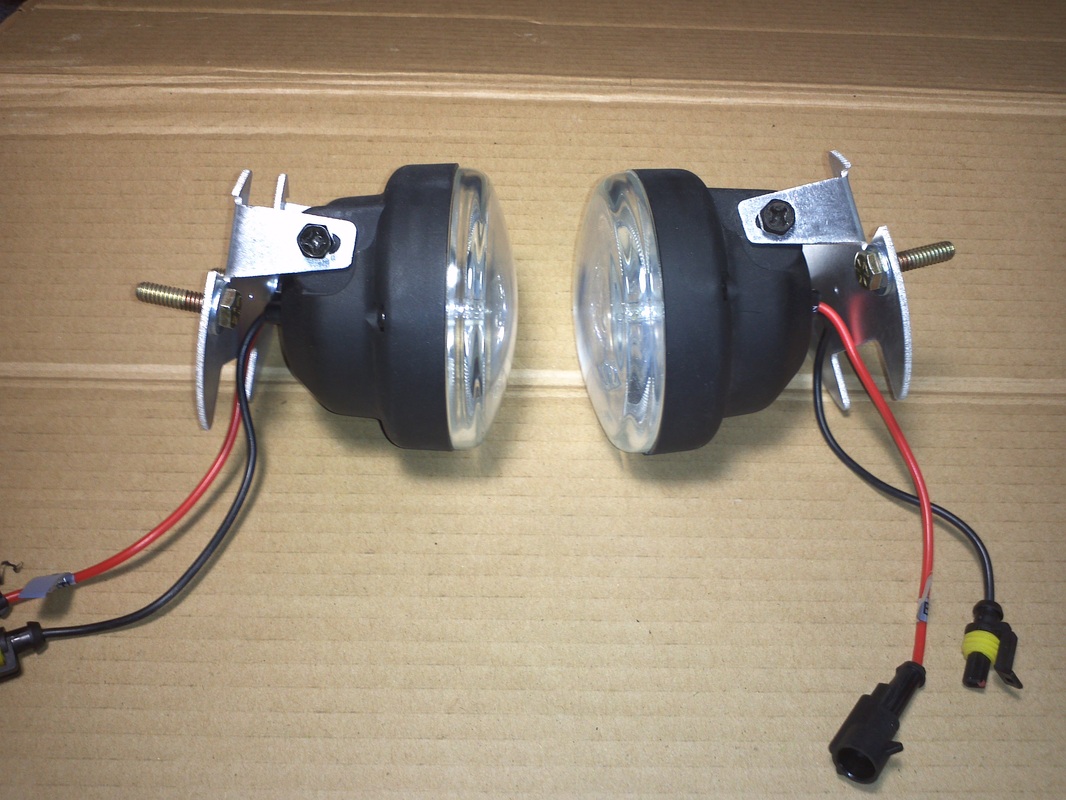
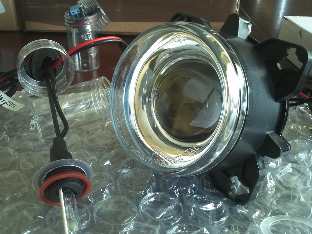
Fog Lights / VRaptor Speedworks GTM Fog Light Mounting Bracket
I contacted Shane and ordered a set of his fog light mounting brackets. Yet another outstanding "problem solver" from Shane. The manual's instruction is a modification of the fog light's bracket. Basically, adding two nutserts and using them to mount the fog light. Shane's design is a self centering unit that puts the mounting points in areas of no interference.
I want to have all of the lighting clean and in the 6000 kelvin spectrum. I was going to replace the halogen with an LED, which would have been a very close match, but the lumen would have been greatly reduced. So I decide to go with a 35w xenon. The fog lights reflector design shoots a horizontal beam. I get the seam horizontal beam with the xenon.
I want to have all of the lighting clean and in the 6000 kelvin spectrum. I was going to replace the halogen with an LED, which would have been a very close match, but the lumen would have been greatly reduced. So I decide to go with a 35w xenon. The fog lights reflector design shoots a horizontal beam. I get the seam horizontal beam with the xenon.

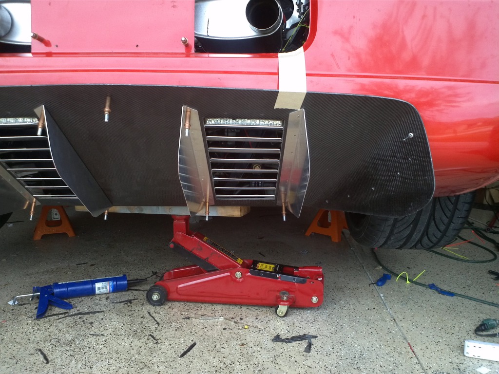
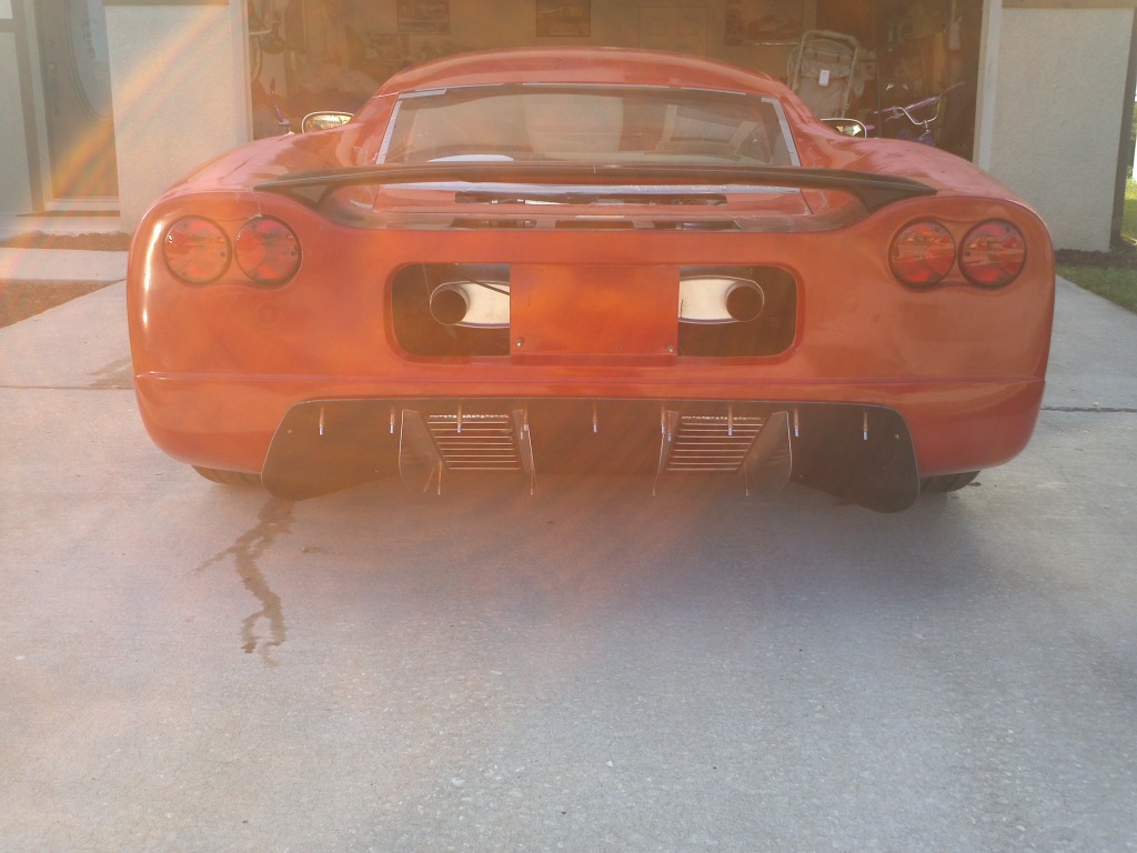
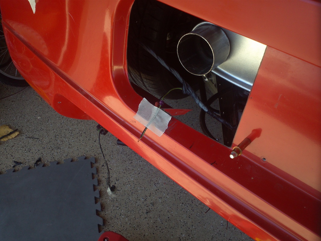
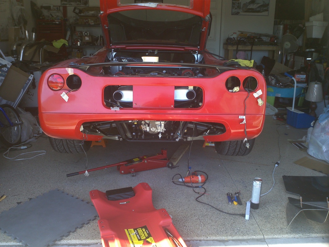
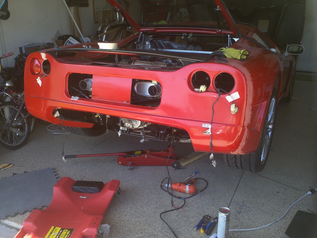
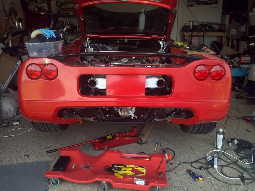
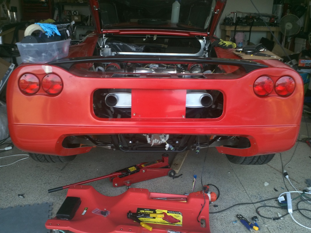
Reverse Light Mock Up
I like the look of having all four lights match. Steve (SK7500) fabricated a set of custom taillights and so was not going to use the included Hella tail light. Thanks Steve. The reverse light was part of the other taillight so I needed to address the reverse light. I thought about creating a cutout/mold in the body, under the reverse lights and then I thought about the C6 corvette. The C6 reverse light is integrated into the diffuser. So I purchased a set of LED Driving lights. I installed them in the top louver opening.
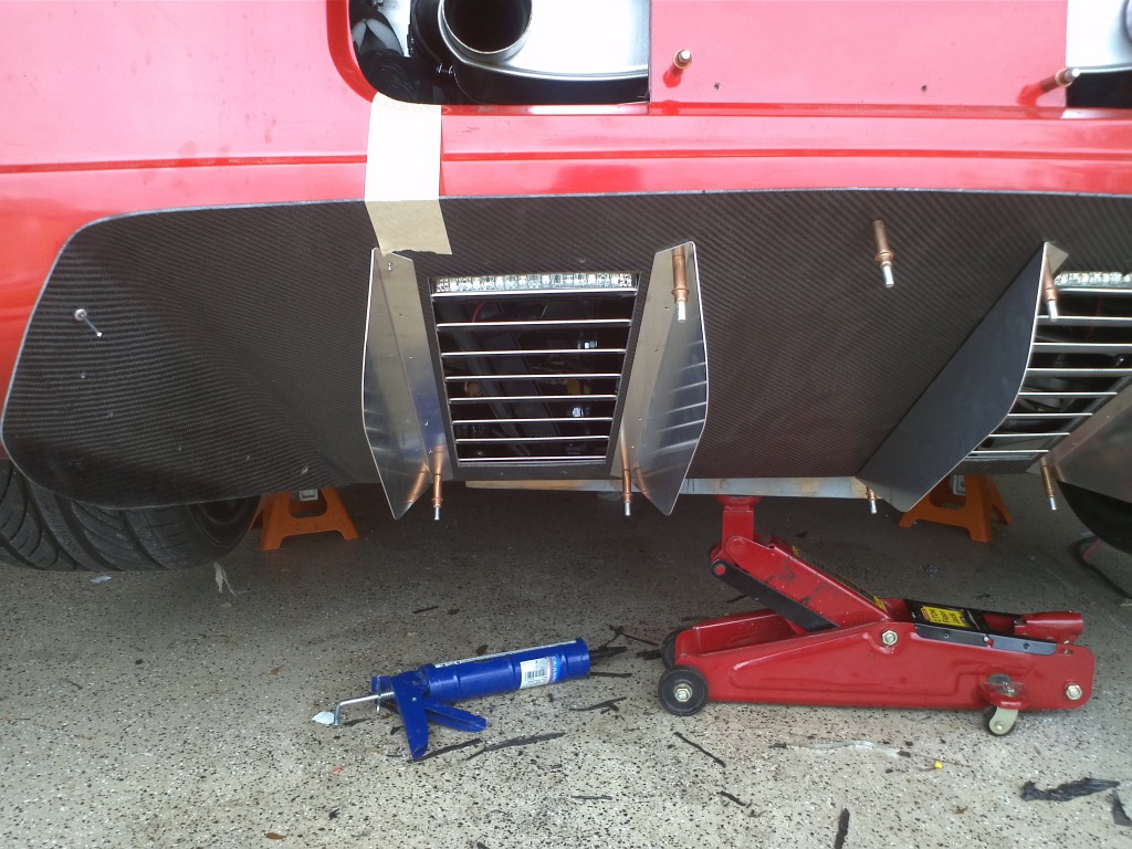
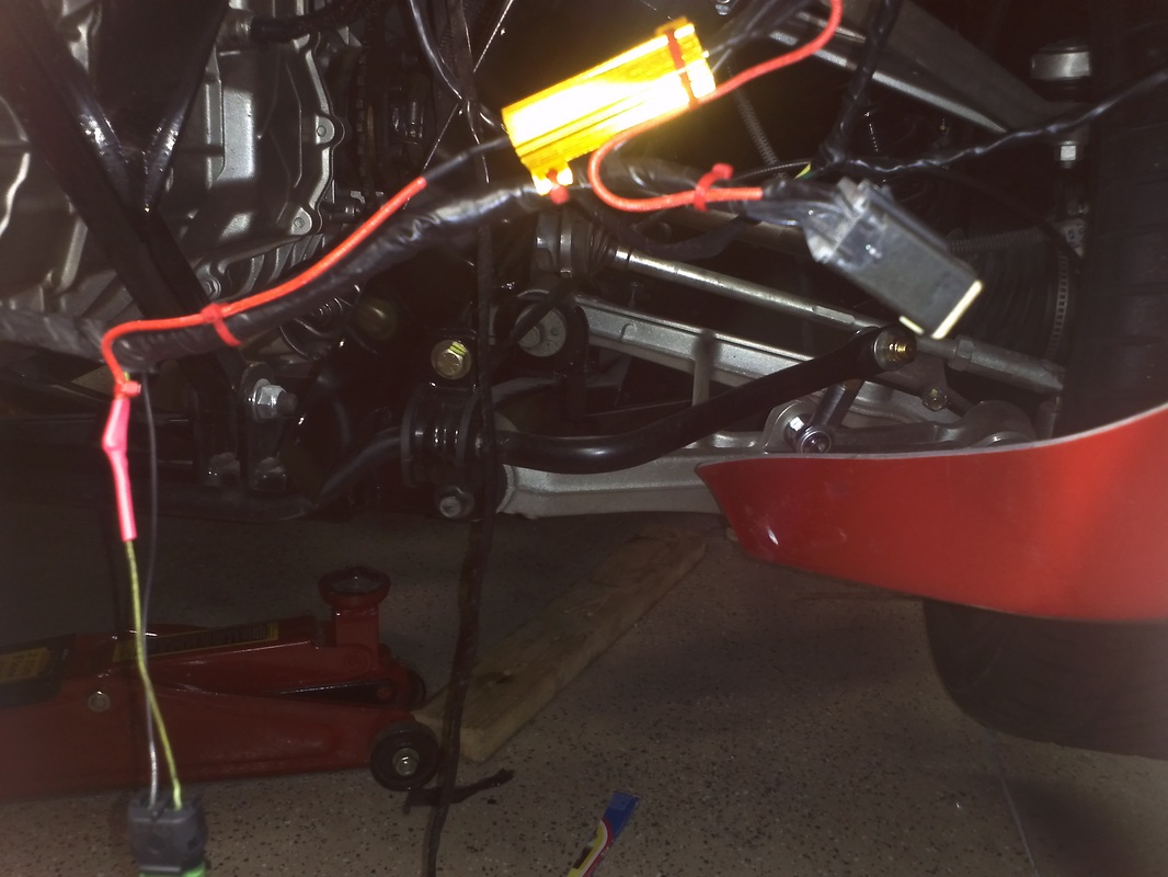
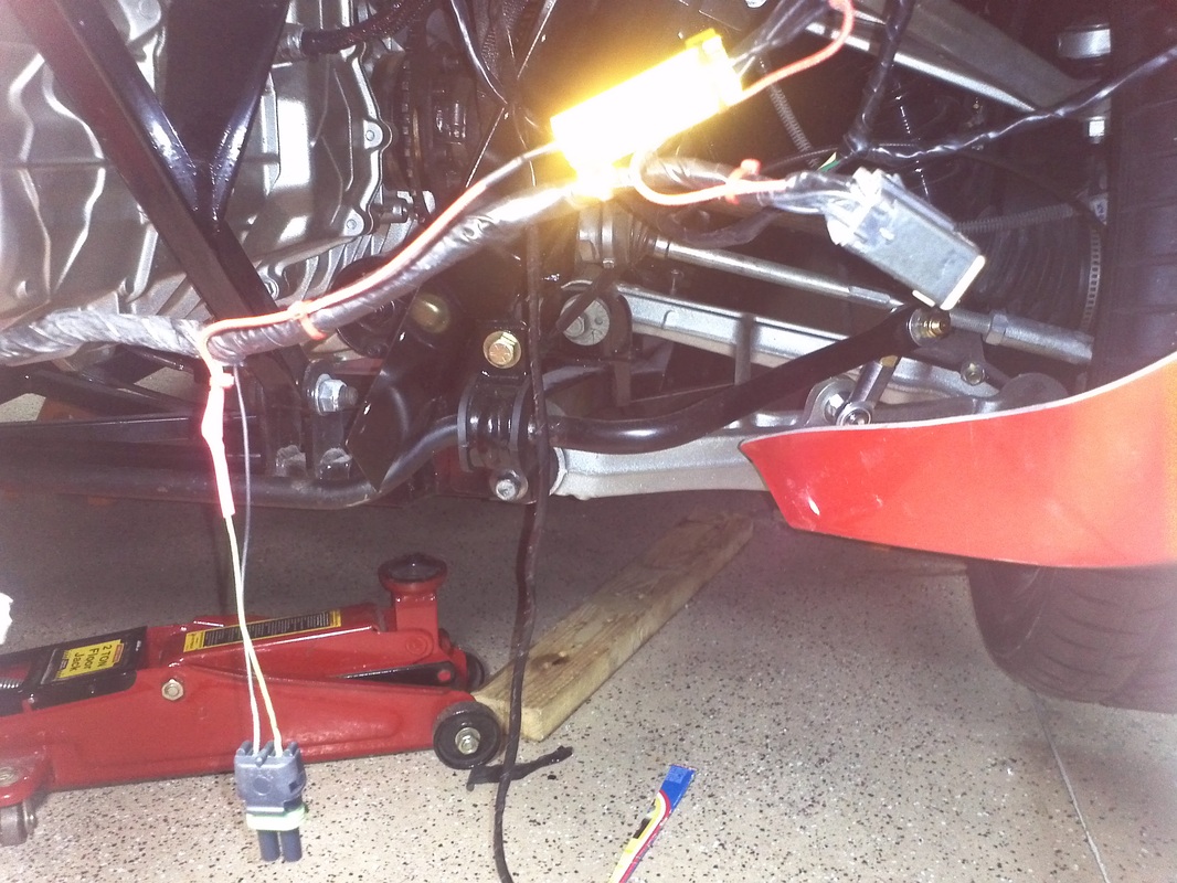
50Watt 6ohm Resister added to Reverse Light Circuit
I added the weather pack connector and discovered that the lights were dimly illuminated when the GTM was on. 6ohms of resistance simulates the resistance of the filament lamp and solves the problem.
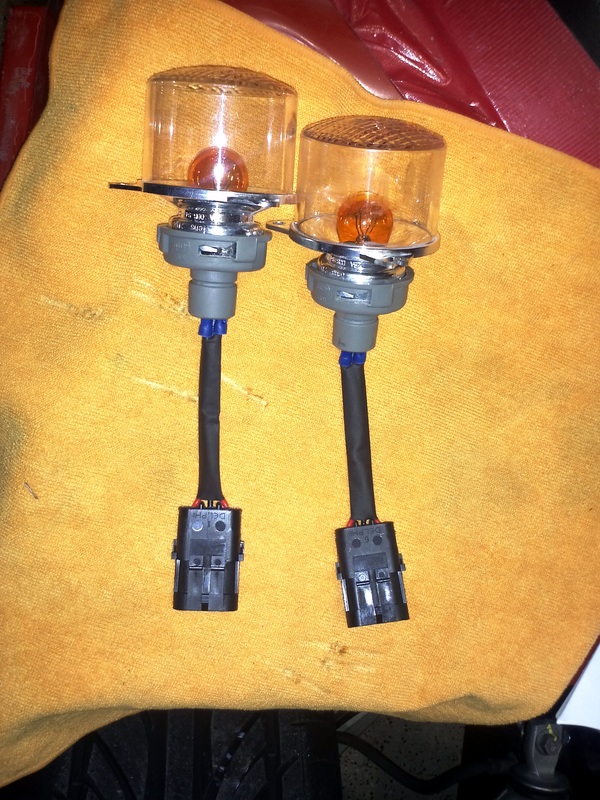
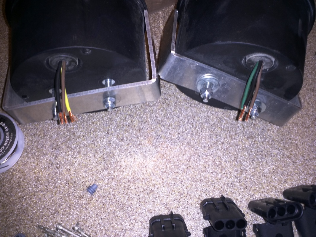
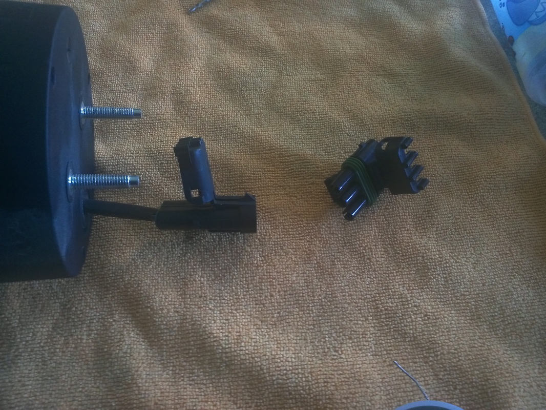
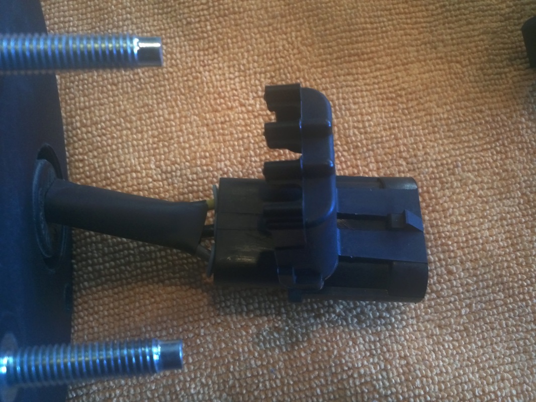
Front Turn Signal Assembly
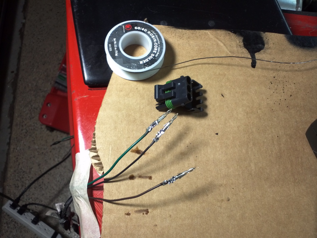
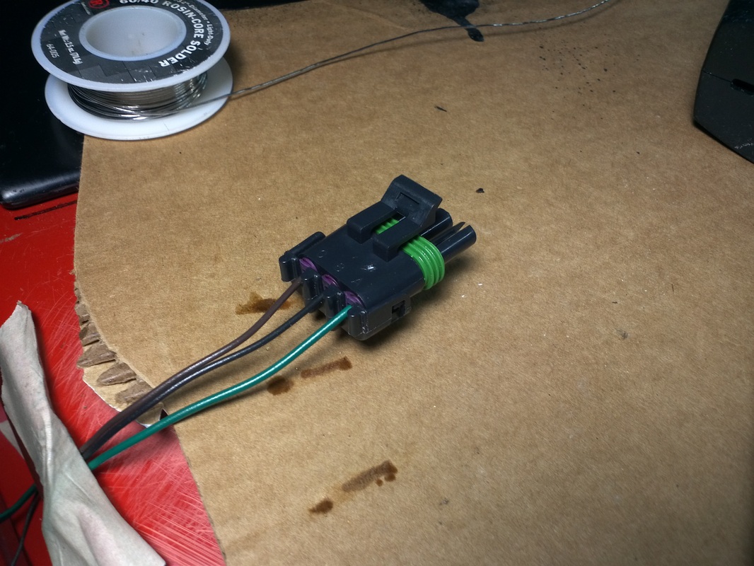
The lamps have three small spade male connectors recessed in the back. The kit includes the small female connectors, however it would be difficult to remove them, if needed, without damaging the connection. I used weather pack connectors here to give a finished look and a standard solution for removal.
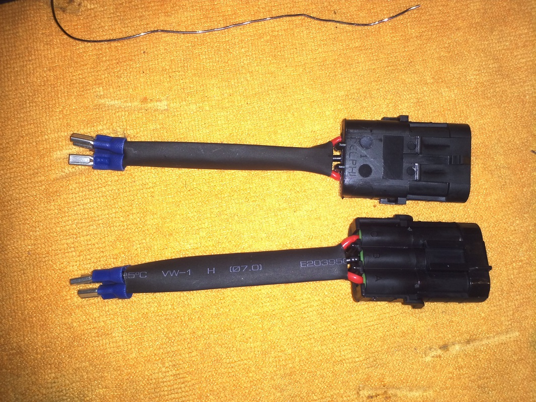
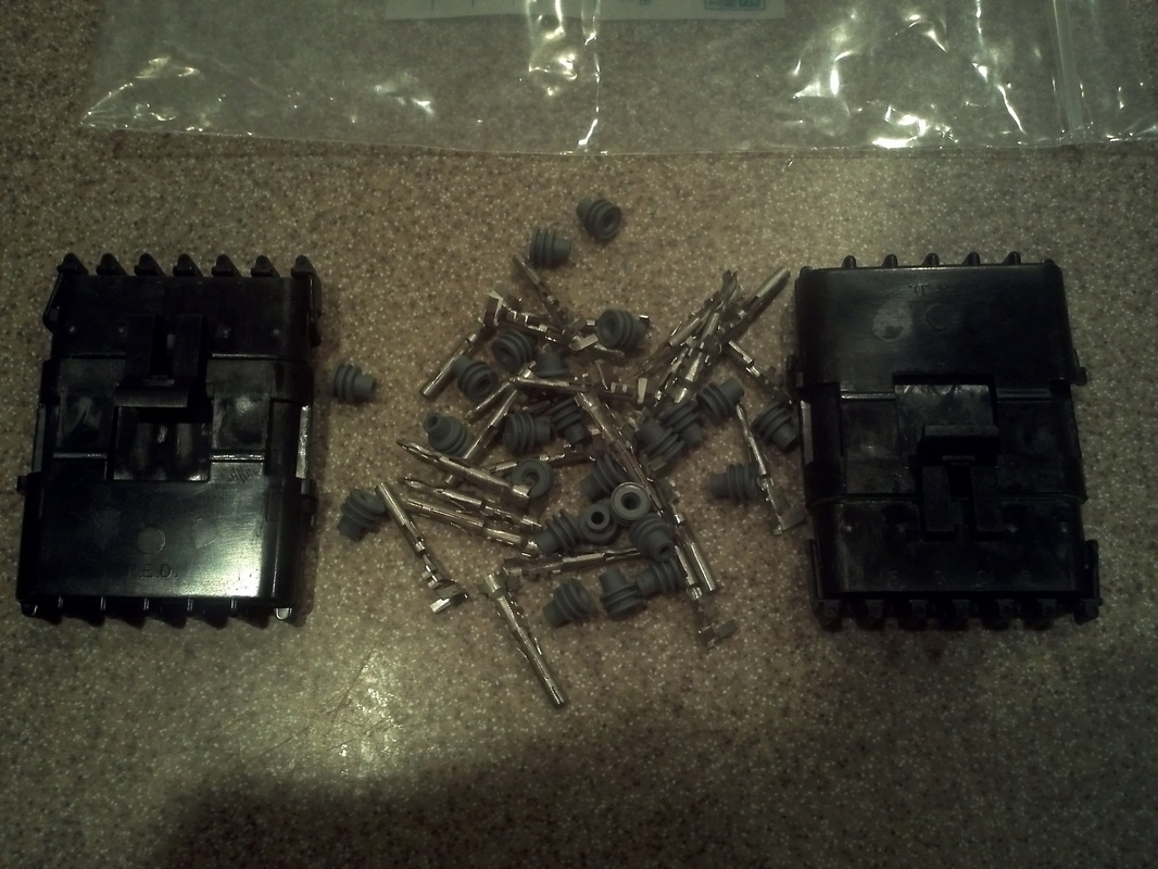
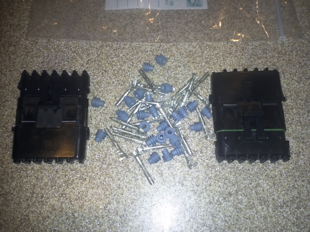
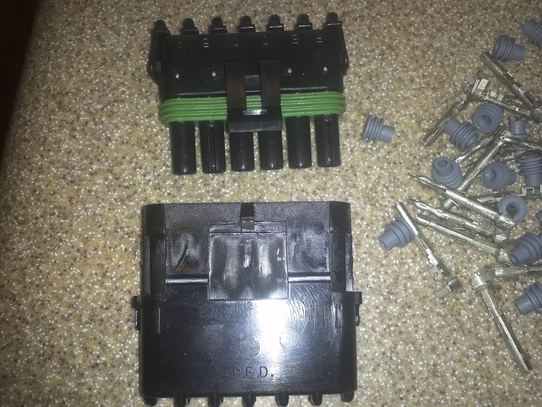
Weather Pack Connectors
I ordered some Delphi Weather Pack Connectors that arrived today. I will use these to do more wire detailing. The donor wiring has a weather pack connector that houses all of the front end lighting with the exception of the head lights, fog lights and horn. I will be adding these to the front so that all of the lighting wiring can be kept with the hood if it needs to be removed. It also makes for a cleaner installation. I am also adding these to the tail lighting as well.

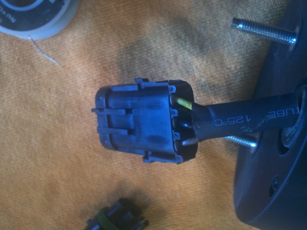
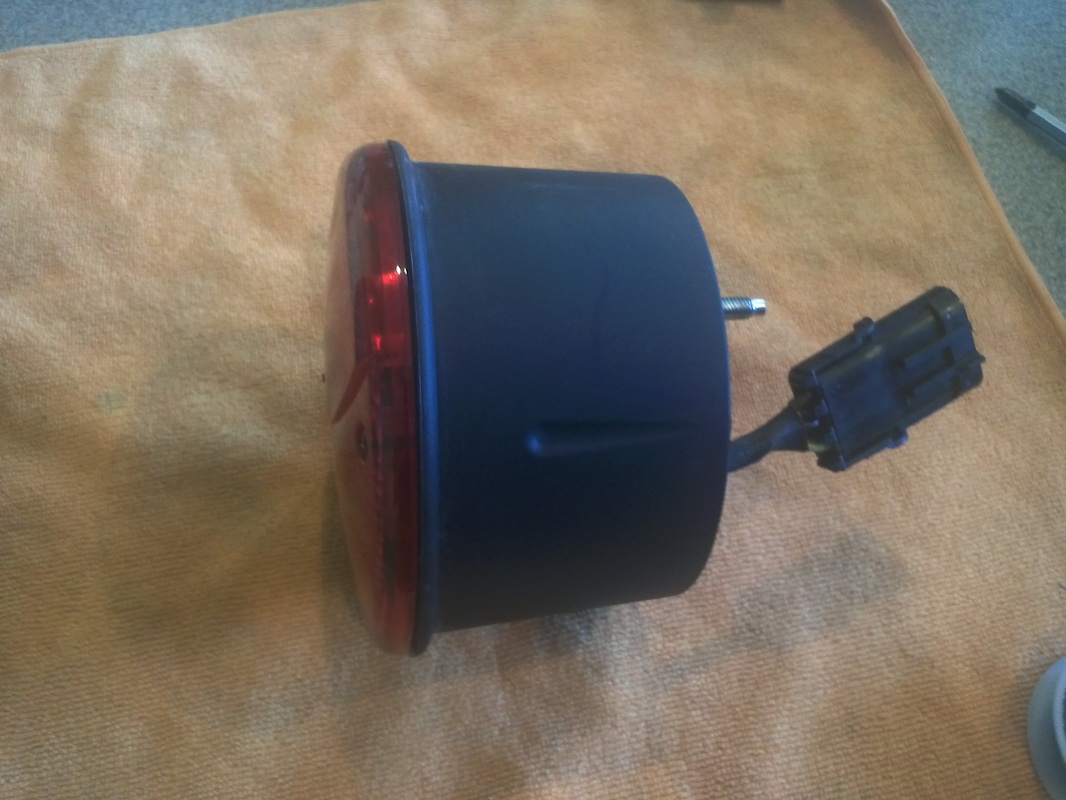
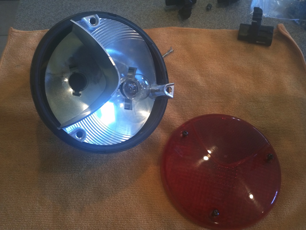
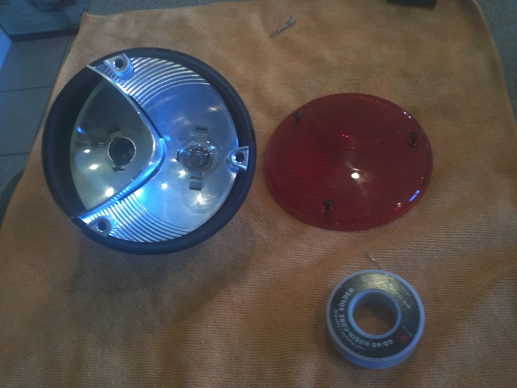
Tail Lamp Assembly
I wired the tail lights using weather pack 3-pin connectors and assembled the lights. I have four of the red lens tail assemblies and I will be using a separate reverse light.

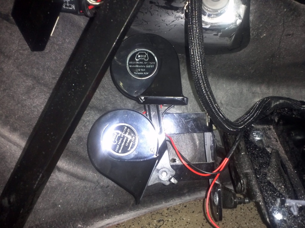
Horn Wire and Mock-Up
My donor's horns stopped working so I purchased a Wolo HI/LO Tone Dual Tone set. I mounted them to the donor horn bracket after removing the stock horns. These are extremely loud.

CAN OR CAN bus is a message-based protocol, designed primarily for automotive applications. The CANBus allows micro-controllers and devices to communicate with each other within the vehicle without a host computer. Each node can send and receive information, though not simultaneously. Information consists primarily of an ID, that represents the priority of the information, and up to eight data bytes. It is transmitted serially onto the bus. Basically the system I have installed from the 2000 C5 corvette consist of Power-train Control Module, Body Control Module and other modules that communicate with each other to carryout the complete operation of the vehicle
Suspension Assembly
Progress
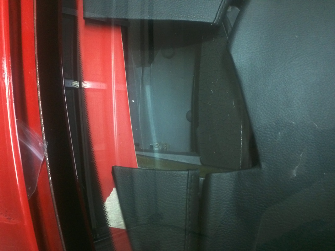
Heads Up Display (HUD)
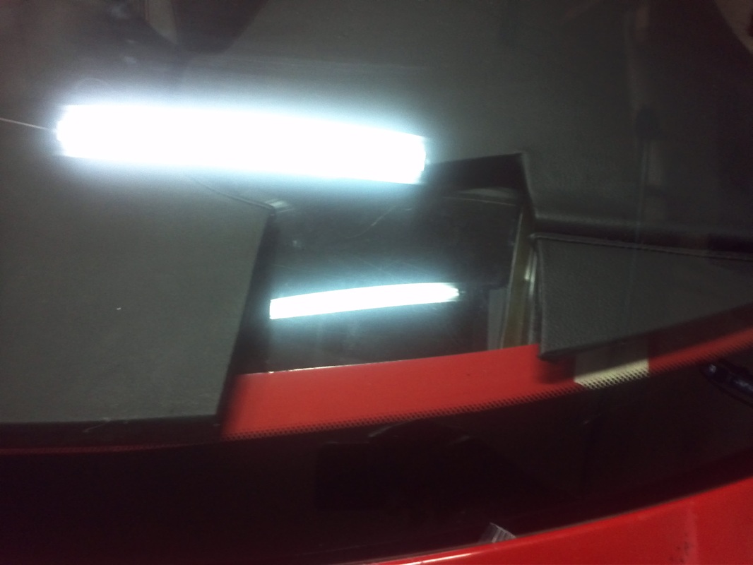
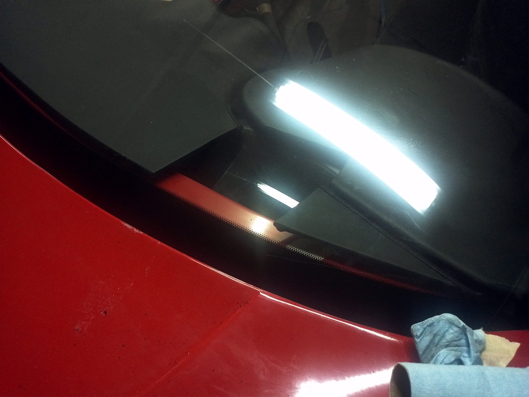
Some test fitting for placement and function. The current position is perfect.The HUD is perfectly centered on the driver and is also just under mid screen vertically. The task will be to complete the dash around the IP and HUD prior to first primer while the windshield is still in place.
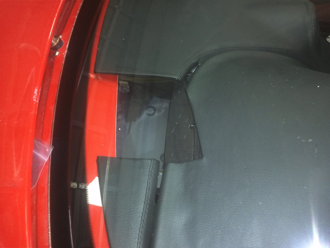
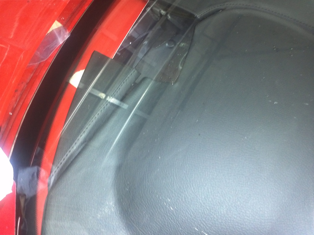
HUD
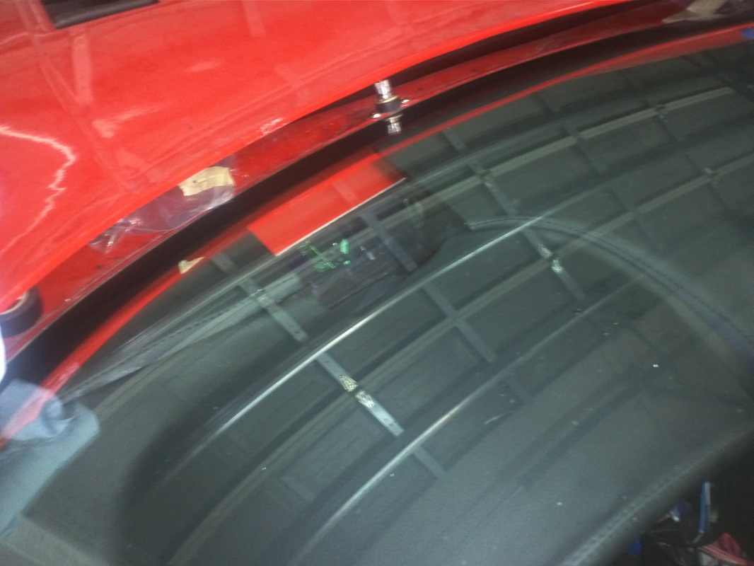
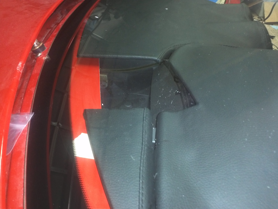
HUD opening cut out of Stock GTM Dash and Stock Material reapplied. After the windsheild is remove I will fabricate a trim bezel.

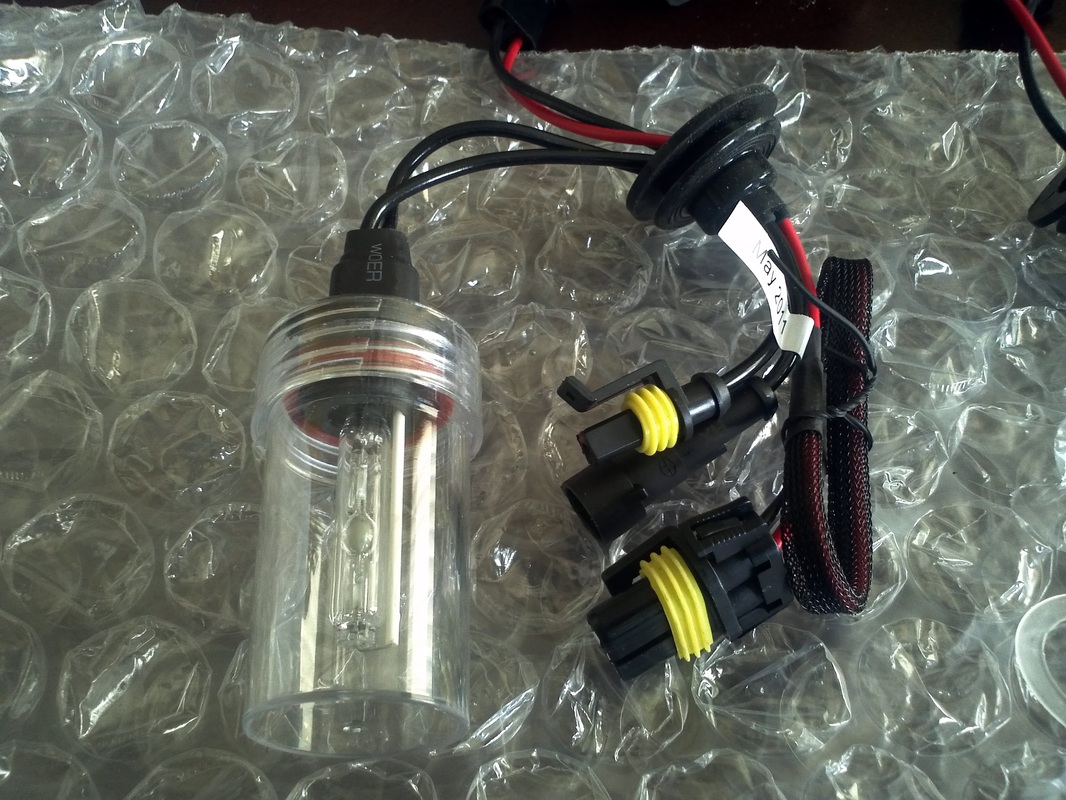
High Intensity Discharge Conversion.
I searched and found an H9 6000k HID conversion kit that carries a one year warranty. This is the 35 watt kit which is recommended for projector/fog housings because of heat. The 35 watt kit is more than bright enough in combination with the projector lens.


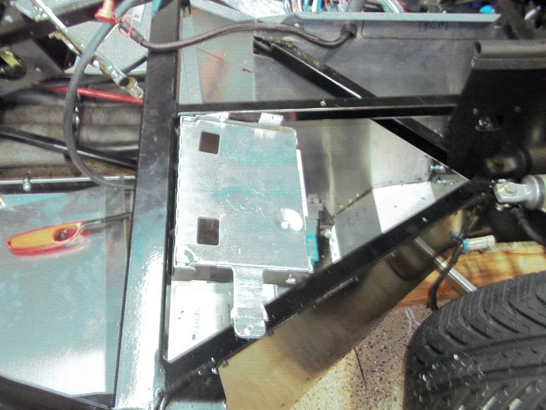
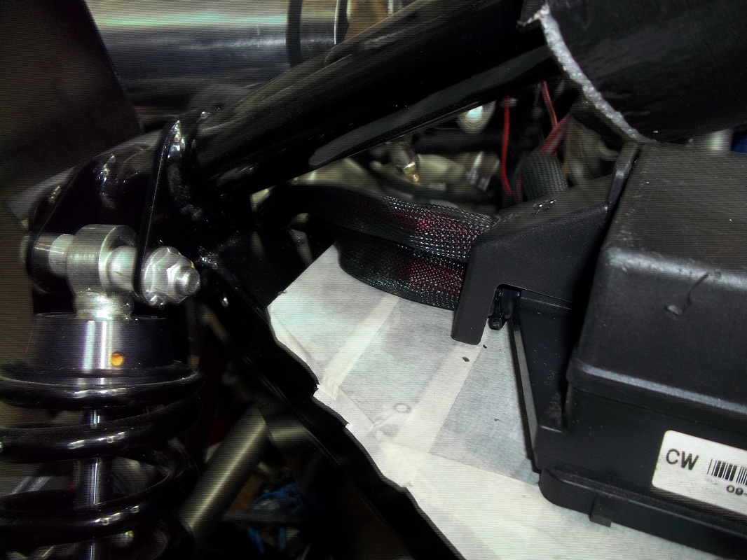
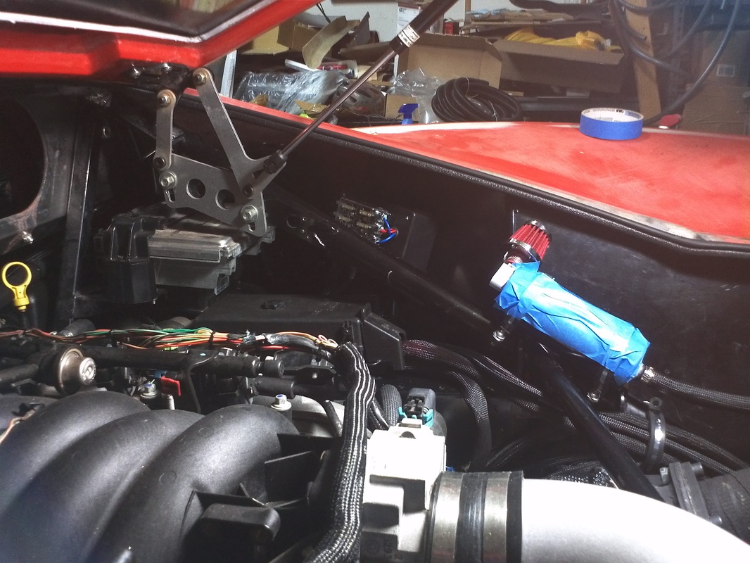
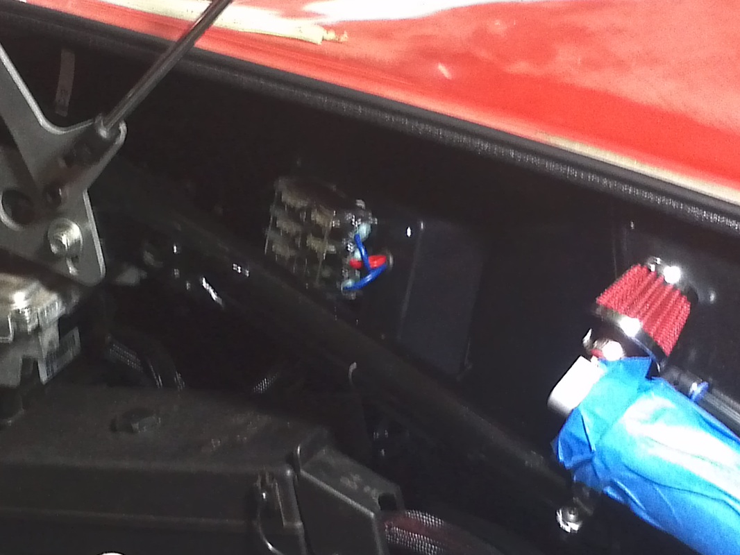
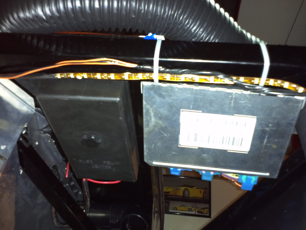
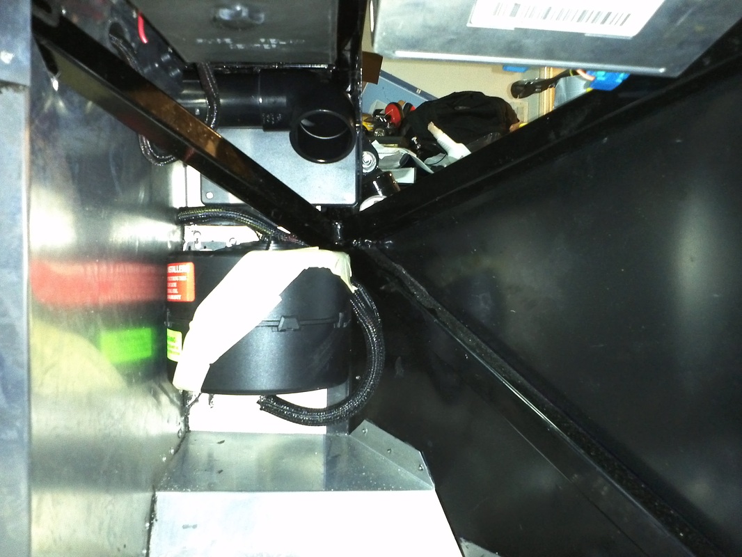
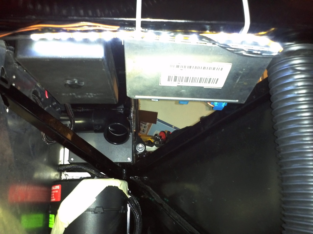
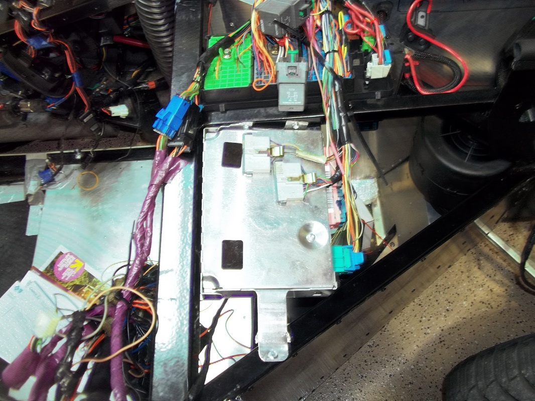
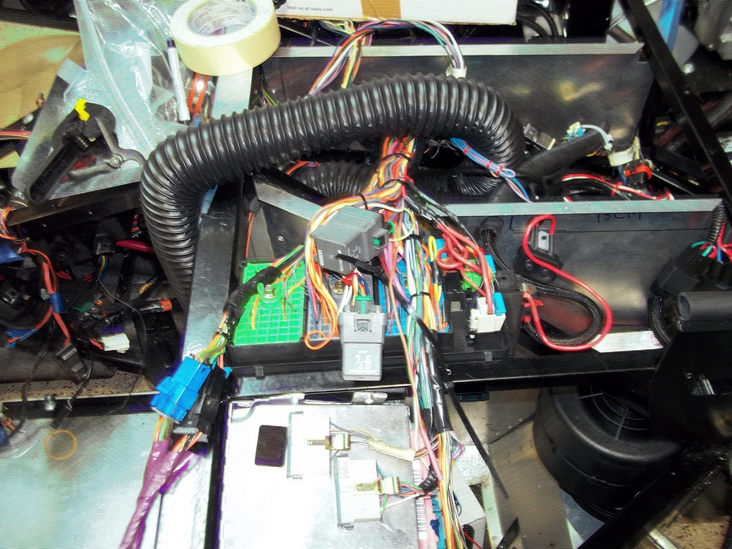
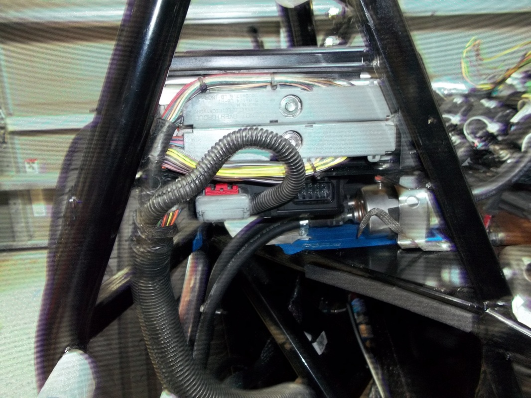
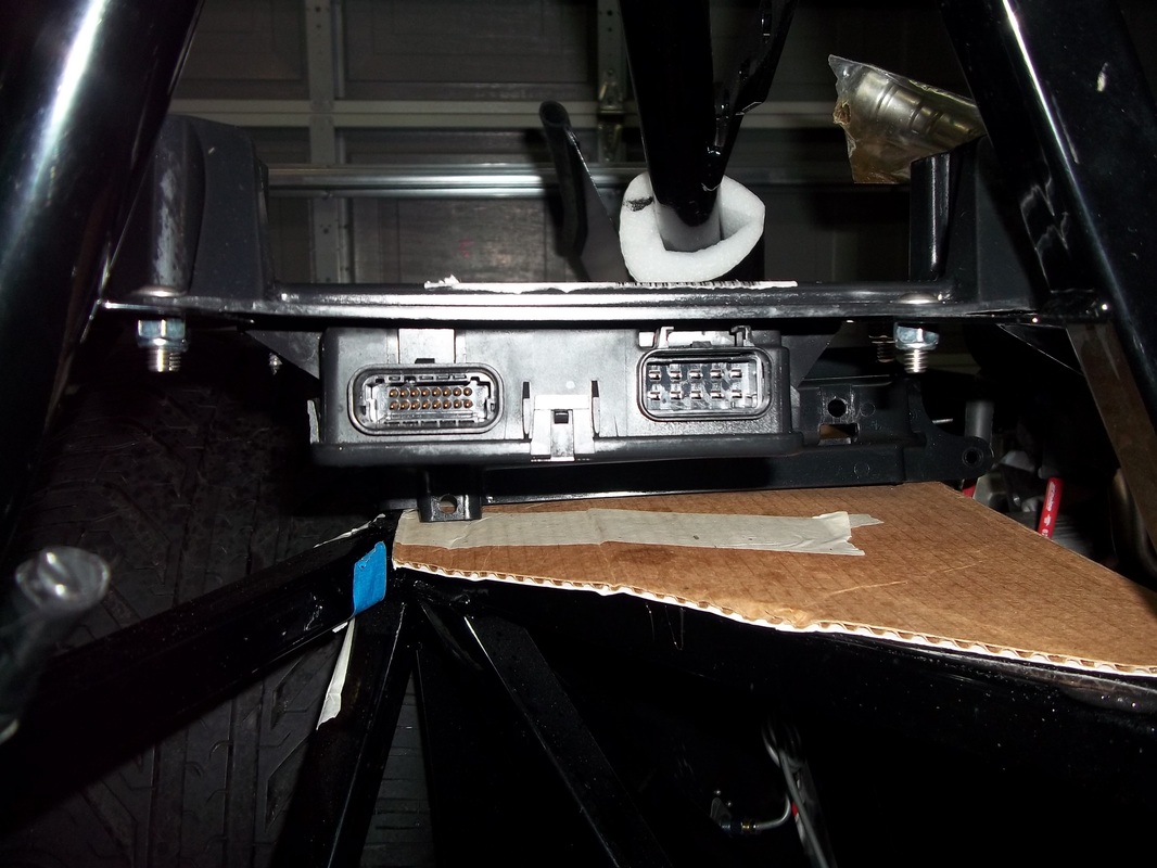
Interior Fuse Panel and Body Control Module (BCM). Twilight Sentenial Light Sensor. Electronic Access Box.
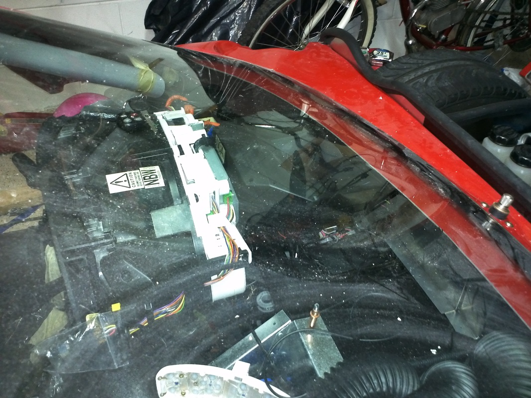
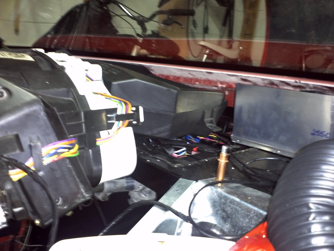
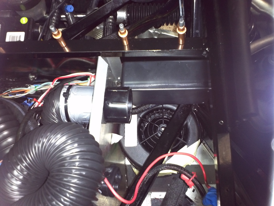
With the majority of the wiring done, and the top tunnel cover installed The interior fuse panel and BCM are secured and their wiring reconnected. Both the interior fuse panel and the BCM are no lower that 3/4" at their lowest pint. The passenger side dash should conceal them from view. The light sensor for the twilight sentential function is taped to the top panel for now. it will be installed in the side of one of the windshield defroster vents or center of dash. The electronic access box is secured to the passenger foot box wall immediately above the HVAC blower motor. It contains the HVAC relays and some electronics Termination that is communicating with the bus. See details here.


Remote Frequency Identification (RFID) Push Button Startwith Security and Passive Keyless Entry (PKE).
Installed the push button start. It has RFID for added security and PKE for automatic lock/unlock of the doors. The RF transmitter also function like a standard fob in I choose the option and for the hatch release. It functions like the majority of production vehicle systems with a few added features that are needed for aftermarket installation. While pressing the brake (and clutch) a tap press of the start button turns on the ignition and then activates the starter to start the car. If you hold the start button for a second or more the system will activate the starter in "long/cold start mode" which activates the starter for a longer period to accomidate a cold vehicle or hard start situation. Once started, a press of the start button while pressing the brake shuts the engine off. pressing the start button alone once powers on the Accessory circuit. The next press powers the Accessory and Ignition Circuits and the third press shuts them off.
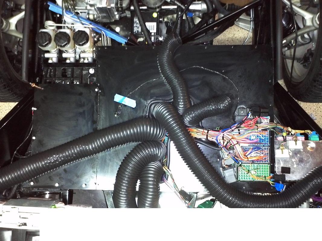
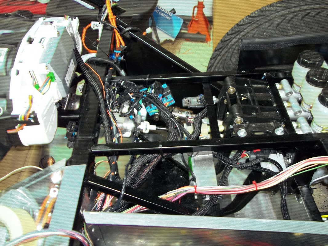
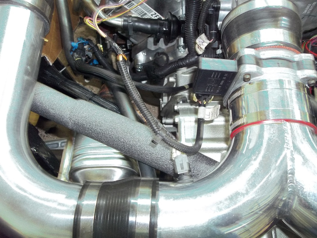
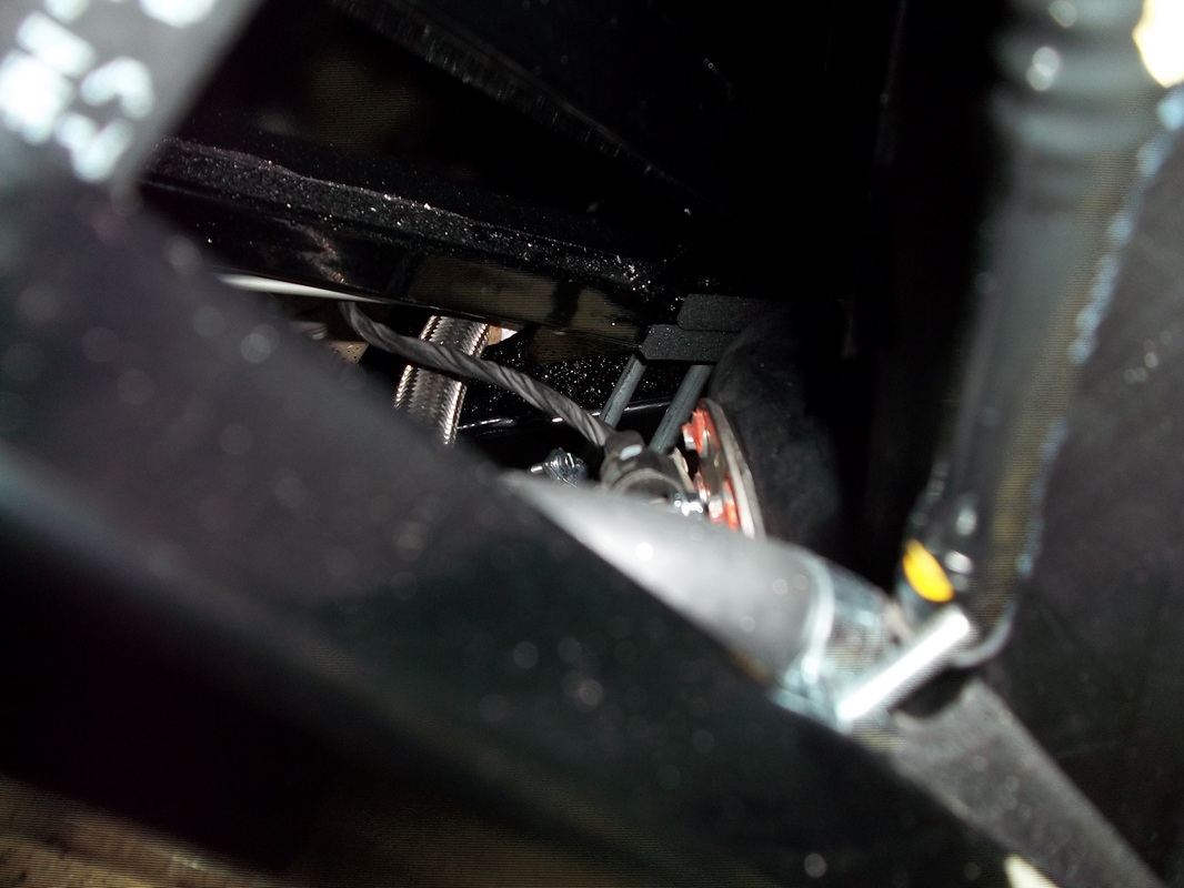
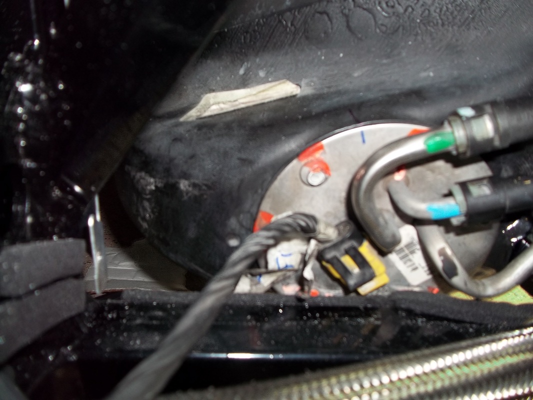
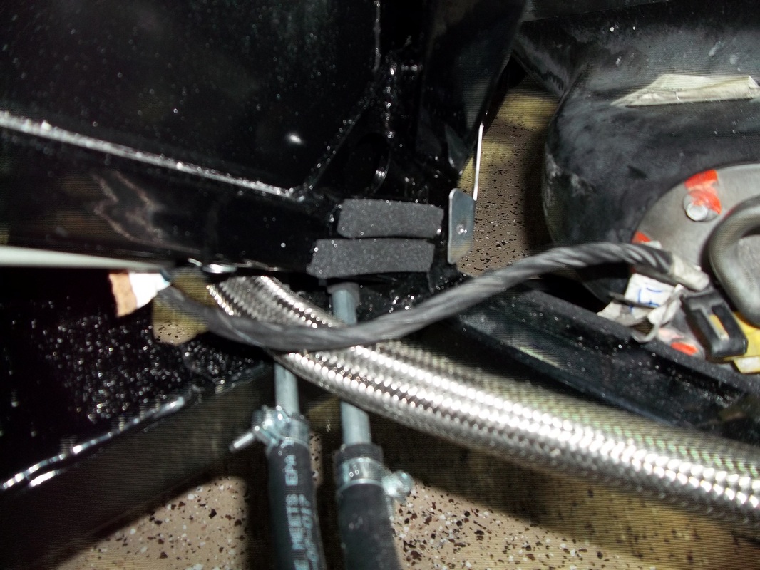
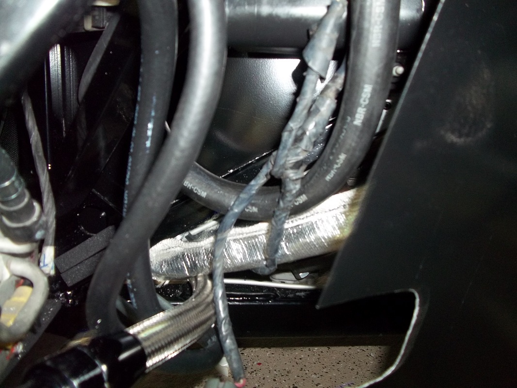
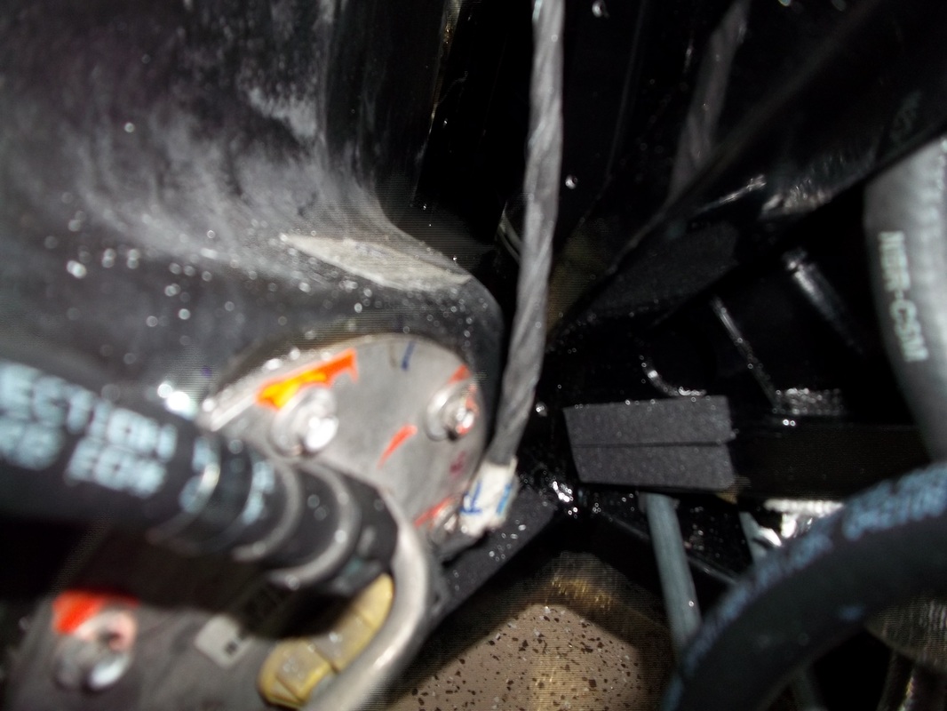
Wire detailing/securing.
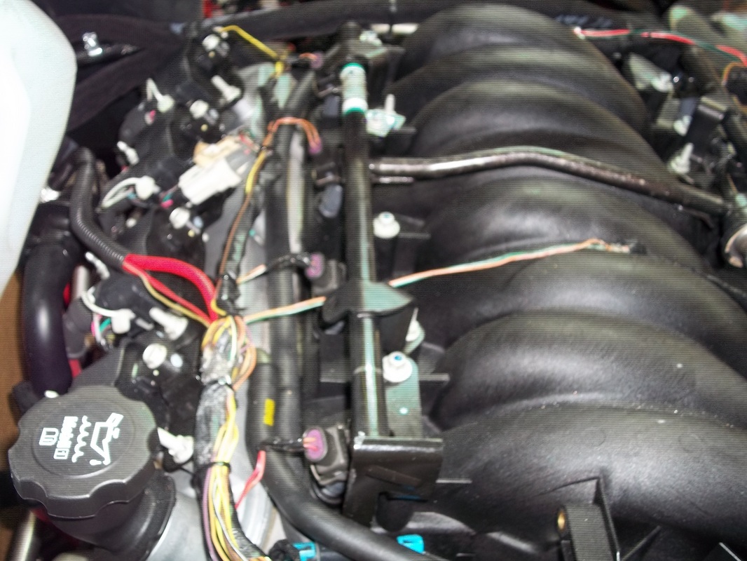
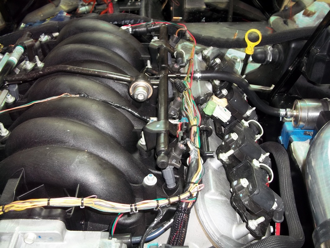
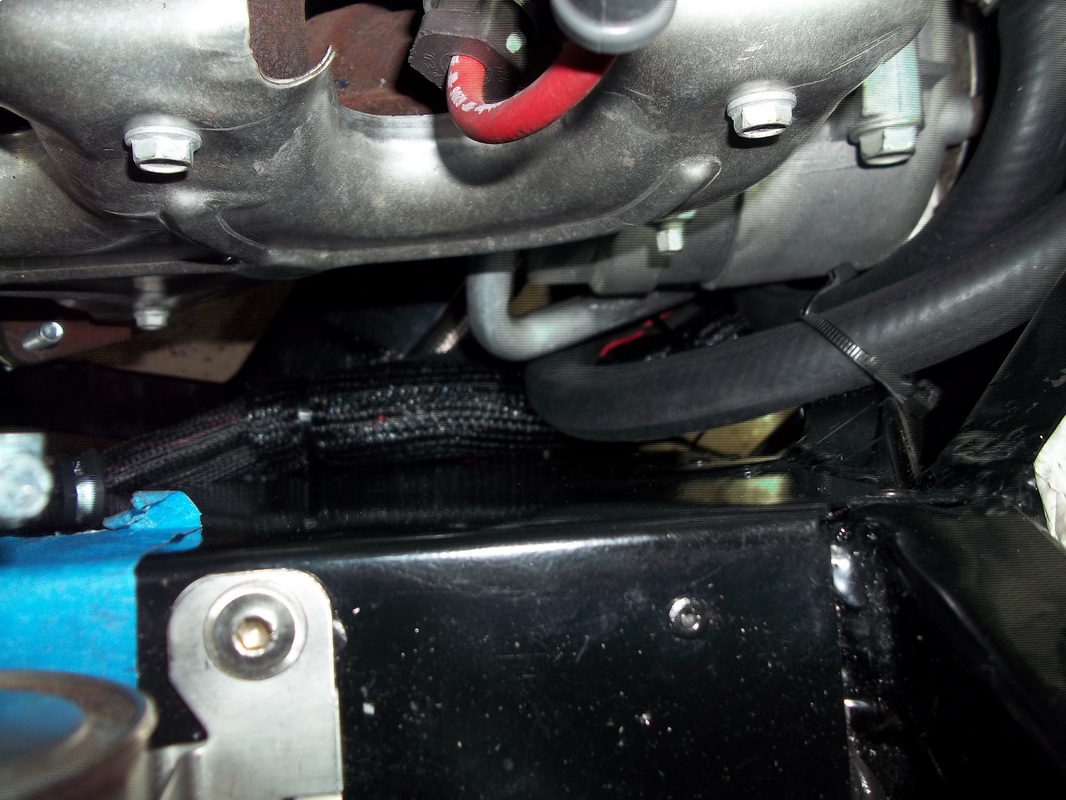
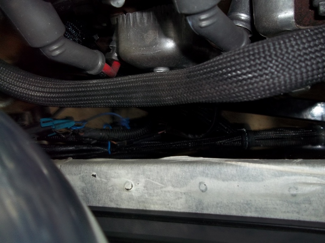
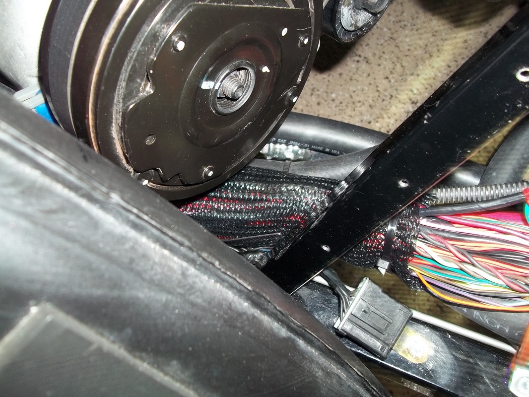
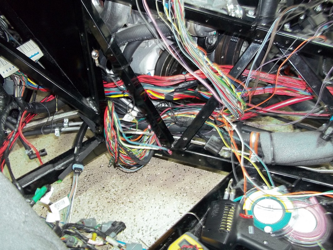
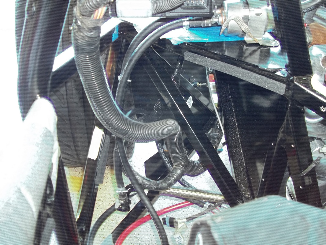
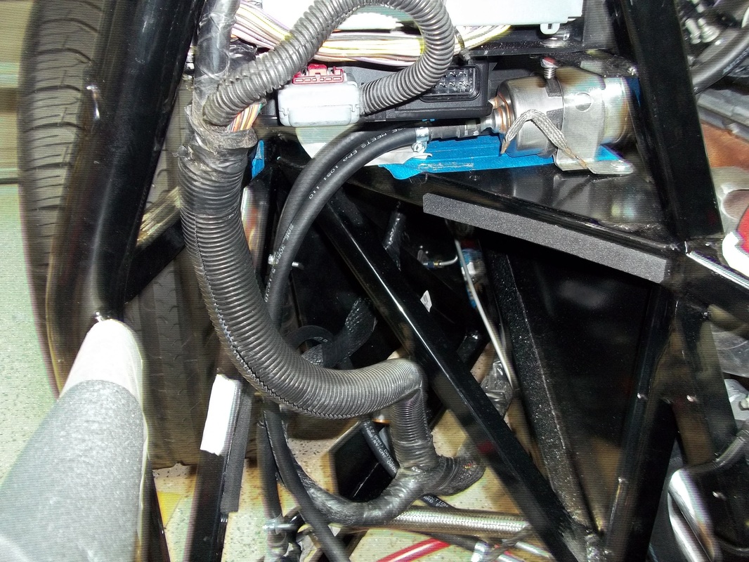
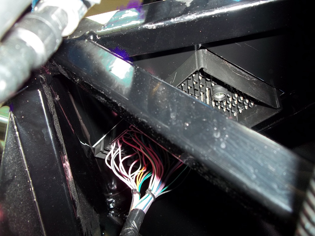
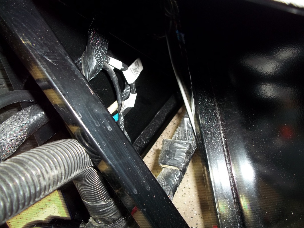
I began the task of detailing and securing the wiring at the passenger side fuel tank area. I then made my way into the engine bay and forward into the tunnel. The goal is to have a clean high-end OEM look. To achieve this I am using the braided sleeve in all of the areas that will/may be visible. Special care and attention to detail is required to get that look and to ensure every wire is clear of any hazards such as exhaust and moving parts. The wiring along the fuel rails will be covered by Mike's Carbon Fiber Engine Cover so I did not cover it with braided sleeve. I have completed the engine bay with the exception of the rear-end lighting which is currently secured to the frame awaiting the addition of the lights.


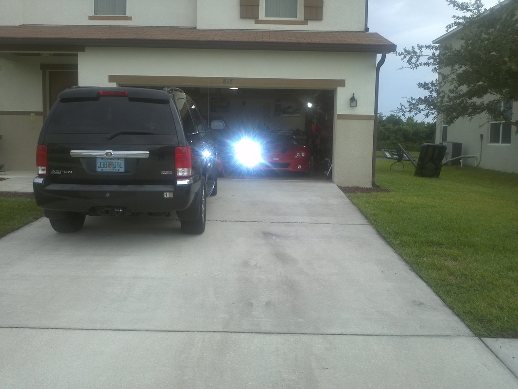
Successful First Start and Long Idle
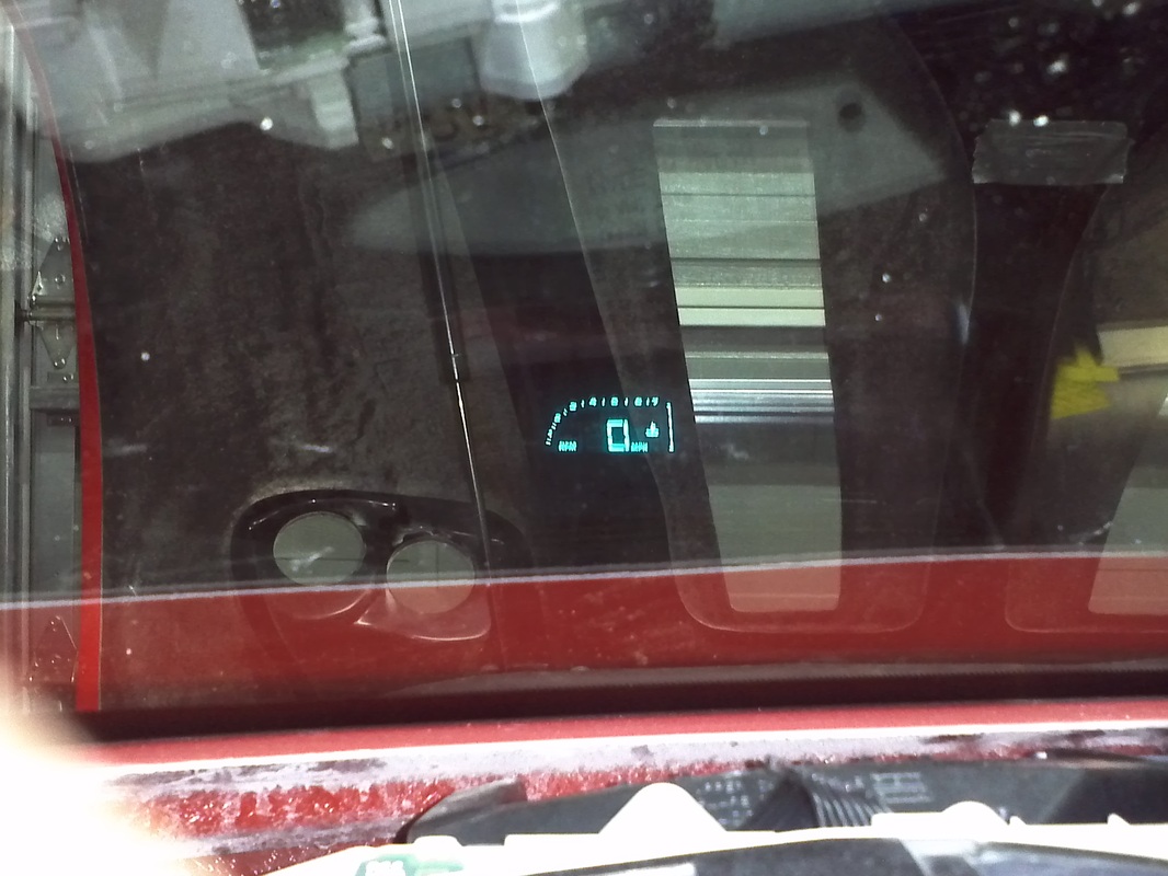
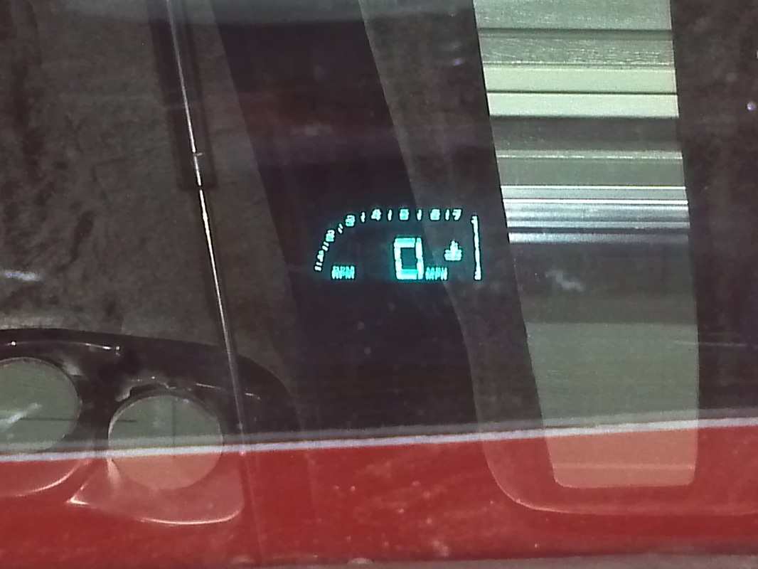
C5 Corvette Instrument Panel (IP) in Gen2 GTM 26 April 2011
All of the C5 Systems have been incorparated into my build. Wth the LS6 running you can monitor every system as if everything was still in my donor C5 Corvette.
|
C5 Corvette Instrument Panel (IP) in Gen2 GTM October 2011
Quick IP Video following Custom IP completion.
|
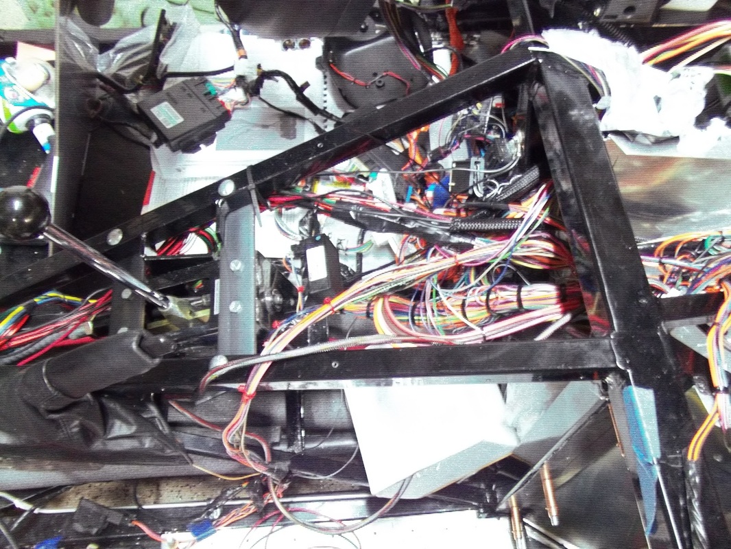
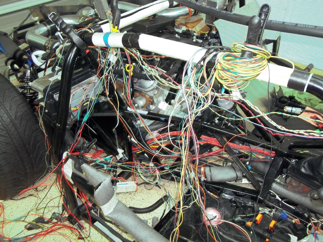
More Wiring and first start attempt.
The majority of the wiring is roughed in. I still need to make a few solder connections like the light harnesses and the AC connections. I did not expect to progress this quickly and had planned for a first start/attempt next week-end. However, I found myself only needing to connect the clutch pedal pressed input to turn over the engine. After getting a diagram form LSMan I was in business. I cleco'd the compressor panel in place, secured the passenger tank connections and put 4 gallons of fuel in. Since the engine and PCM are not from my donor and from a ZO6 a PCM/BCM password sync was required. Its a 30 plus minute process. I had completed this earlier. Now for the start attempt. I turned the ignition to start and the engine fired but did not start. After some further research it appears that I have a security/vats/column lock issue. OF the three I suspect the column lock. If the correct criteria are not met the PCM shuts off fuel and or will not allow the starter to engage. The only real fix for this is to turn it off with an HP Tuner. I should have my tuner middle to end of the week.
Once its running I will finalize/secure the wiring and start preparing for go karting.
Once its running I will finalize/secure the wiring and start preparing for go karting.
More Wiring and Some System Checks.
After installing the BCM, Instrument Panel/ Gauge Cluster I powered up the IP to test my work thus far. It powered up perfectly. There are about 12 DTCs but that's expected as the majority of them are there because a module is not there to communicate with the system.
Most Systems Connected
I have the majority of the Major and minor systems connected. Powered up the IP and now have only five DTCs. Two of them I will either turn of with my to be purchased HP tuner or electronically trick the system for the required input.
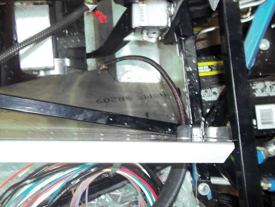
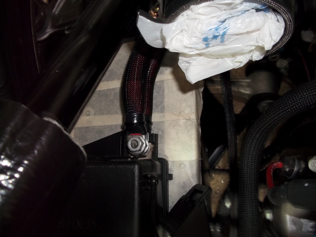
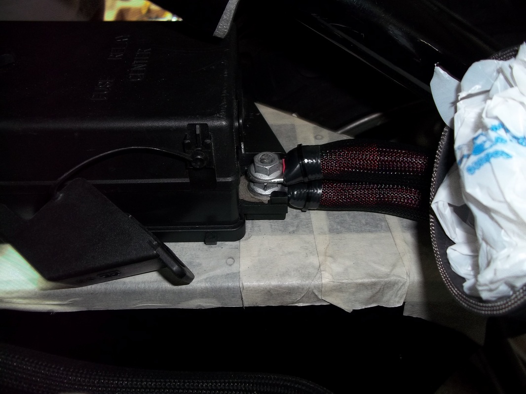
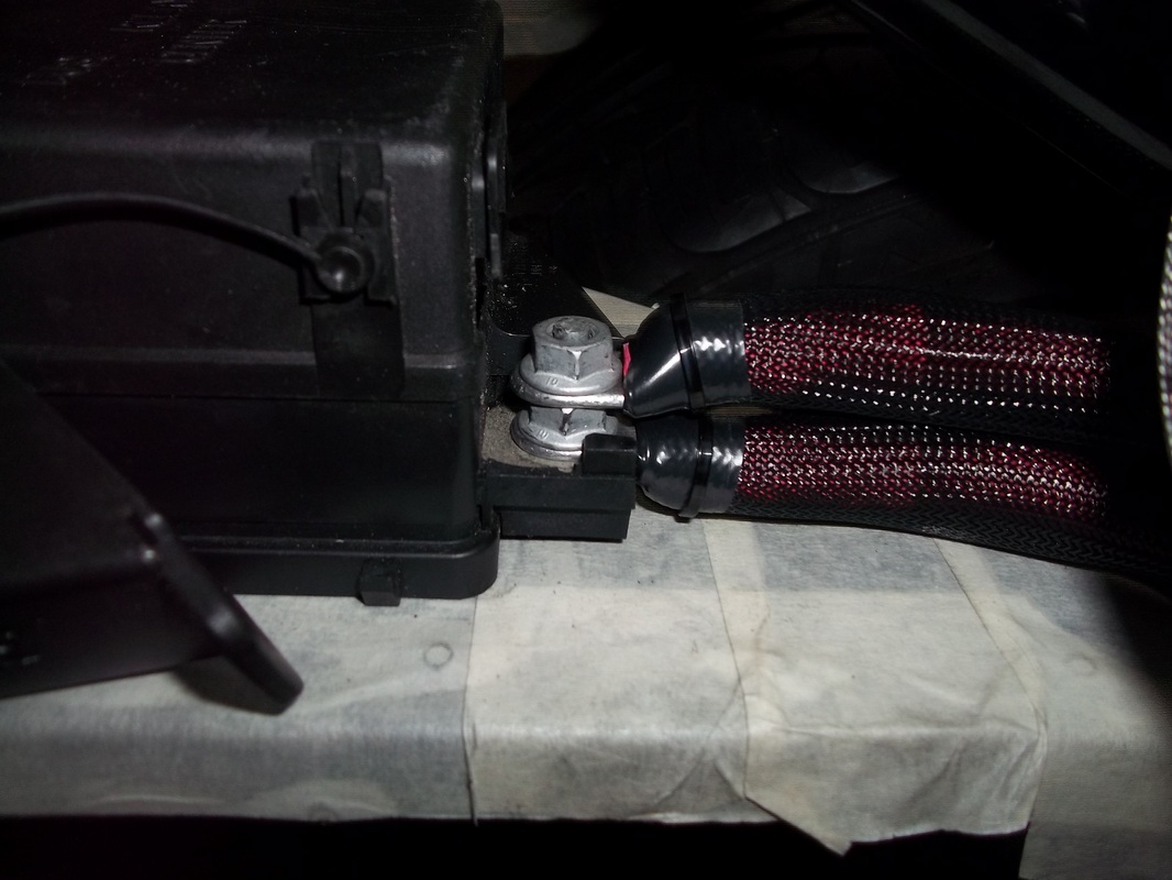
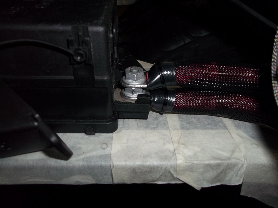
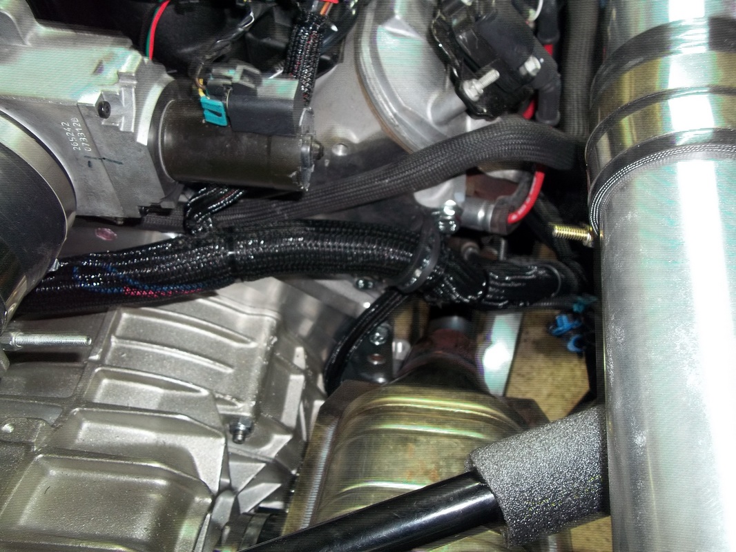
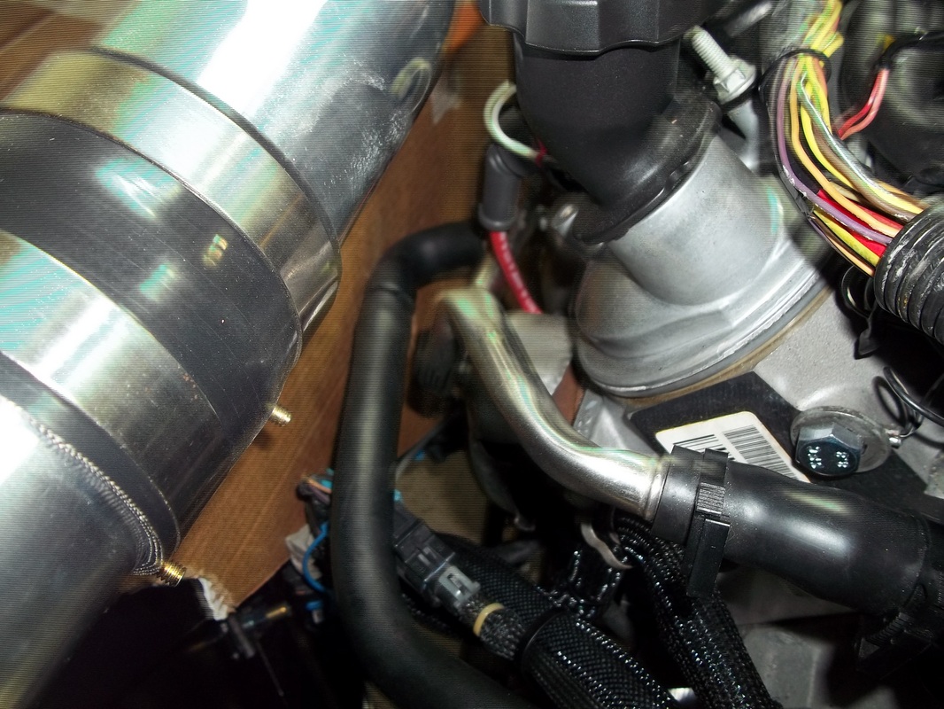
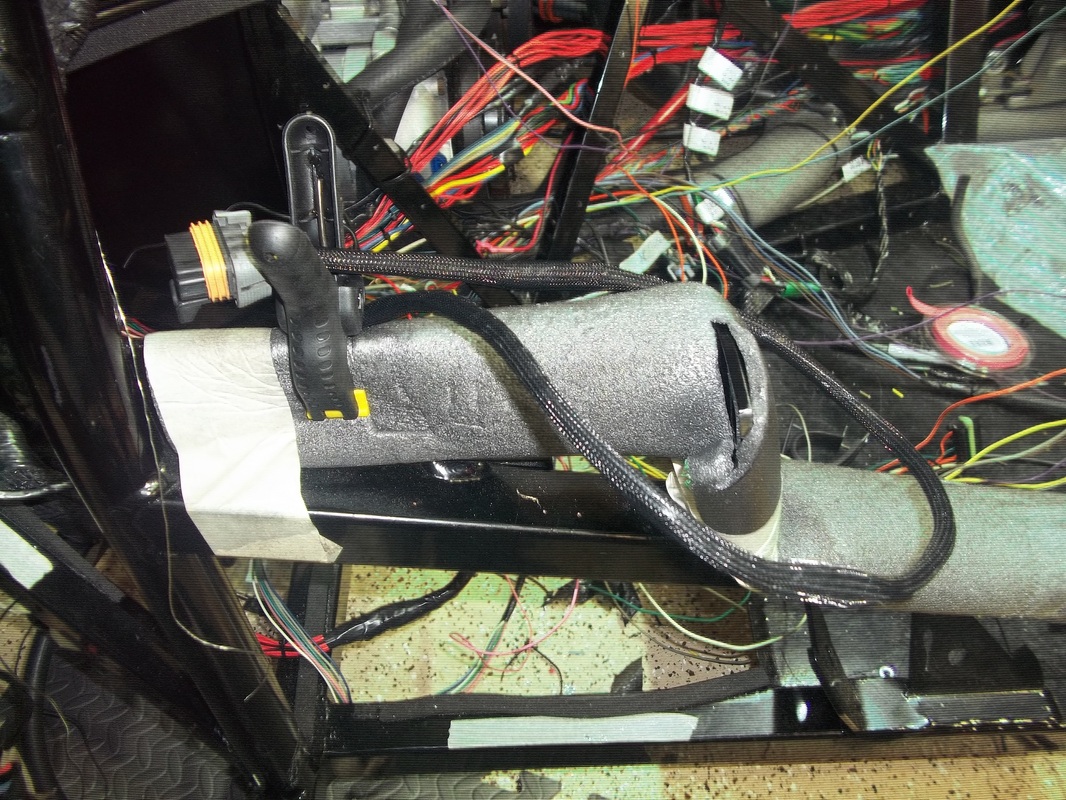
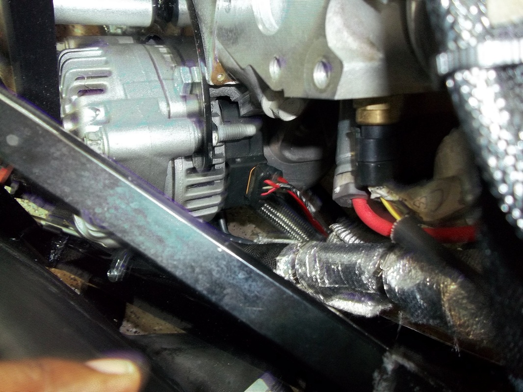
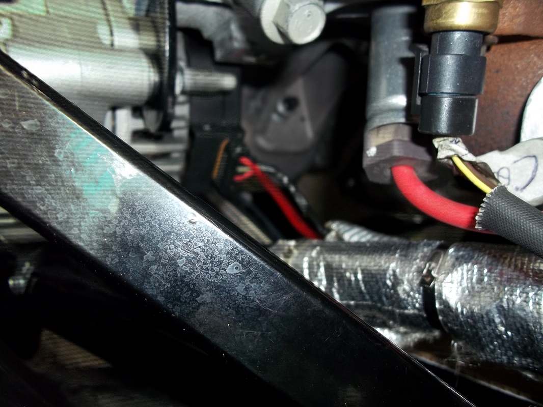
Main Battery Cable
Next I plan to put the car on stands next so that I can complete the engine connections and complete the Main Battery Cable protection and securing. It is an heavy guage cable and is not fused. For extra protection, along with taking every percaution in placement and securing, I am sliding it into a 3/4 heater hose.
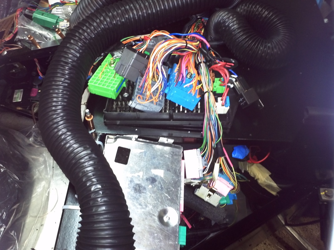
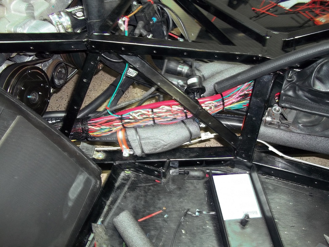
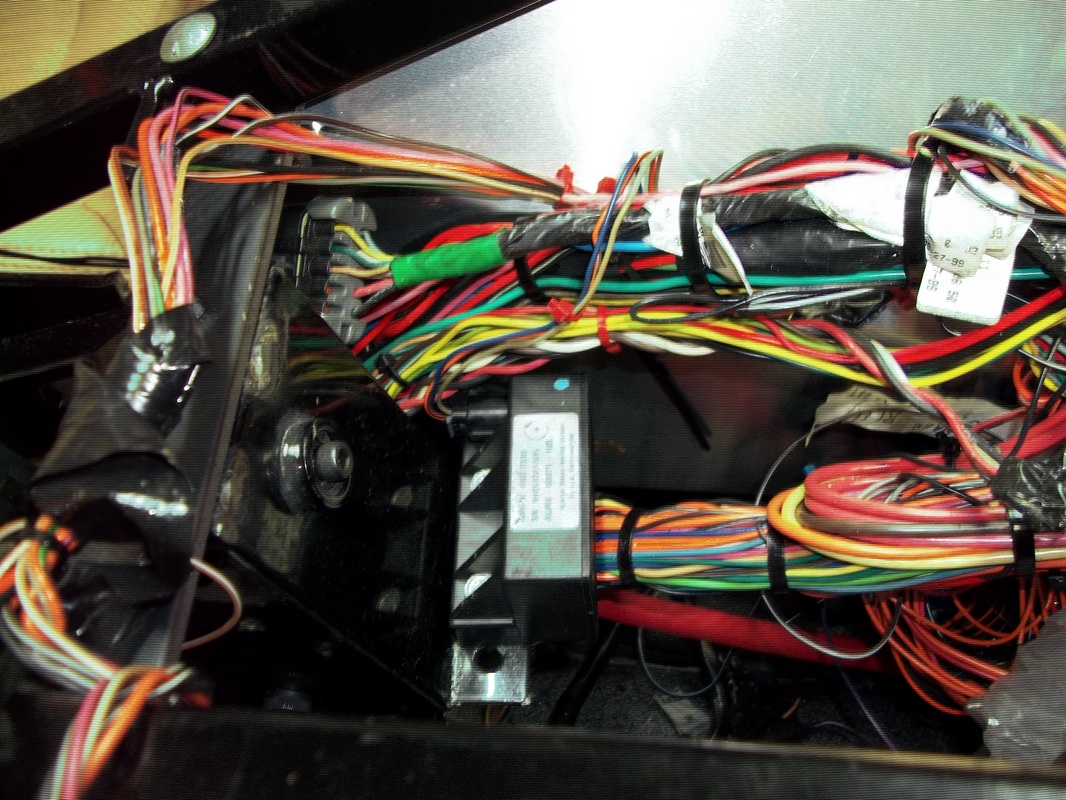
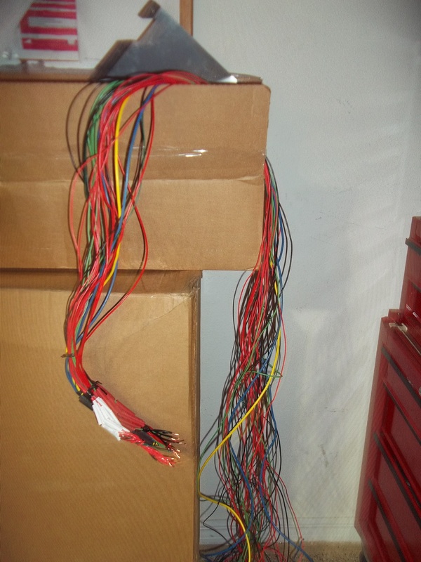
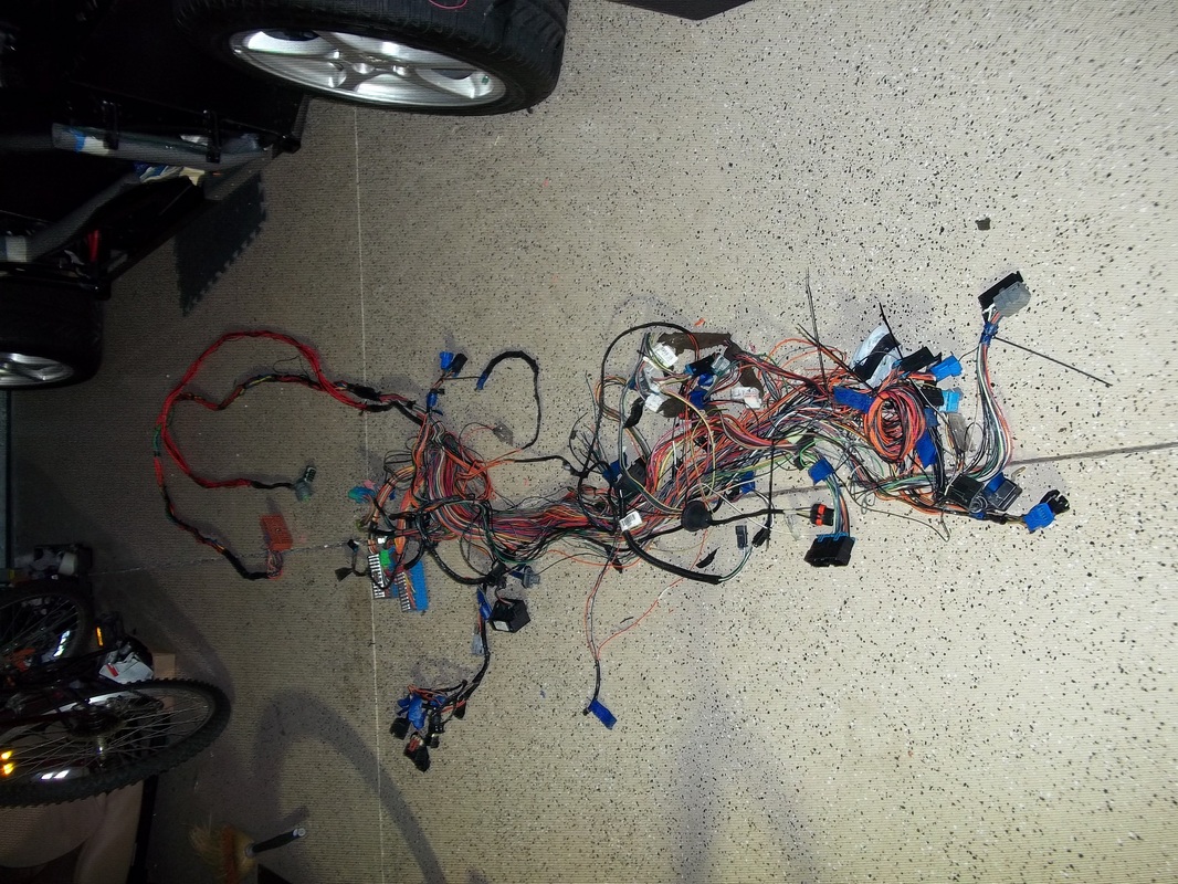
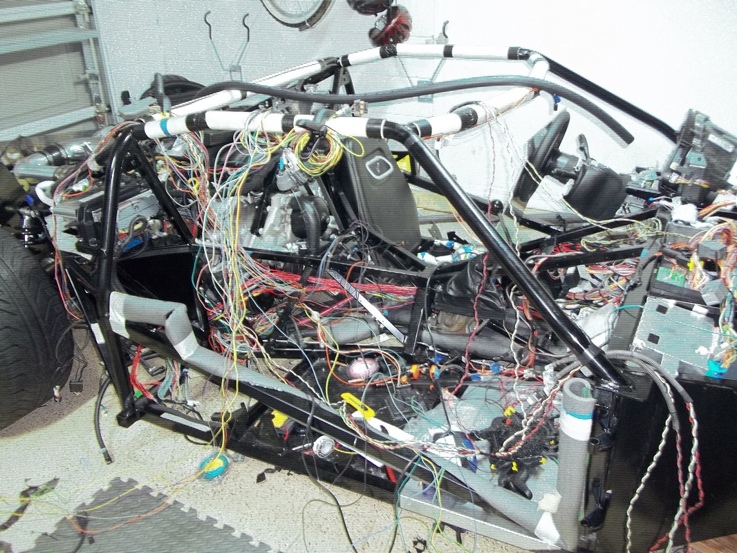
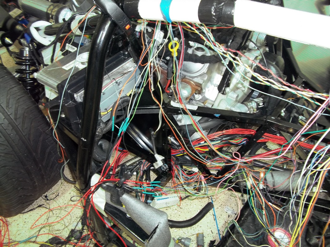
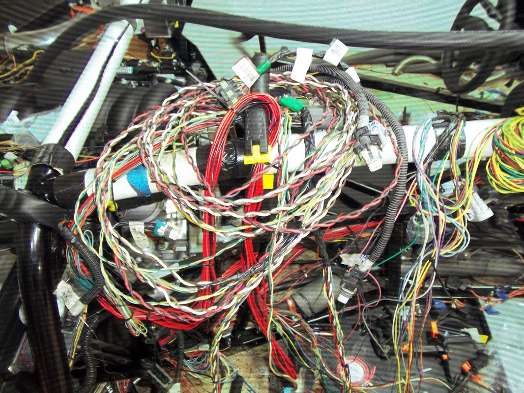
Wiring
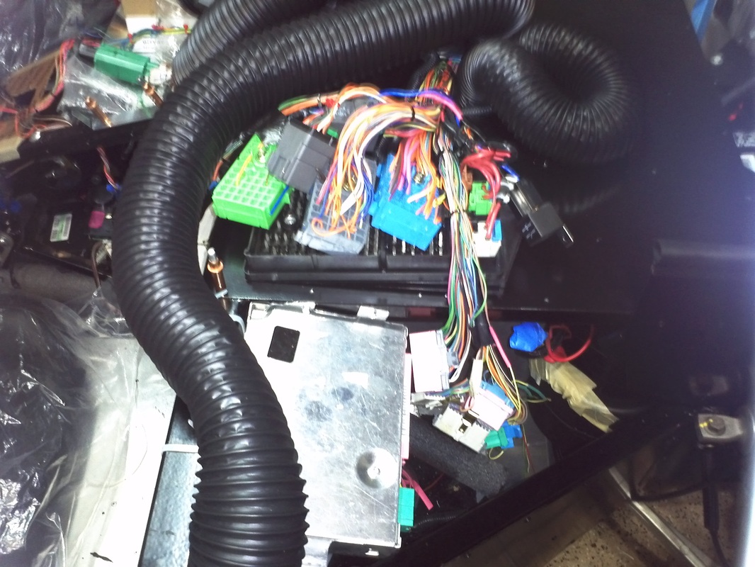
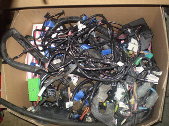
The real madness begins. When I stripped my donor I remove the complete harness intact with every single termination. There is a major positive to doing it this way instead of using the included GM painless kit. There will be minimum actual wiring. Meaning the harness was engineered and completed by GM and I will not have to rework the system making for an ALMOST plug and play install. If every component was in the same place as in the corvette it would be a plug and play. The negatives are finding a location to mount components and having to extend a lot of wires so that the termination reaches its respective terminal.
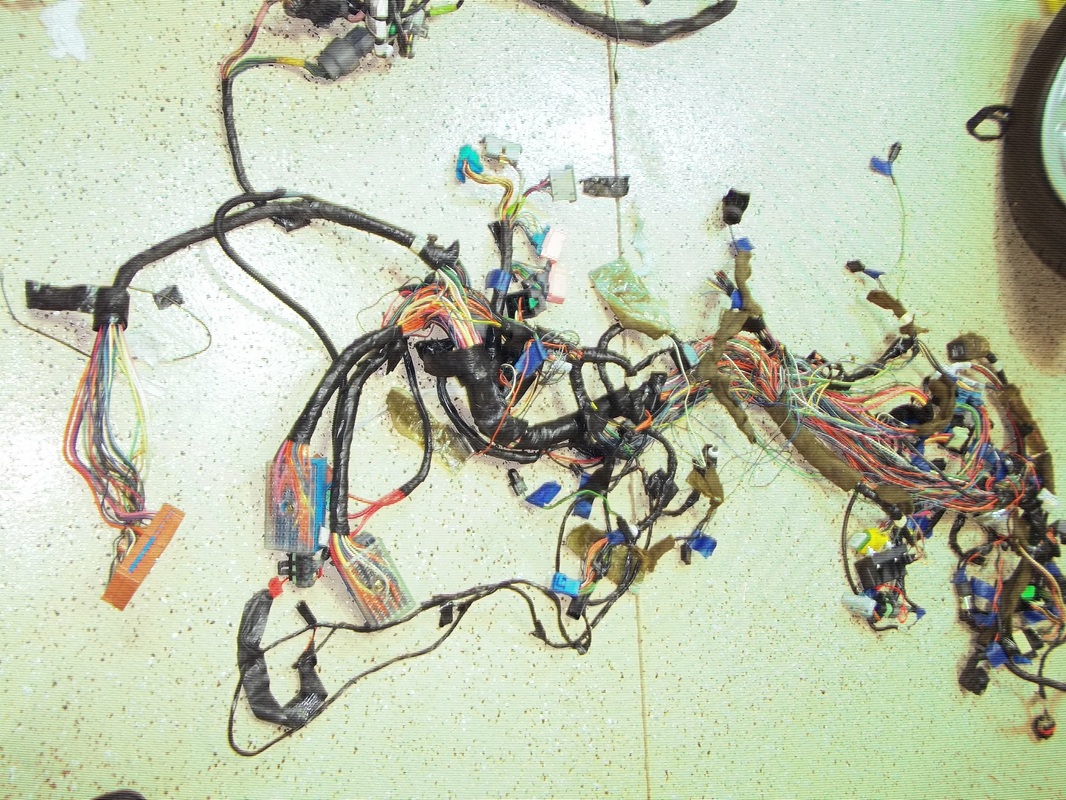
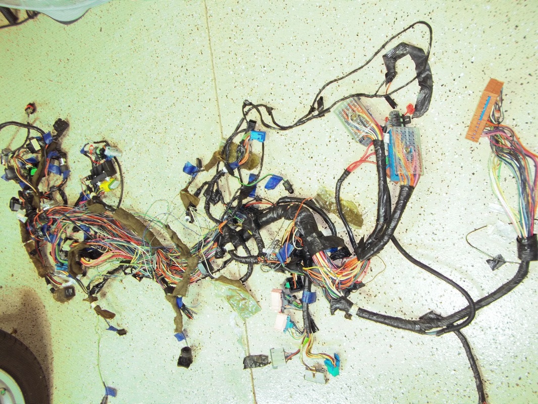
This is the COMPLETE electrical harness from the donor C5 corvette. It is intact and complete with every termination, fuse box and module. I plan to us the harness and incorporate ALL of the functions as they were on my donor. ABS, traction control, Instrument cluster, HUD. Will it happen? Only time will tell. Right now I have two primary concerns; redoing/fitting the instrument cluster and all of the wires I am going to have to extend.
This is the COMPLETE electrical harness from the donor C5 corvette. It is intact and complete with every termination, fuse box and module. I plan to us the harness and incorporate ALL of the functions as they were on my donor. ABS, traction control, Instrument cluster, HUD. Will it happen? Only time will tell. Right now I have two primary concerns; redoing/fitting the instrument cluster and all of the wires I am going to have to extend.
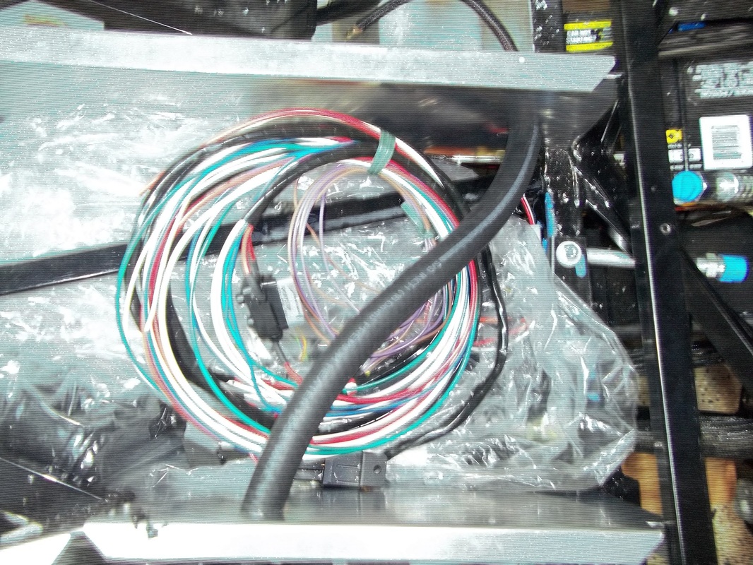
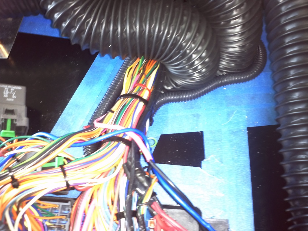
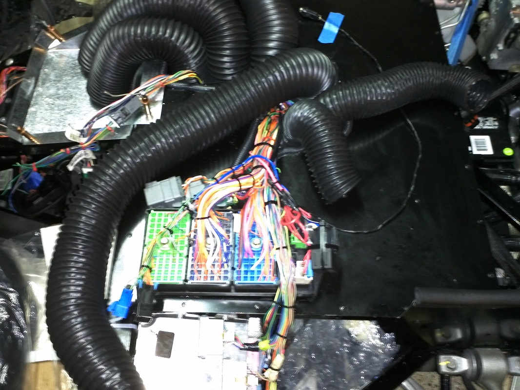
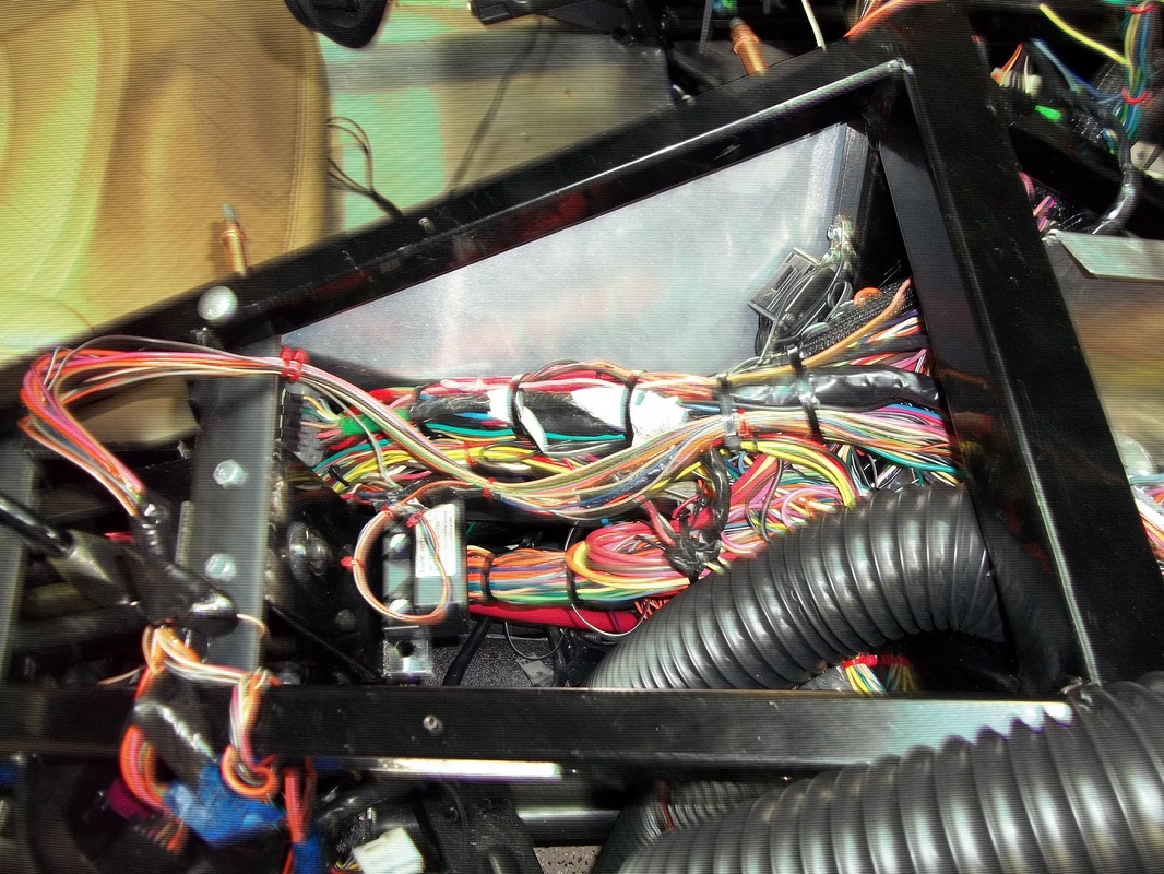
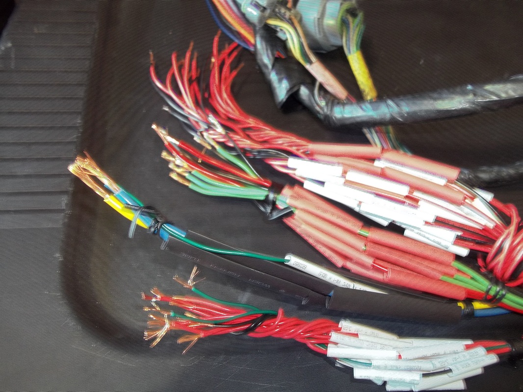
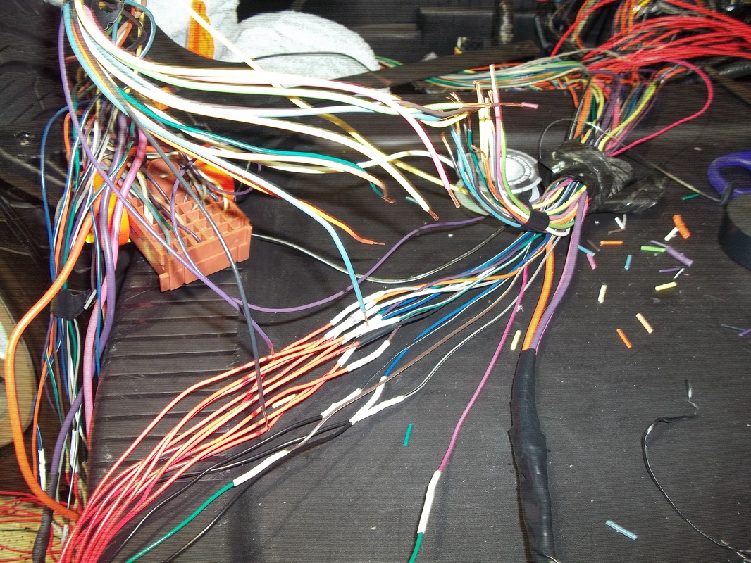
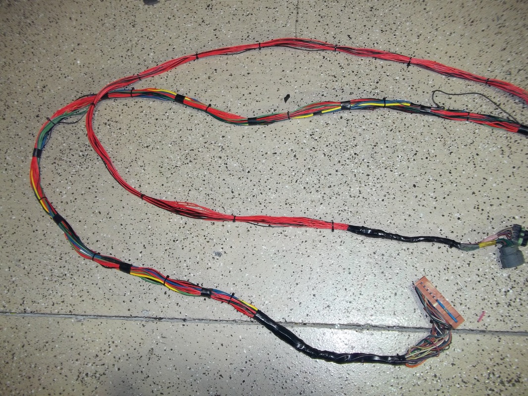
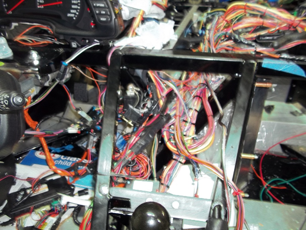
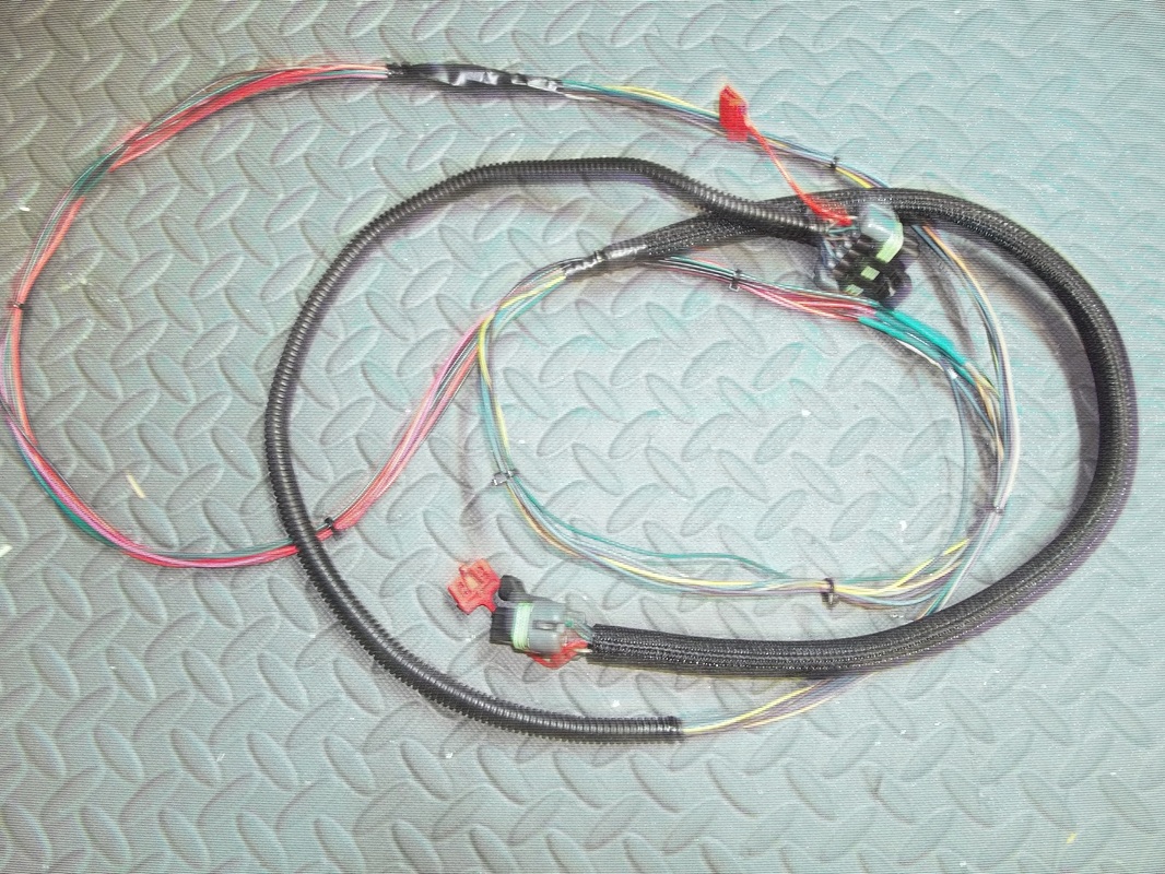
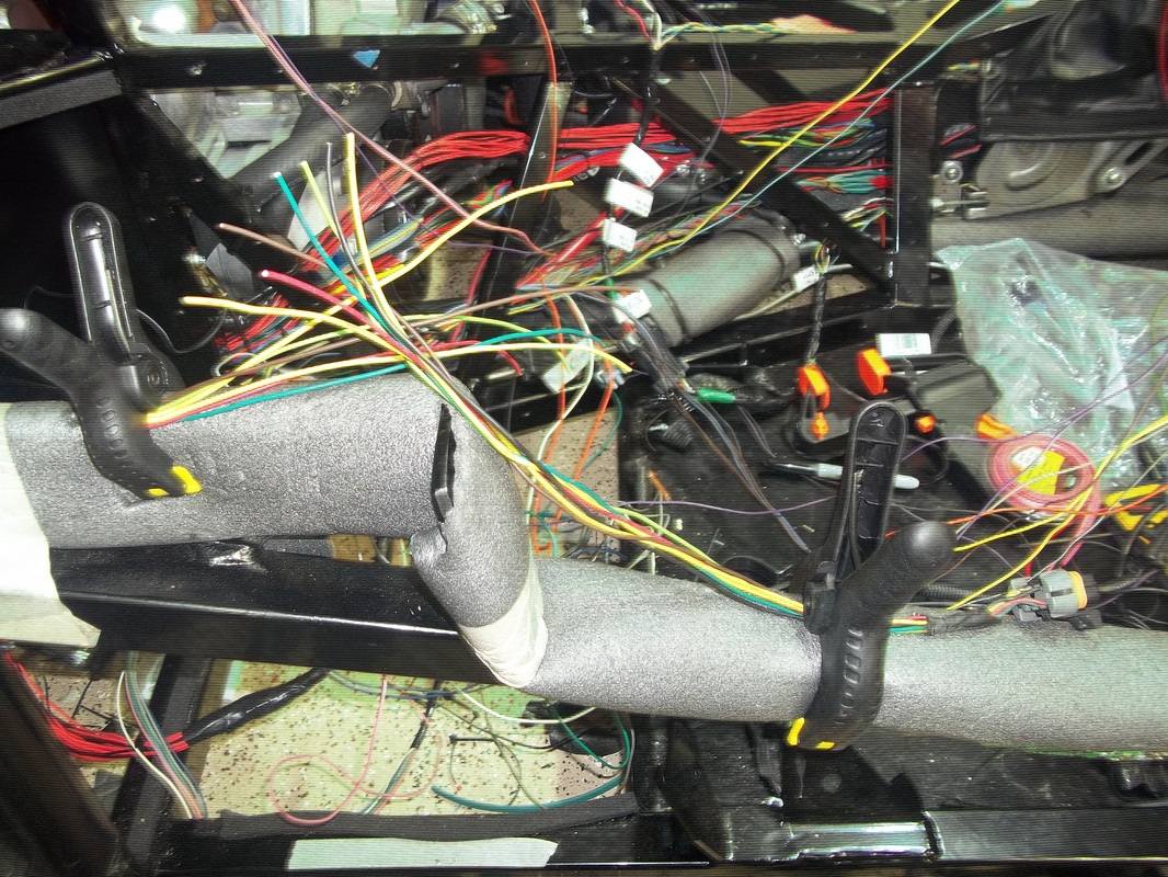
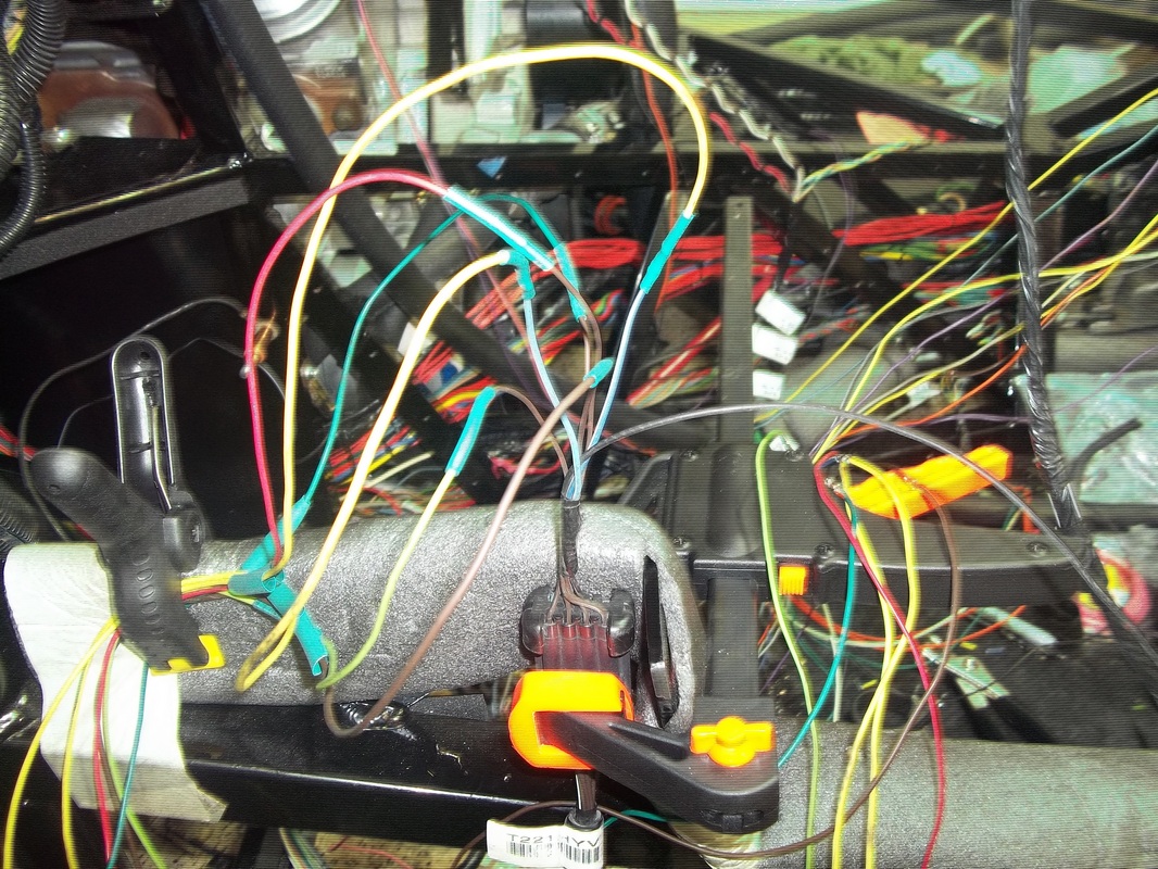
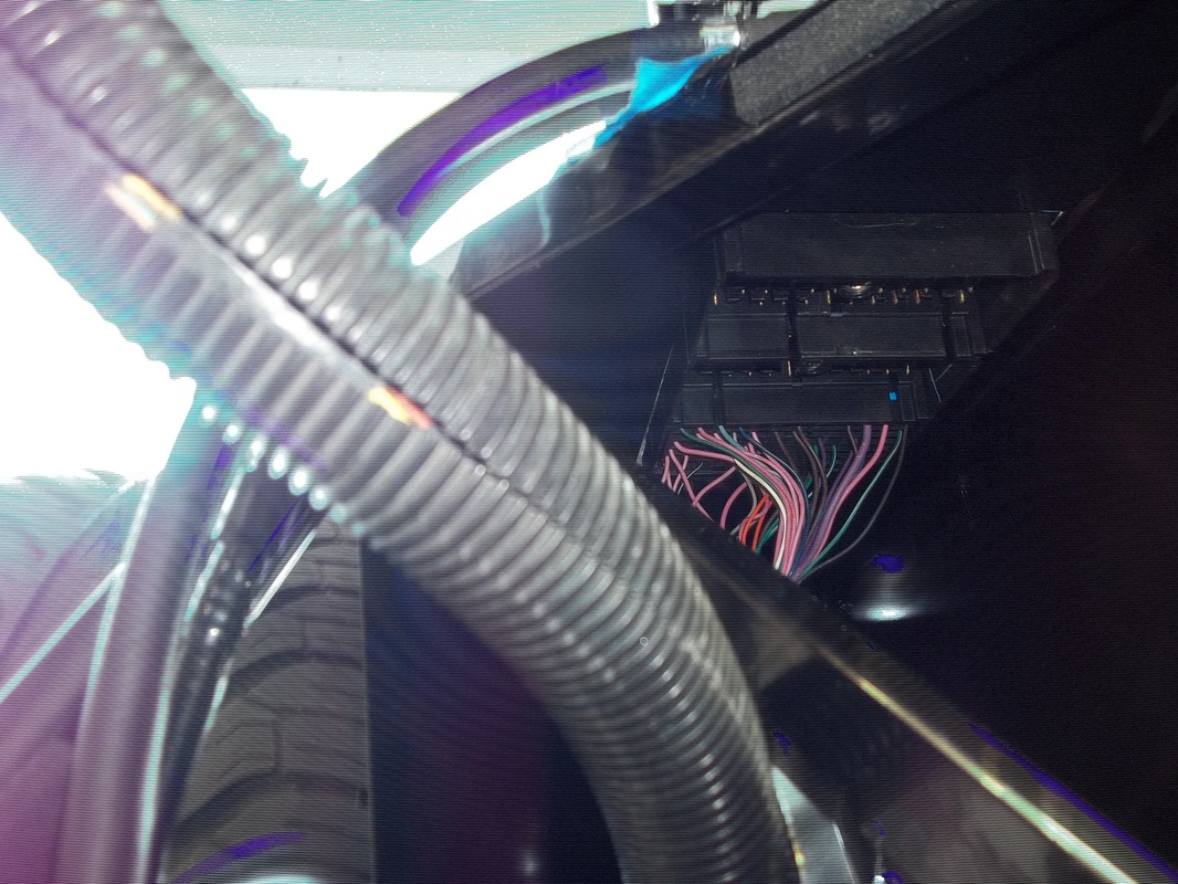
BCM/Ignition Harness Wire Extending. EBCM/Lights/Fuel System Wiring
58 of the wires (yes, FIFTY EIGHT) on the ignition/Body Control Module(BCM) harness need to be extended. I'm adding 7' so that the interior fuse panel and BCM can be mounted under the dash. Each is soldered and covered with heat shrink tubing.

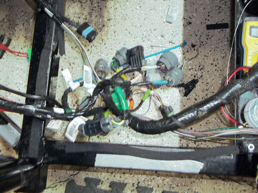
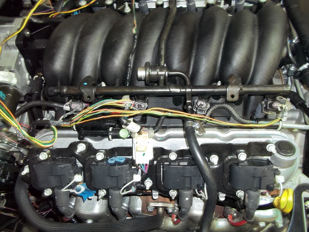
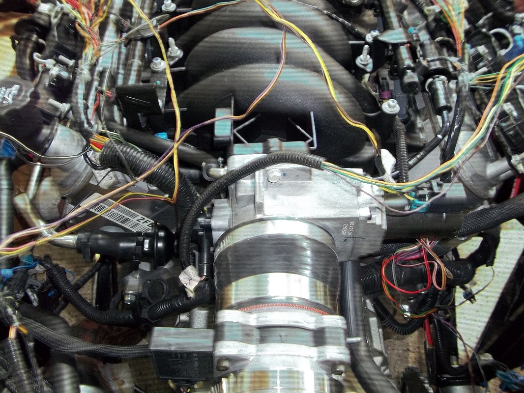
Engine Harness
I removed the engine harness from the under hood fuse box and other harnesses. I connected it to the PCM and lay the remainder over the engine. I removed loom and tape and plugged in as many of the terminals as I could. I will have to extend some wires.


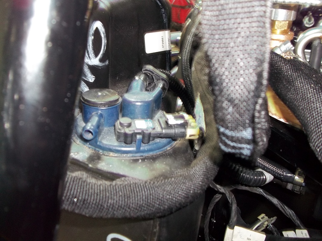
Fuel Tanks and Evap Canister Harness
No modification was required for this harness. I plugged it in and ran it along side the cross over line.

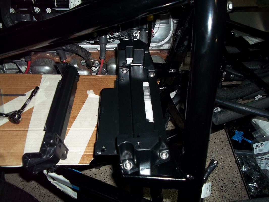
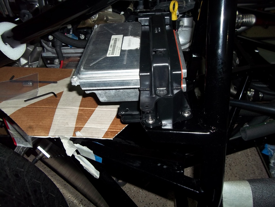
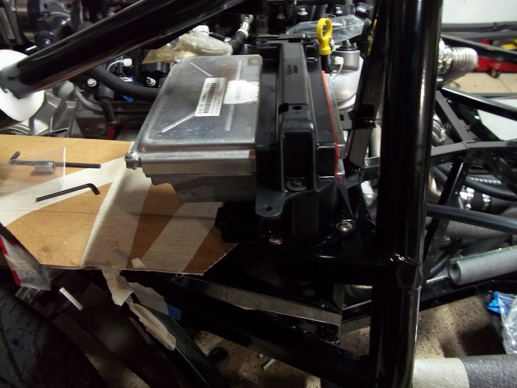
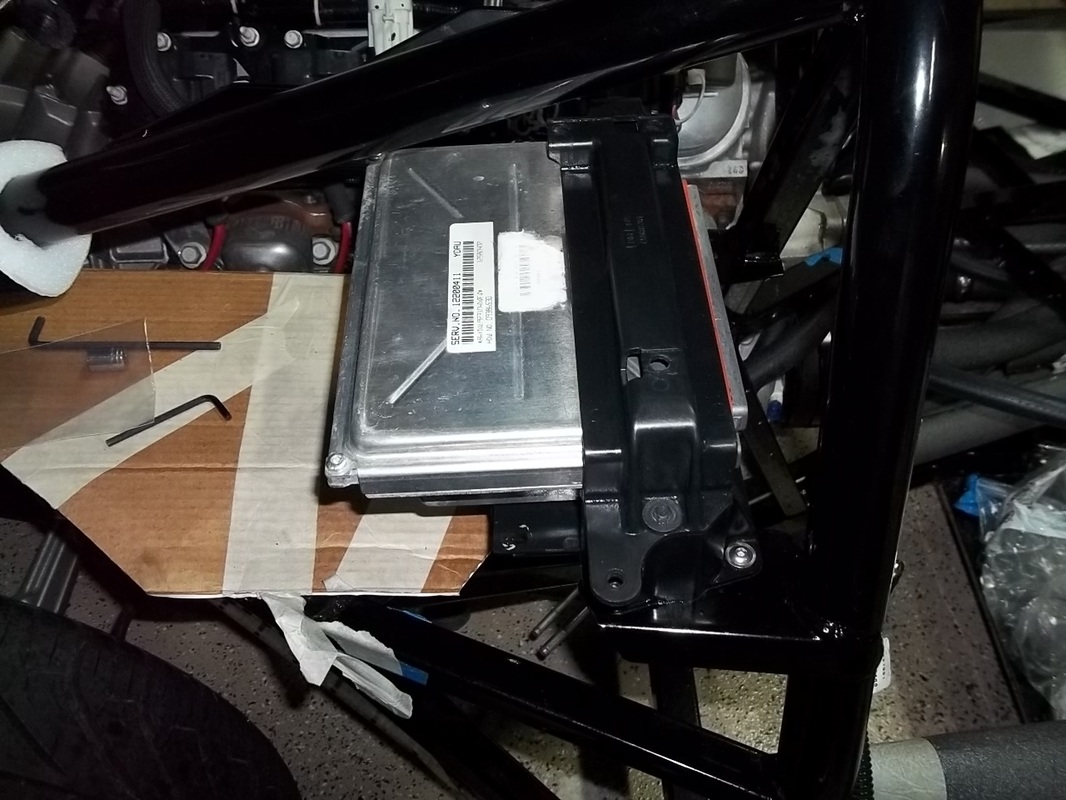
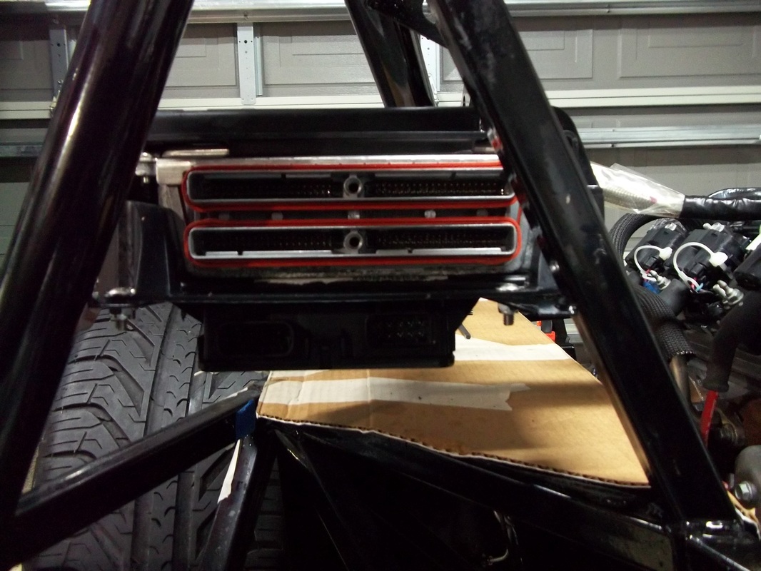
Computer Bracket Mount-Throttle control-ModuleComputer PCM
I had to purchase the lower portion as my donor mount was cracked. Just trimmed the tabs flush and mounted the TAC.


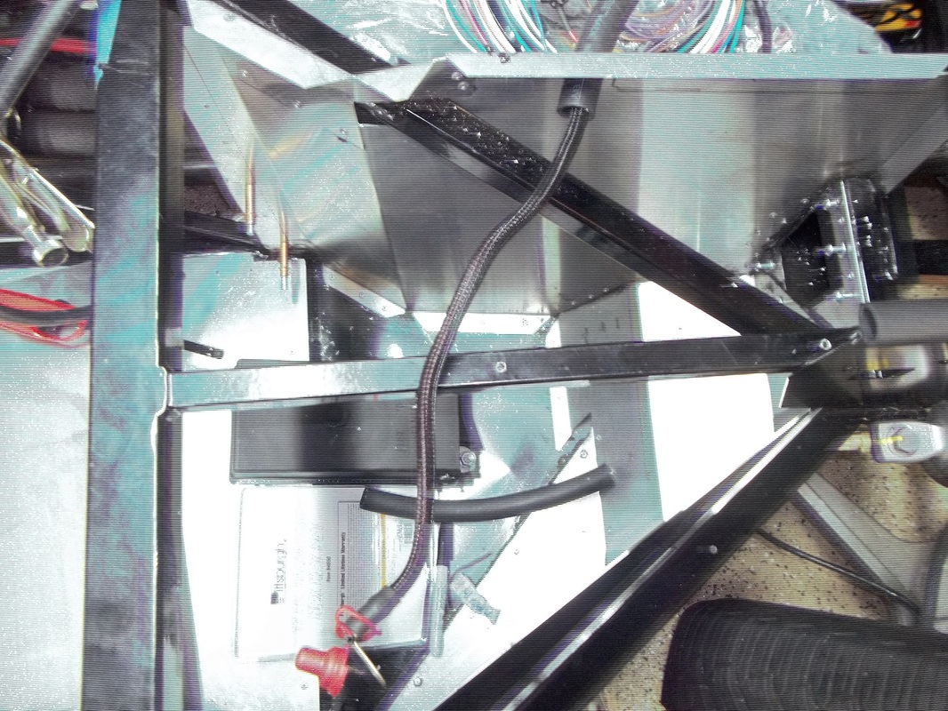
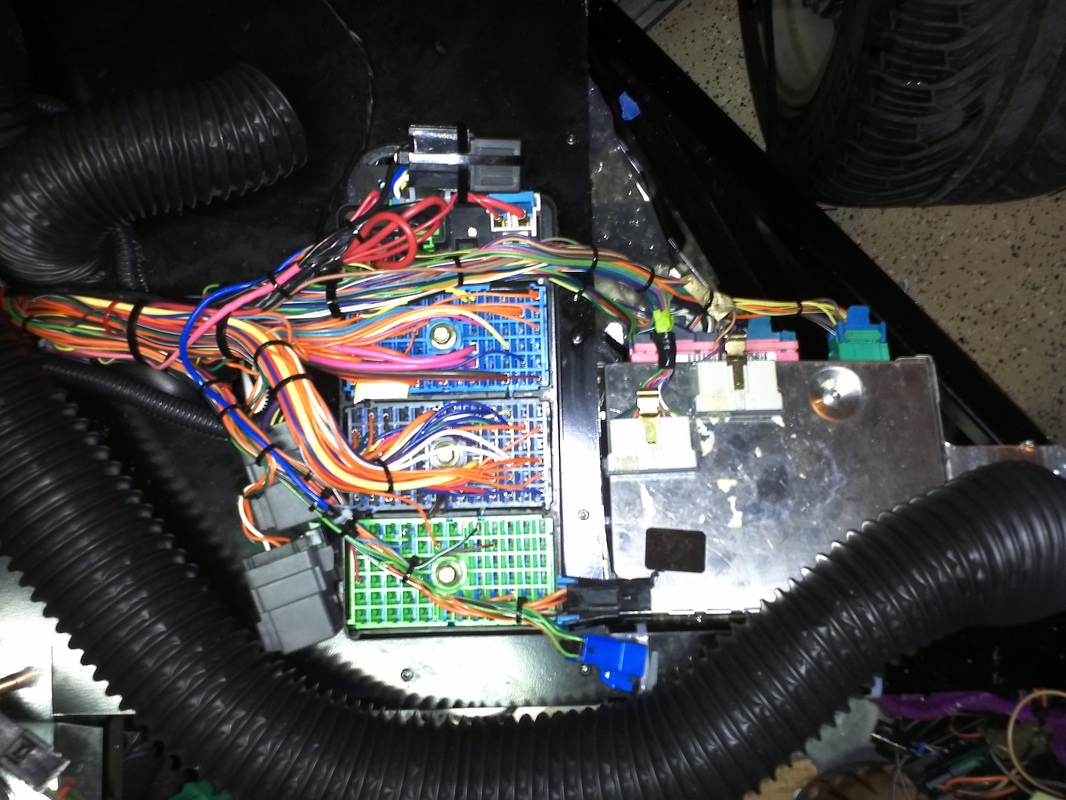
Power, Main & Distribution Circuit
Battery power for the IP fuse panel was run through the aluminum over the HVAC. I ran it through a 5/8 heater hose. This provides protection and keeps the interior isolated. Since the main-power is a long run I ran it through some 3/4 heater hose in the section under the compressor into the engine bay. Over kill I know, but better safe than sorry. I connect the main-power and the starter cable to the fuse panel. I also mounted the Body Control Module (BCM)