Polyester Spray Filler/Primer Spray and Block Sand
|
|
 |

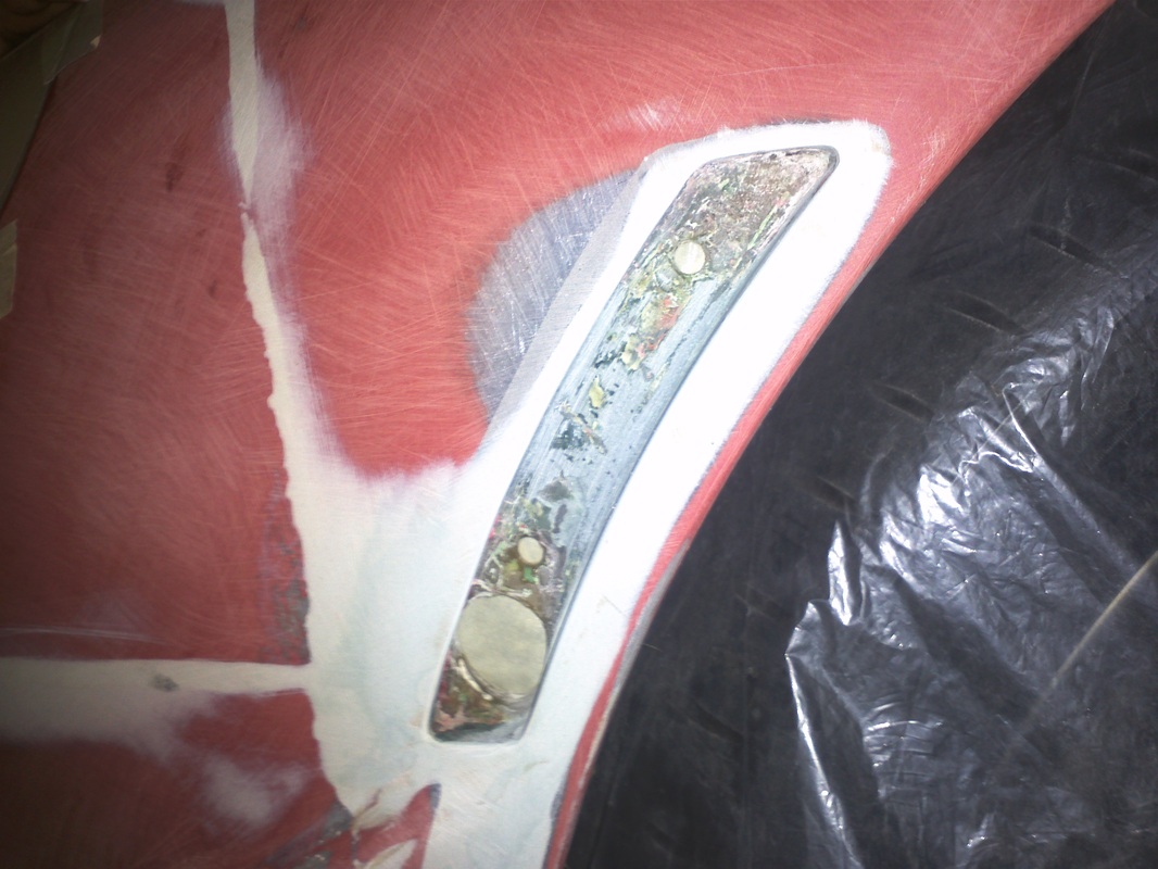
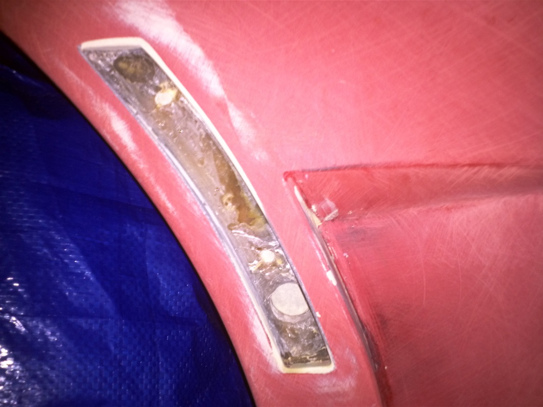
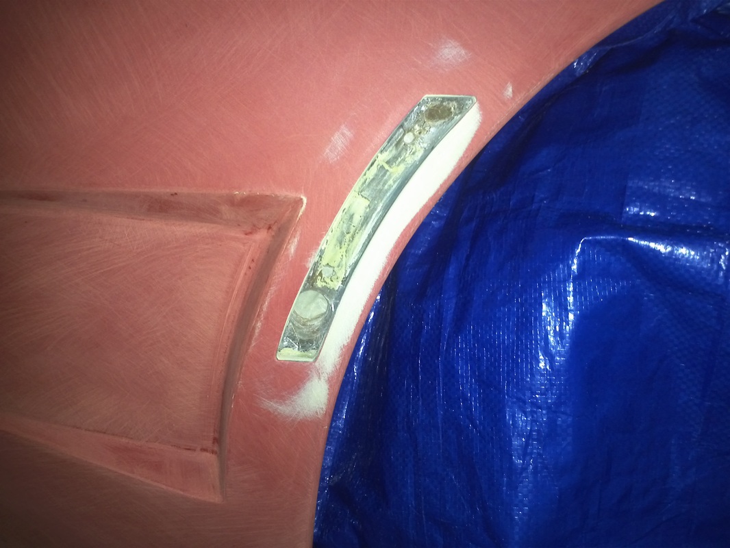
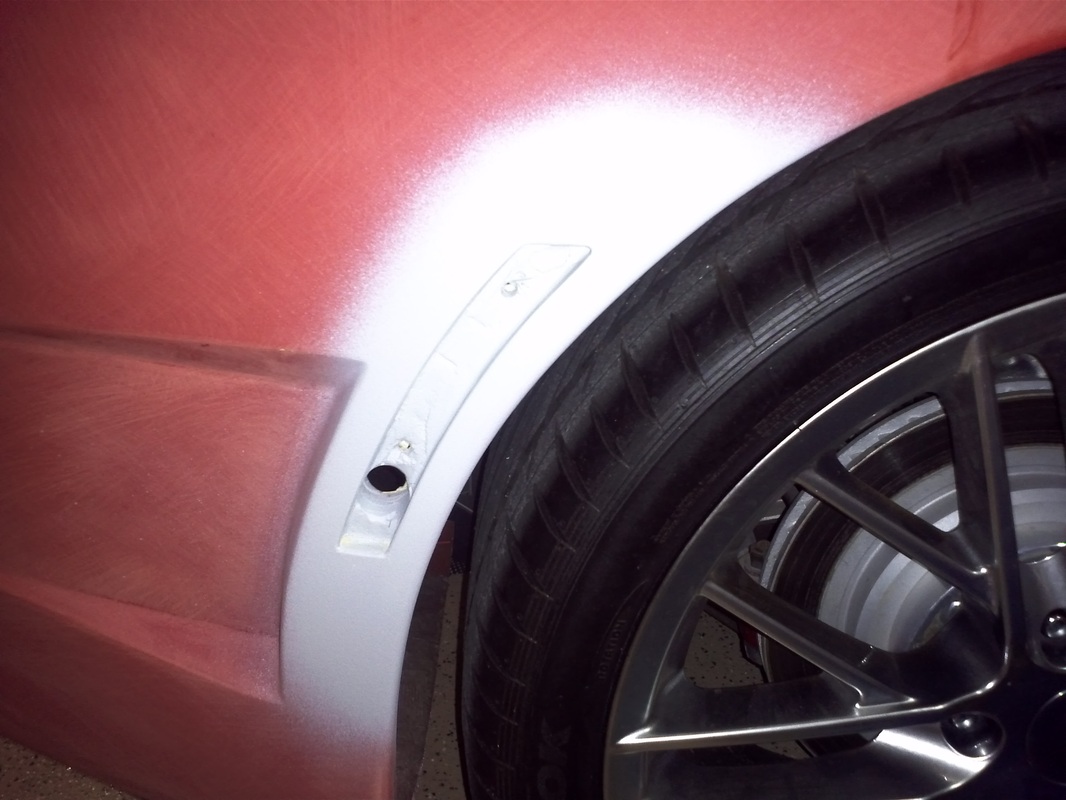
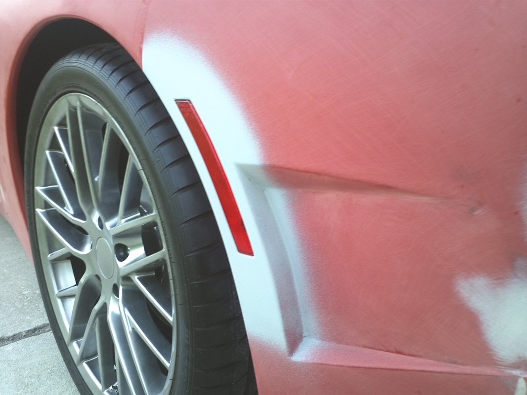
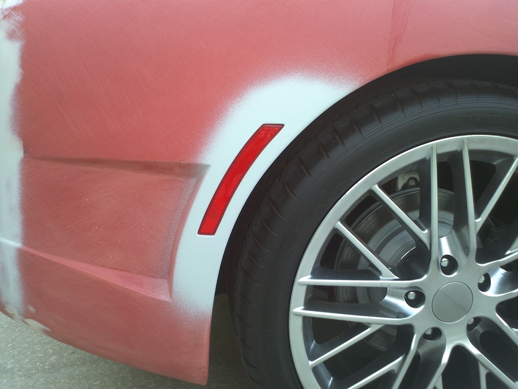
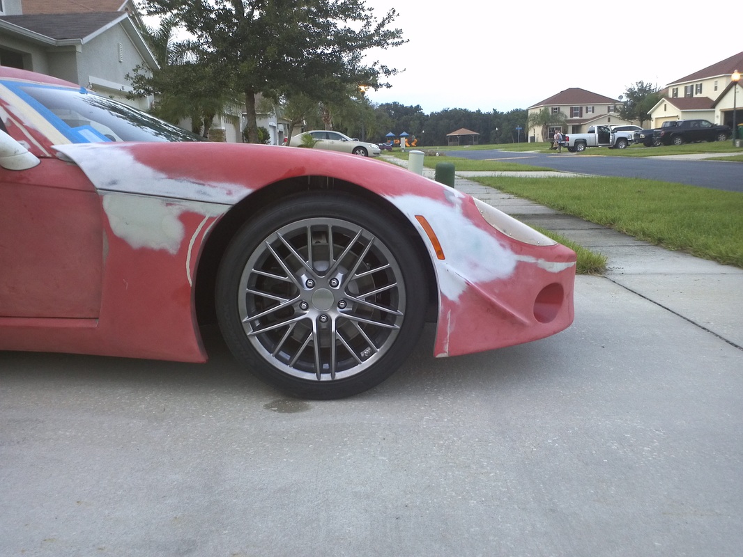
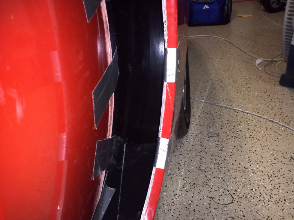
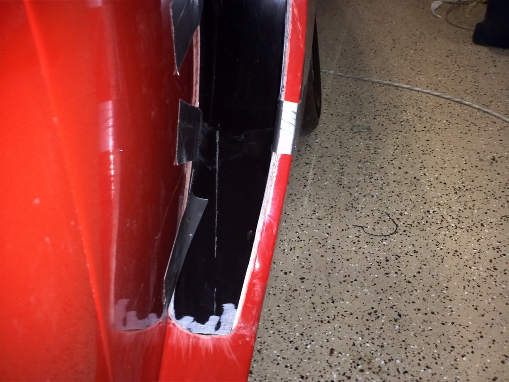
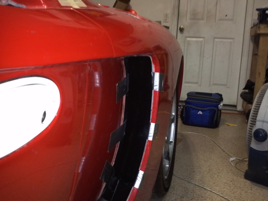
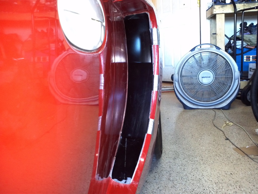
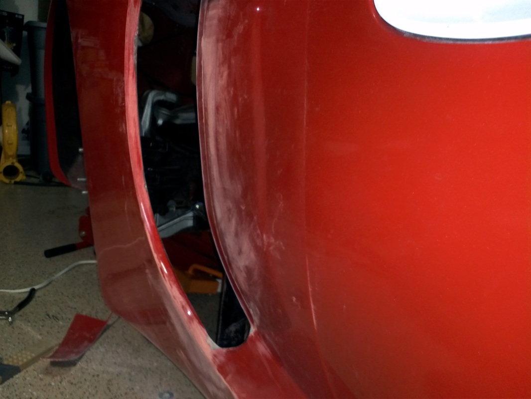
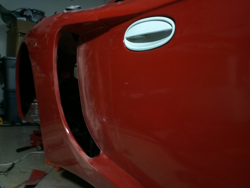
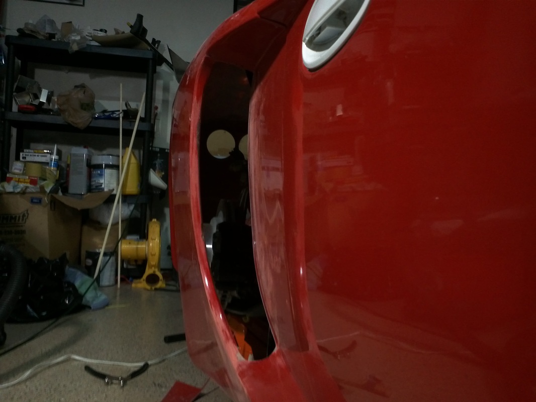
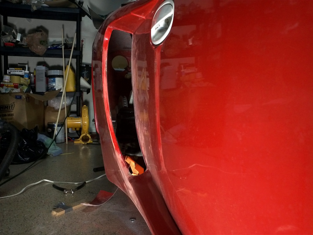
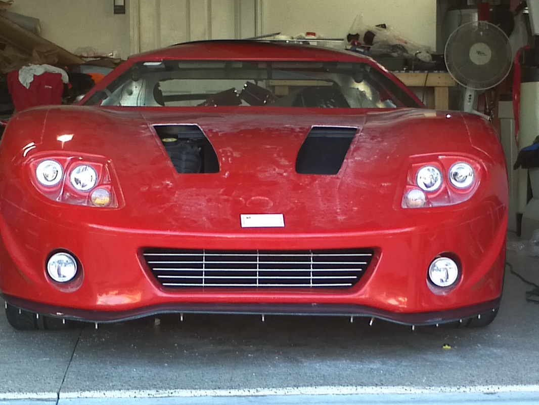
Side Markers
I have been searching for the right markers since prior to starting the build. In my opinion, the addition of markers, in a stock looking configuration, really give the kit a more "production car" look and feel. All of the markers I've seen installed and almost all of them in existence, for that matter, have a general rectangular or oval shape. There have been some builds where markers were added. In my opinion the markers definitely assist in adding to the production auto look and feel.
I credit finding these markers to Kens80v of the SL-C forum. He is building an incredible SL-C. Here is a link to his build thread: http://www.gt40s.com/forum/slc-clubhouse/38446-kens-slc-build-thread.html . His SL-C requires markers to be legal and he chose markers from the Mini. After seeing he was installing them I decided to purchase a front and rear set. Thanks Ken.
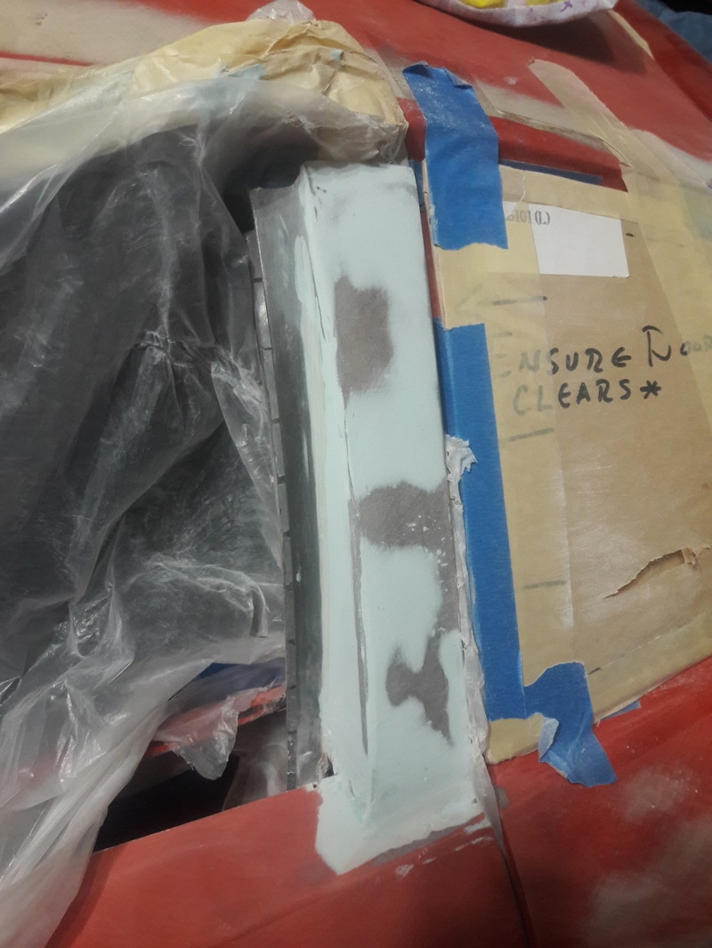
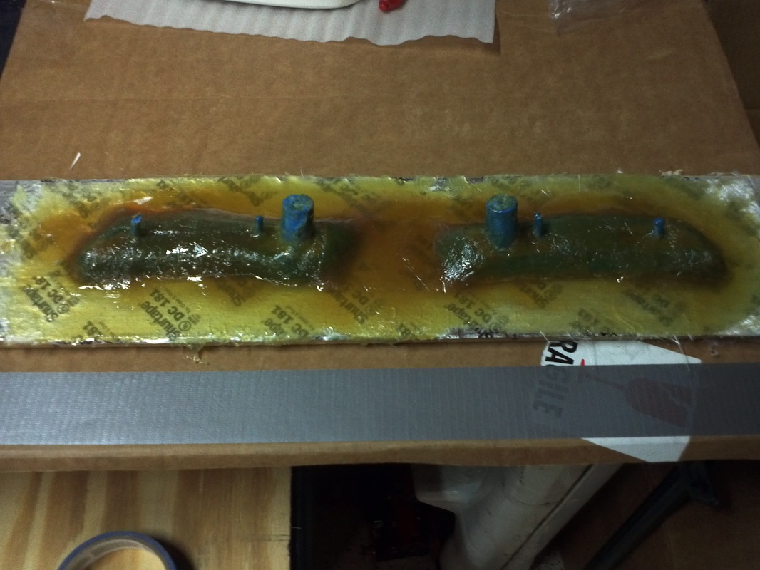
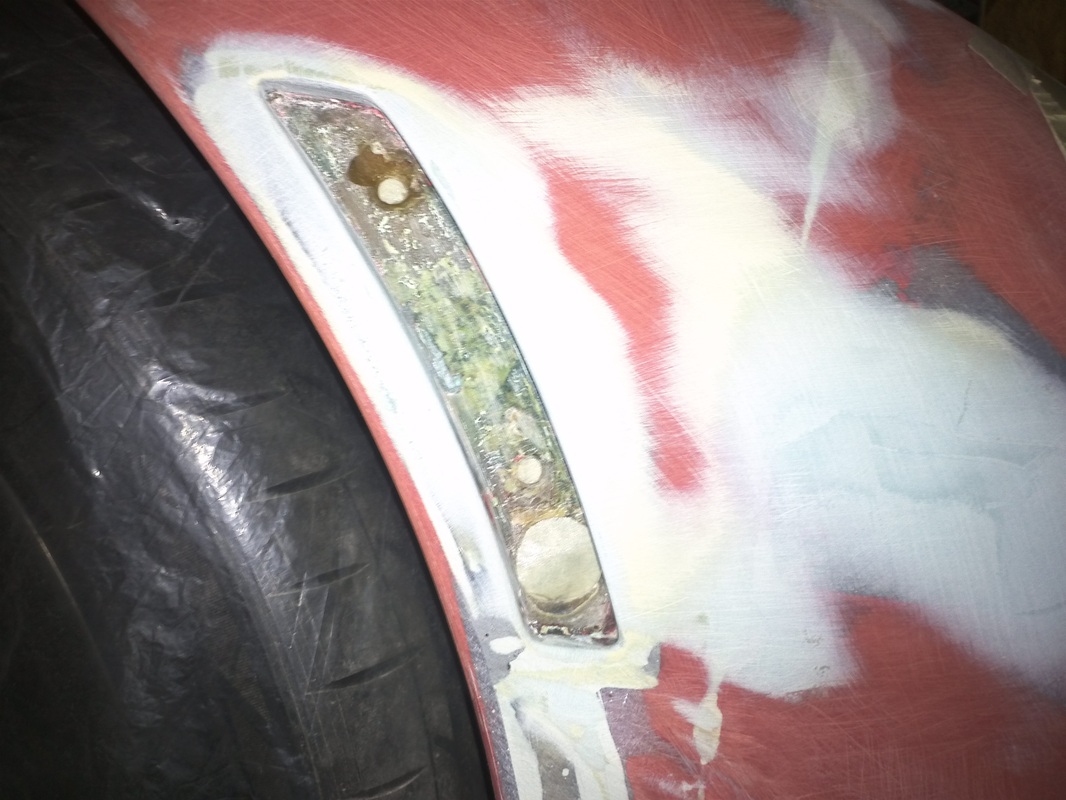
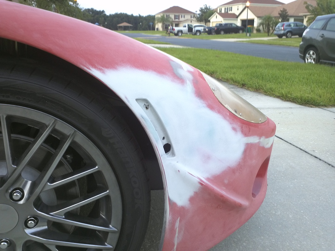
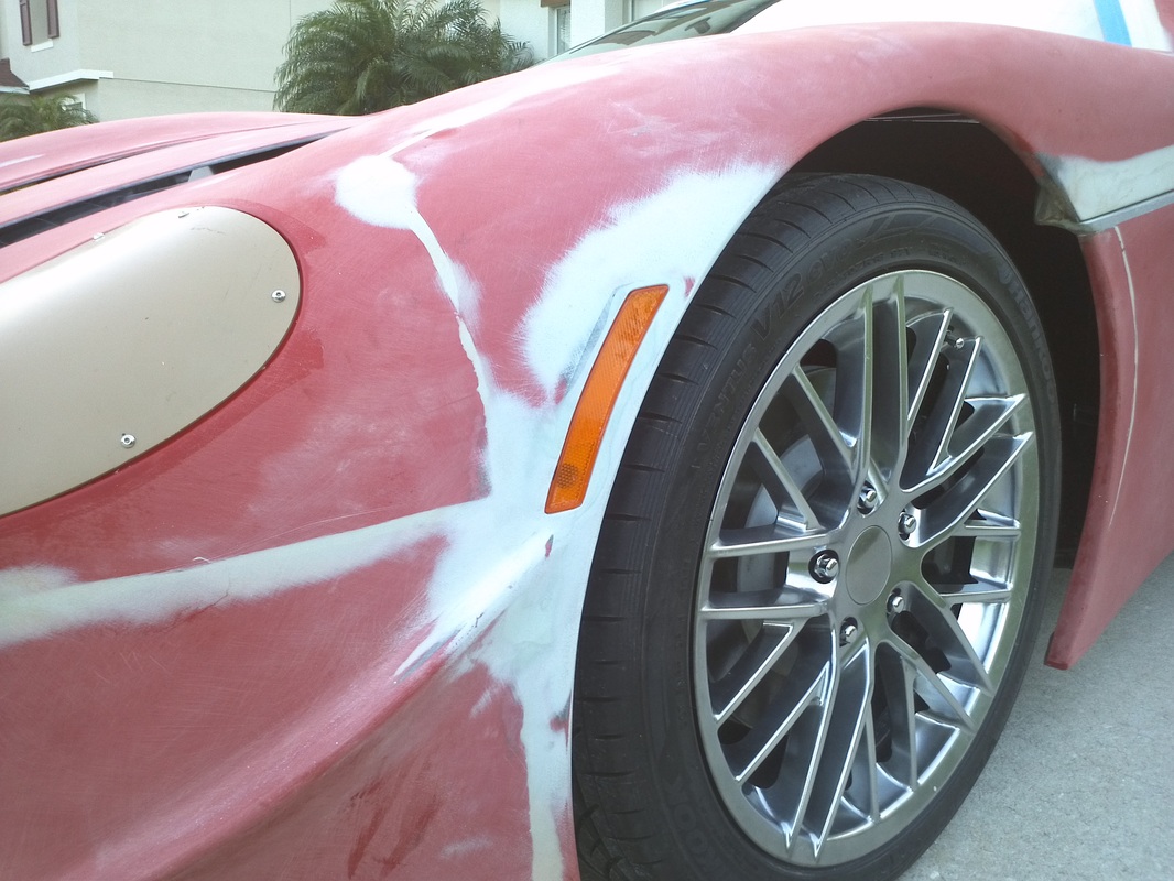
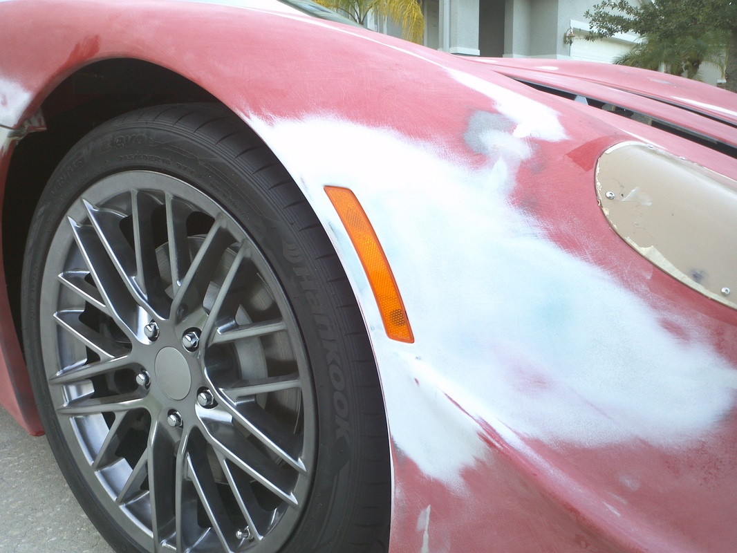
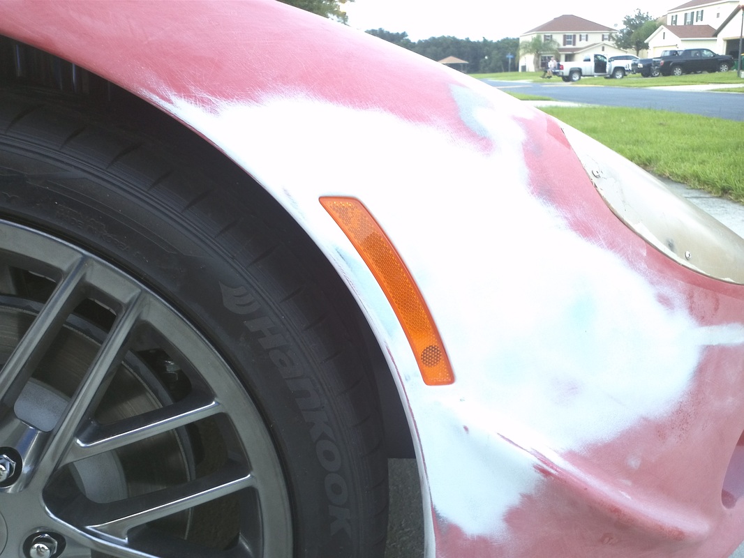
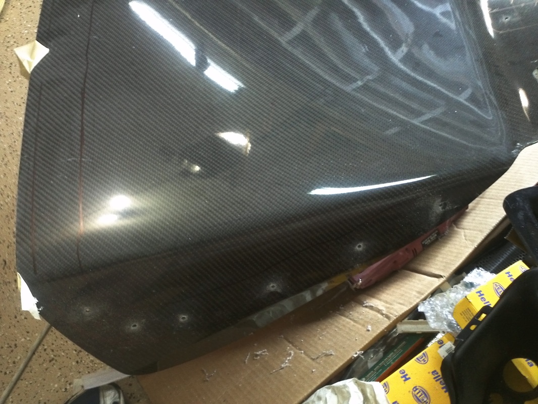
To get a factory like install I created fg pods to house the markers. I then measured and cut the marker openings in the GTM body and trimmed the pods until I got the fit I wanted. I then bonded them in with 3m8115. Because the hood is under some tension I added three layers of 8oz mat to the back side of the front markers to add extra strength.
I credit finding these markers to Kens80v of the SL-C forum. He is building an incredible SL-C. Here is a link to his build thread: http://www.gt40s.com/forum/slc-clubhouse/38446-kens-slc-build-thread.html . His SL-C requires markers to be legal and he chose markers from the Mini. After seeing he was installing them I decided to purchase a front and rear set. Thanks Ken.
To get a factory like install I created fg pods to house the markers. I then measured and cut the marker openings in the GTM body and trimmed the pods until I got the fit I wanted. I then bonded them in with 3m8115. Because the hood is under some tension I added three layers of 8oz mat to the back side of the front markers to add extra strength.
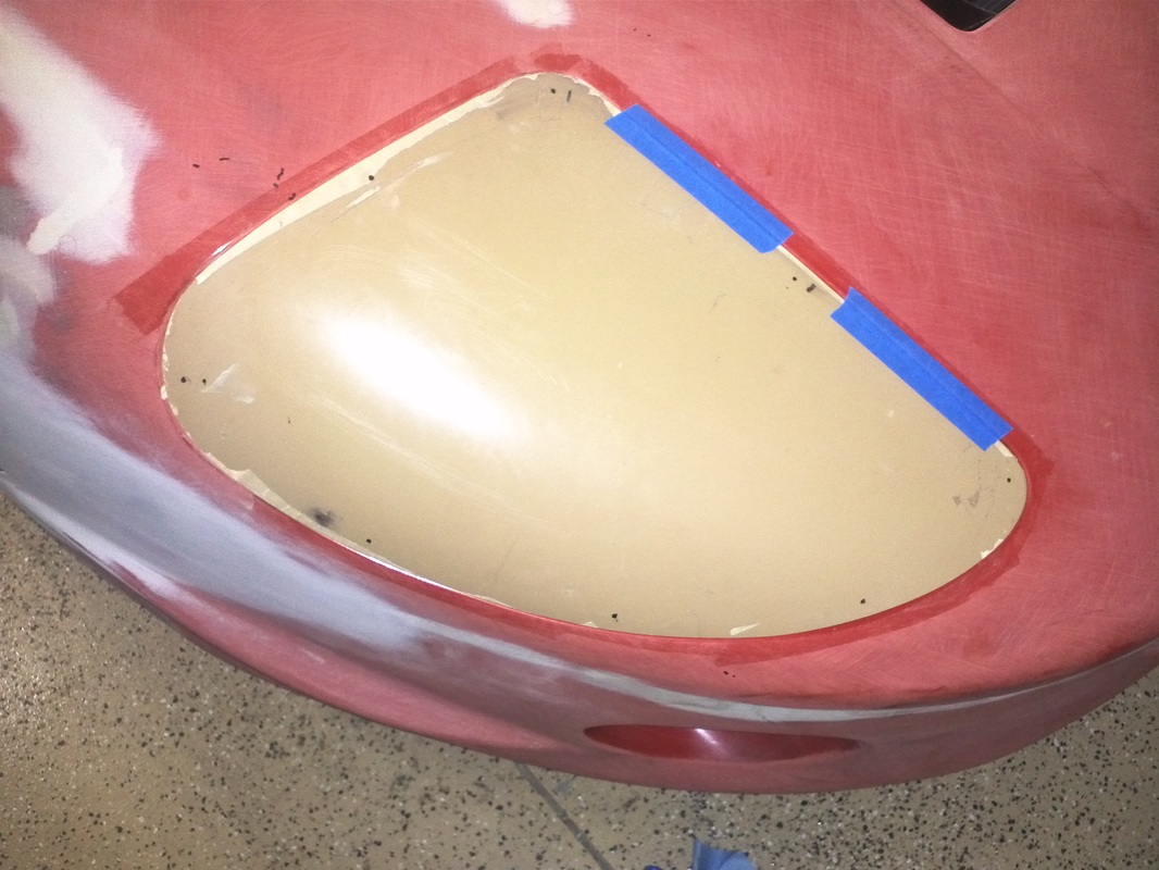
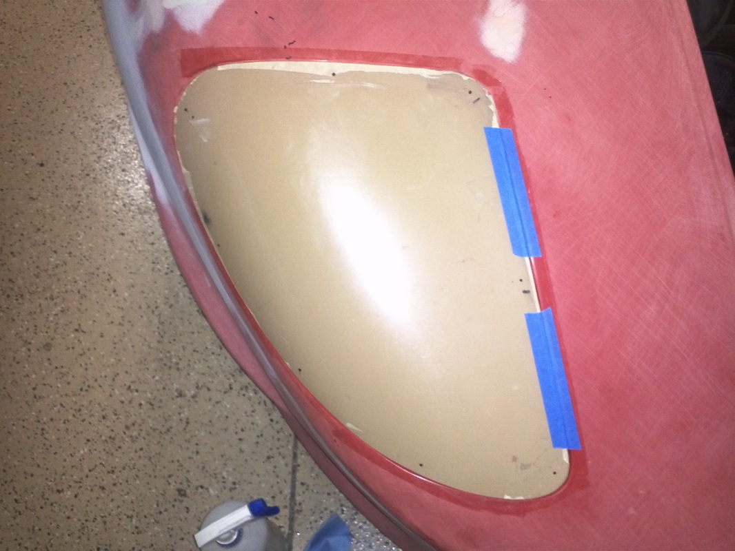
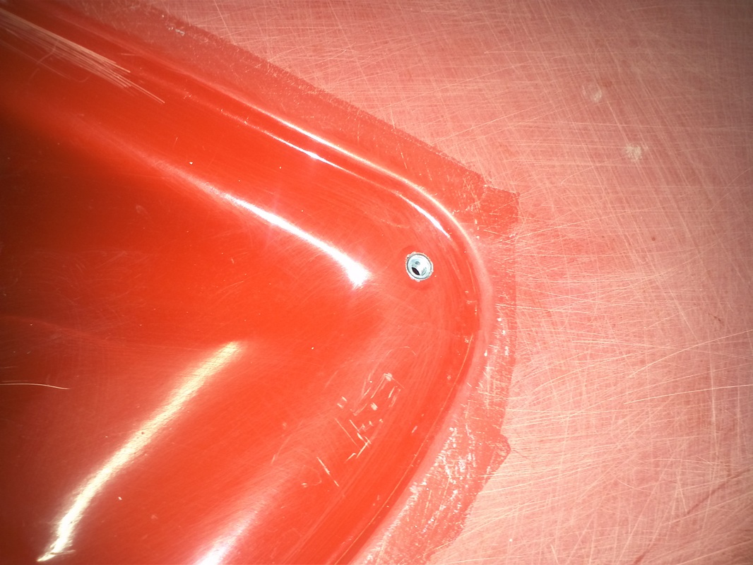
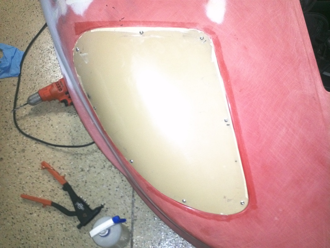
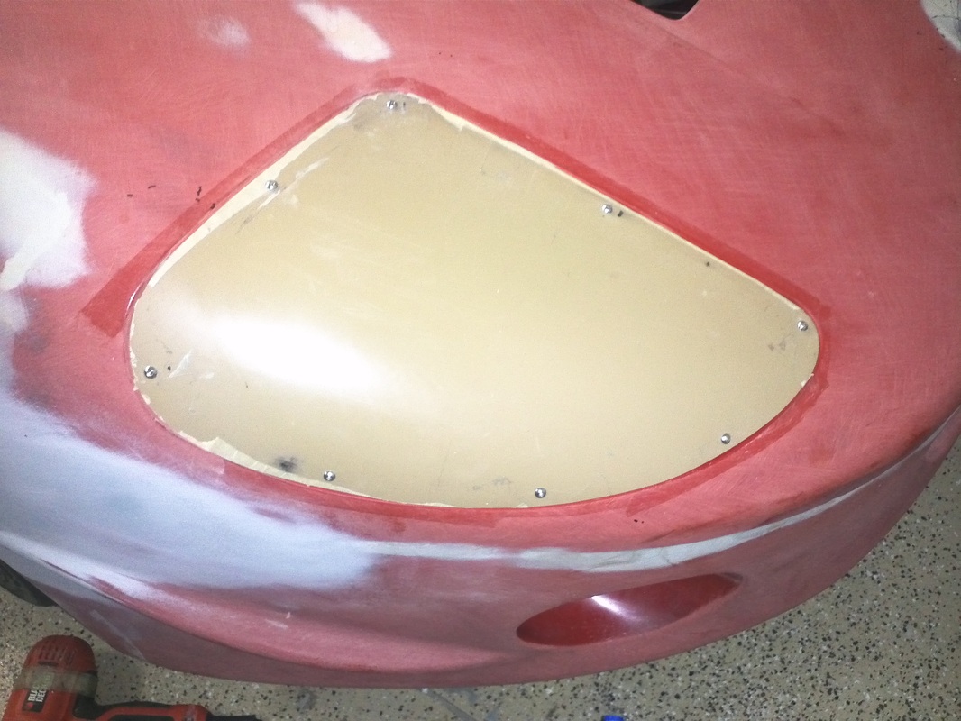
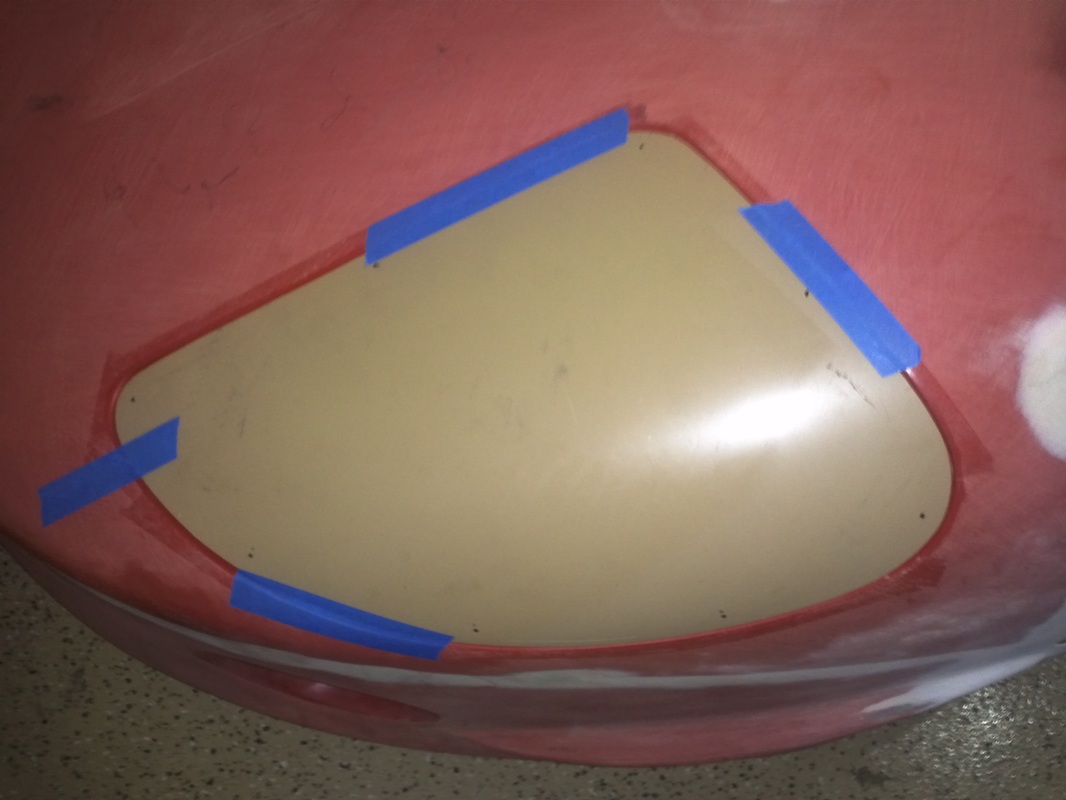
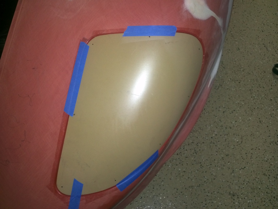
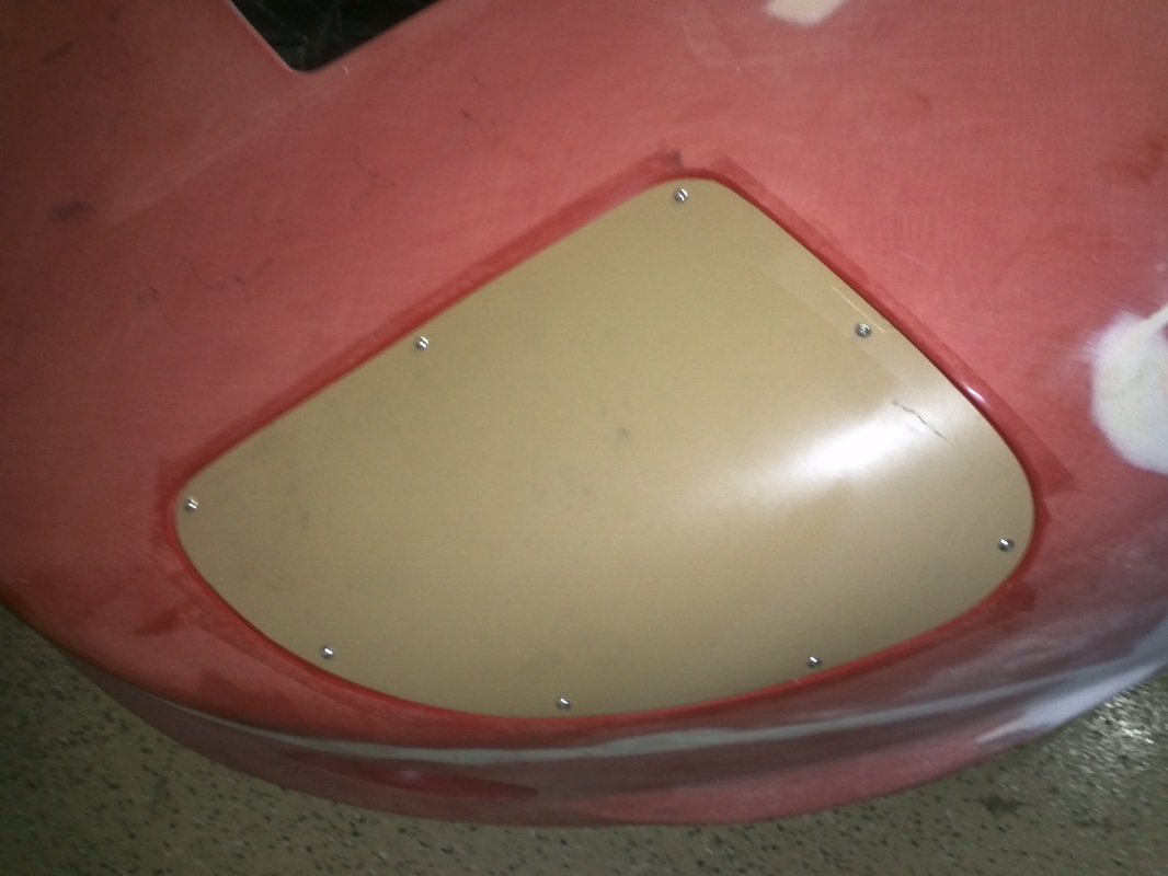
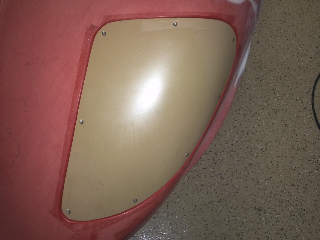
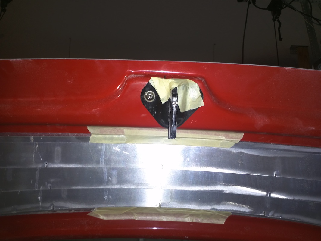
Headlight Cover Mounting
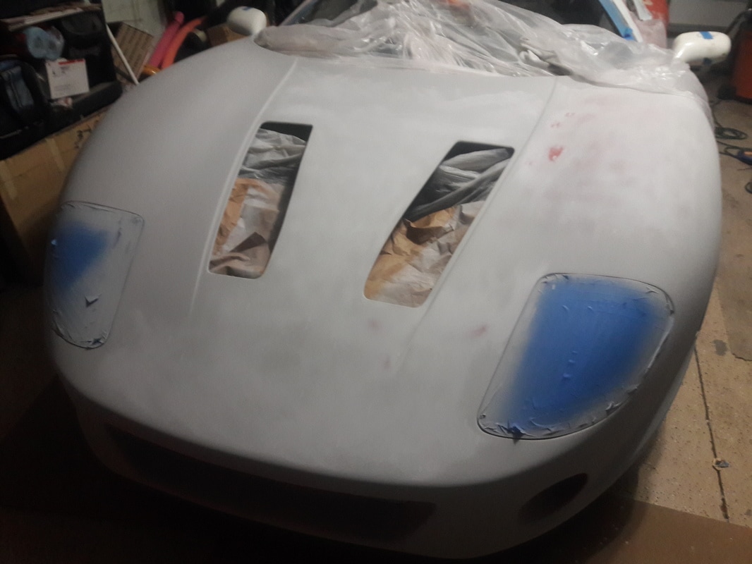
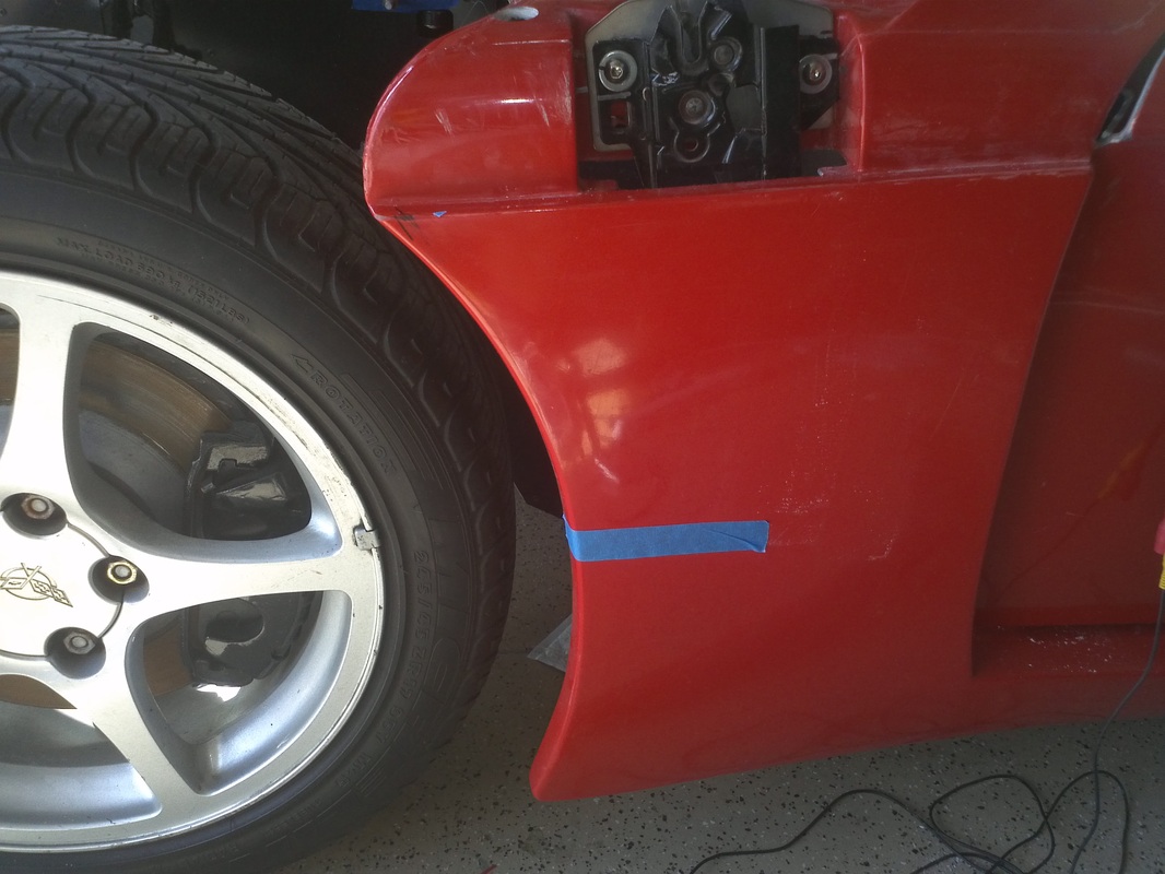
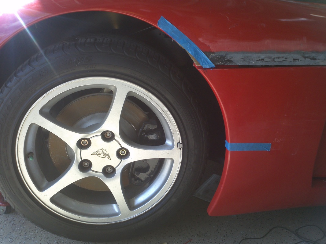
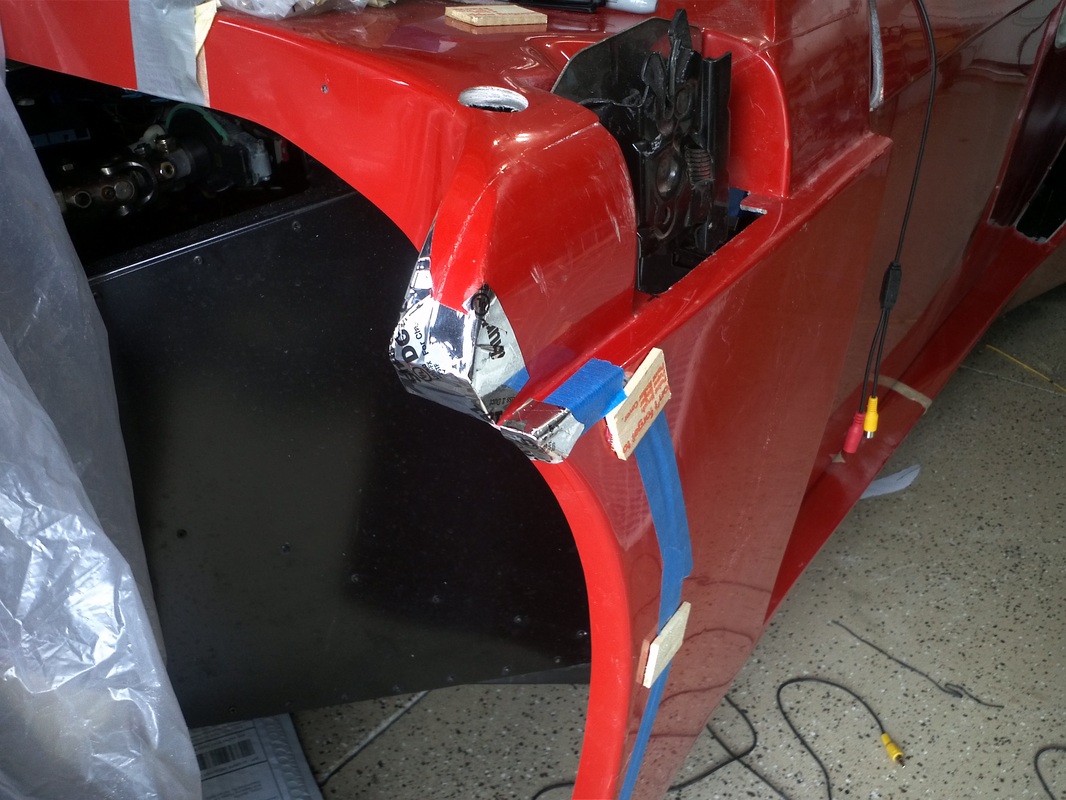
I originally wanted to bond the covers to the housing. I really prefer the clean look, but because I do not want to lose full access I decided to bolt them on. Michael (Rumrunner) used 8-32 Rivet Nut Inserts and Button Head Socket Cap Screws, with great results, so I decided to go the same route. I changed the rivet nut insert tool for 8-32 inserts. The inserts require a 1/4" hole. I pulled the white tape, that had been holding the covers on, and used the blue tape to hold the covers while I measured and marked the covers for where I would be drilling the holes. I made a pilot hole with a 1/16" bit. I used my unibit step drill bit to take the cover's hole to 3/16" and to make the initial 1/4" hole in the headlight housing. I finished the housing with a 1/4" bit. I then installed the rivet nut inserts and mounted the cover using the button head screws.

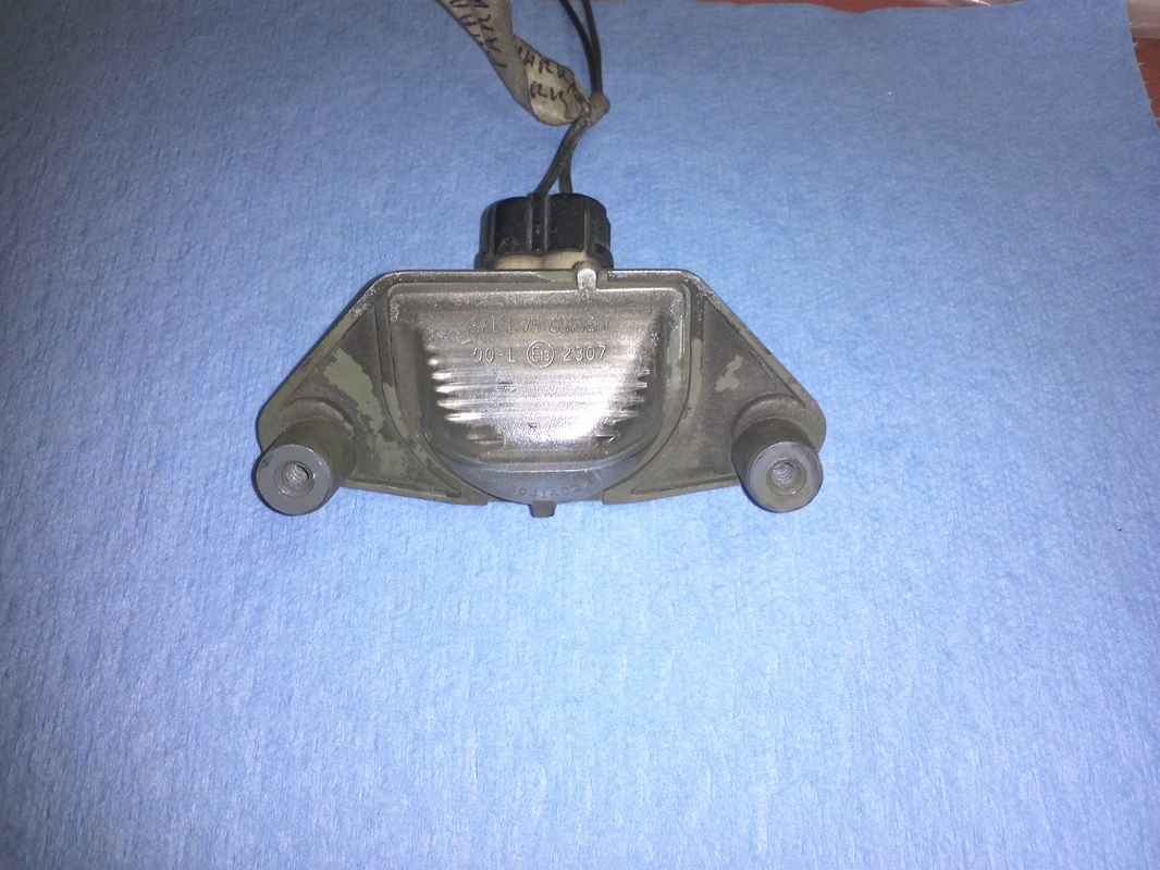
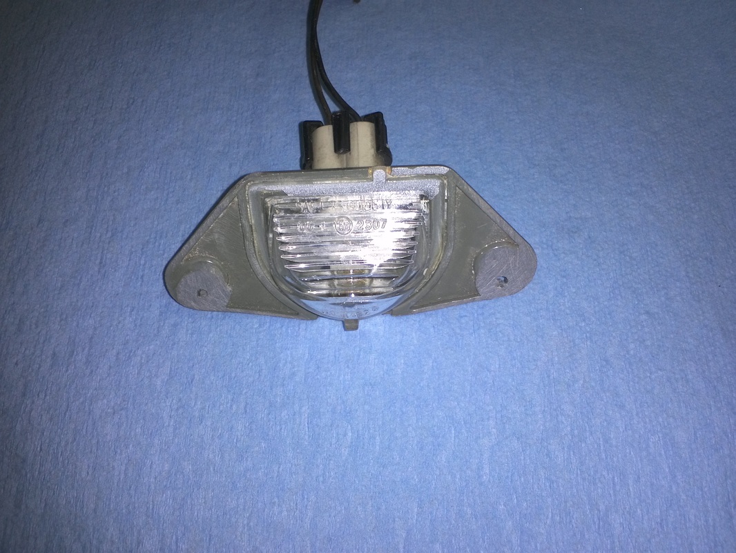
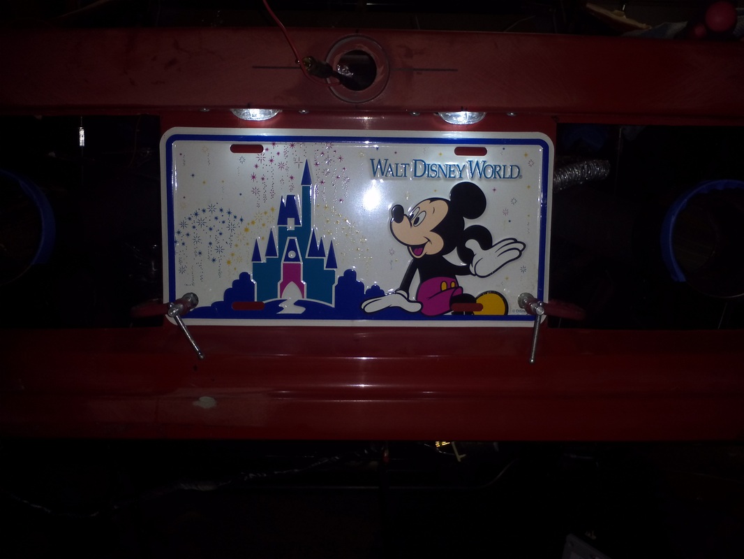
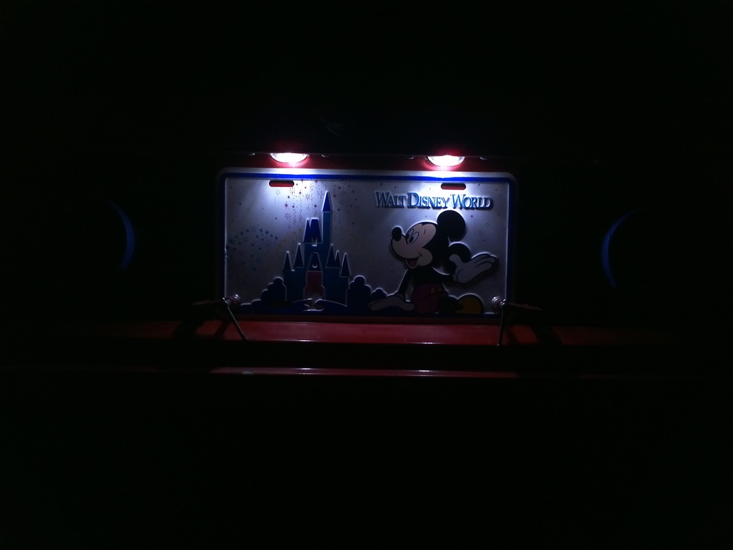
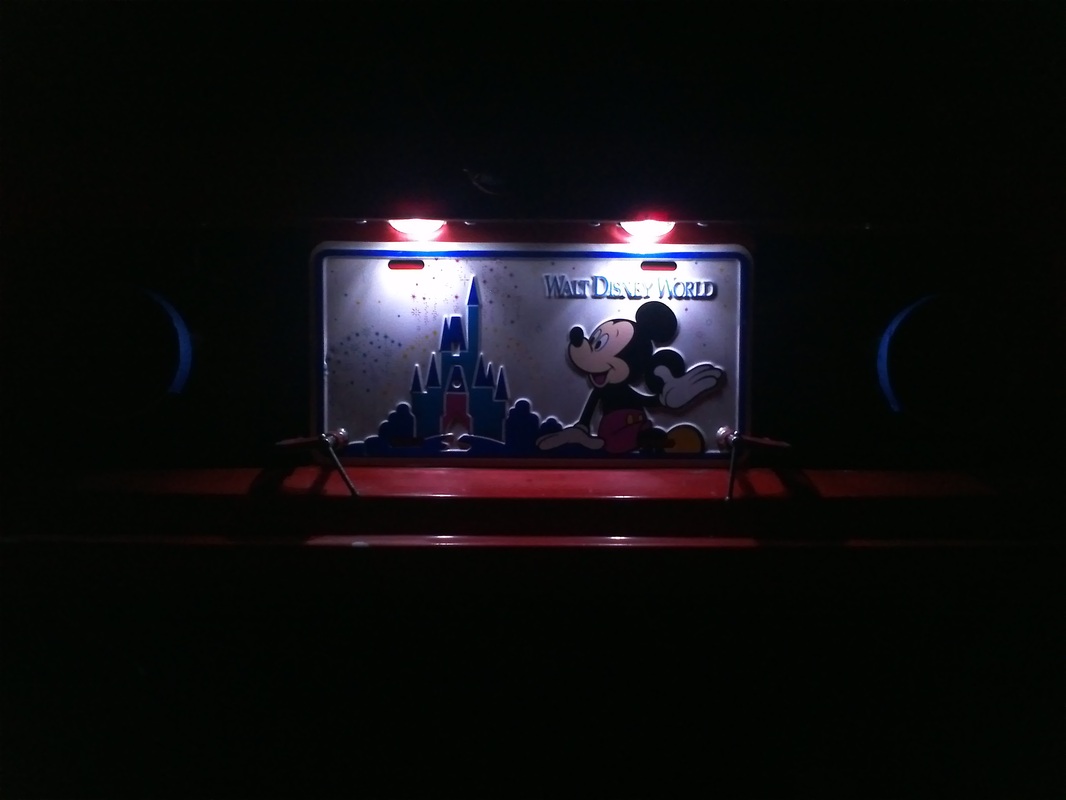
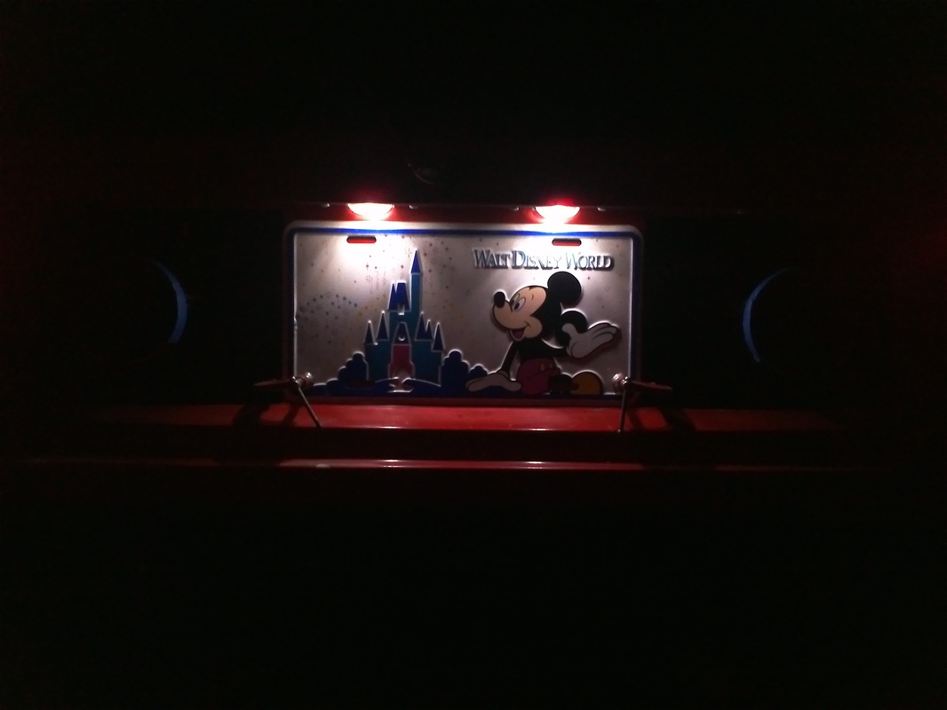
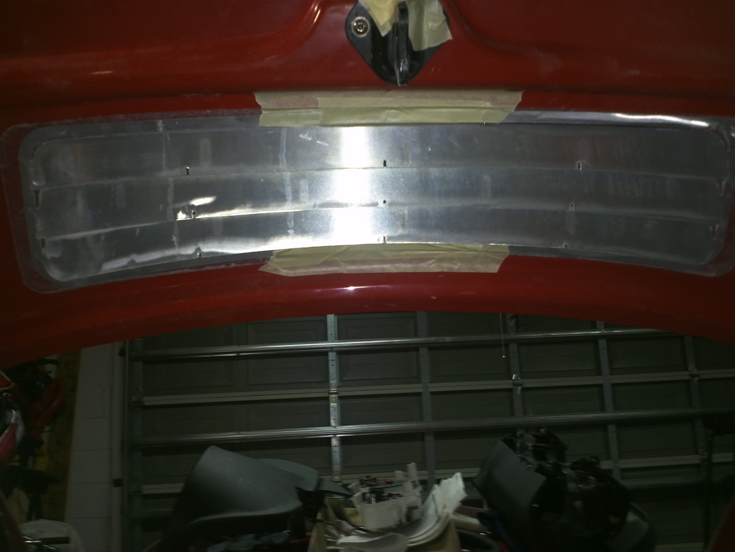
License Plate Lights
I opted not to use the kit included license plate lights. The included lights are a combo part that is also the upper plate bolts. The stock C5 lights had a layer of oxidation on them. So I polished this away with the my rotary tool, rubbing compound and a polish/sealer to shine clear the lens and add some protection. Next then removed the bolt studs from the housings and made a set of templates from them. I taped the templates in place, traced it for back-up and then cut the light opening.


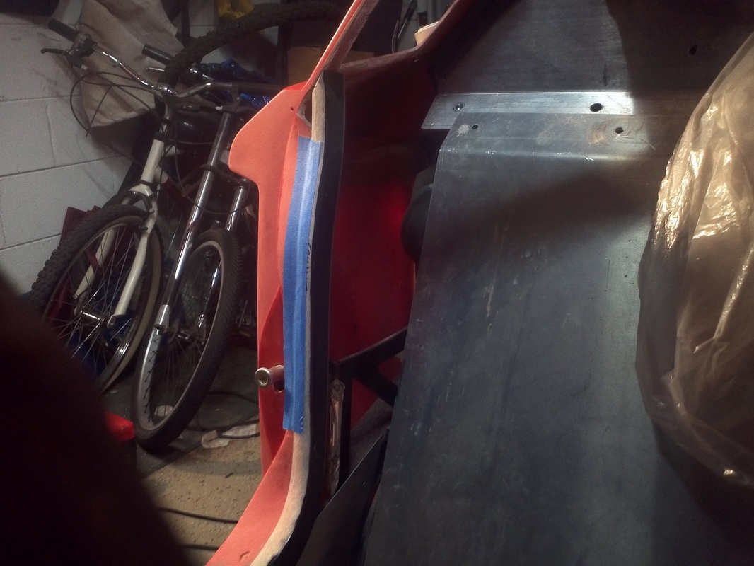
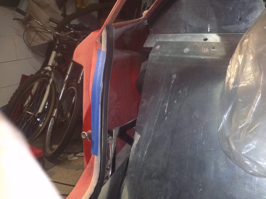
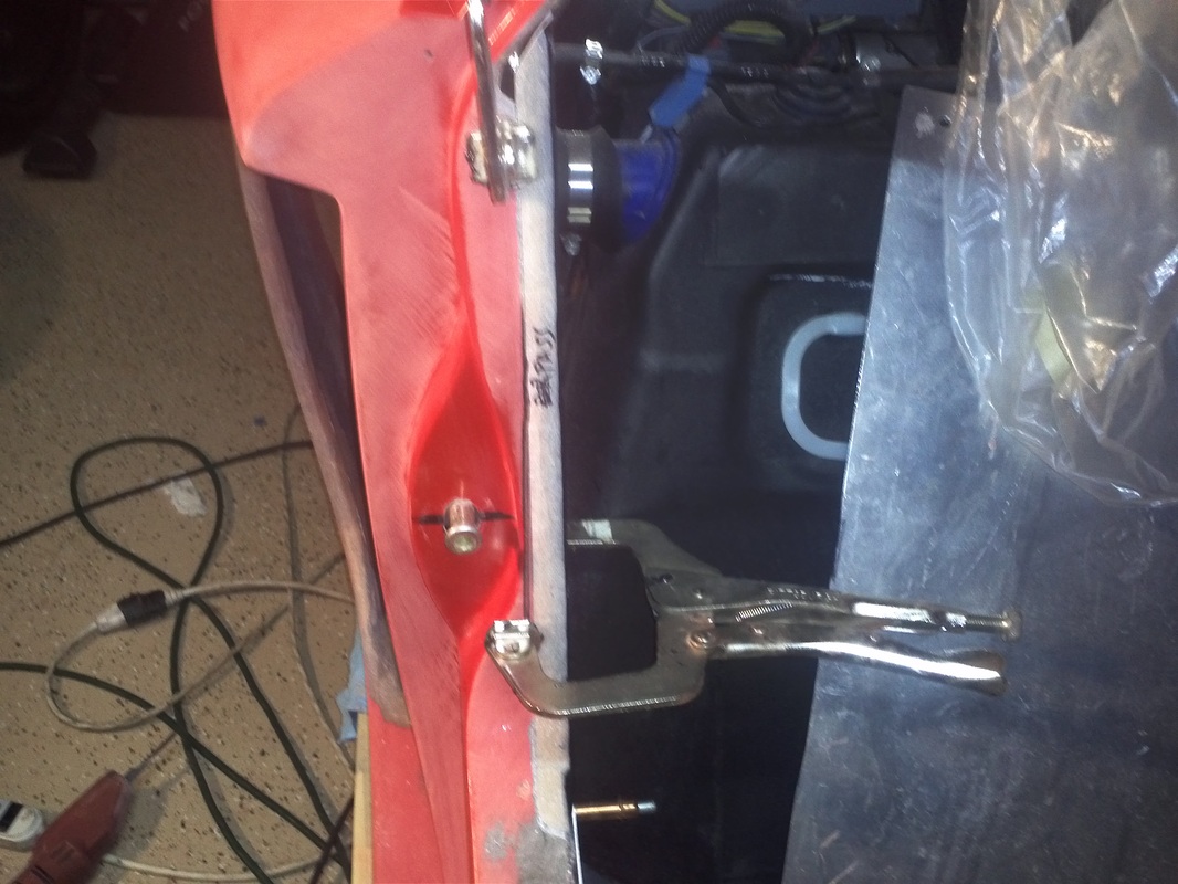
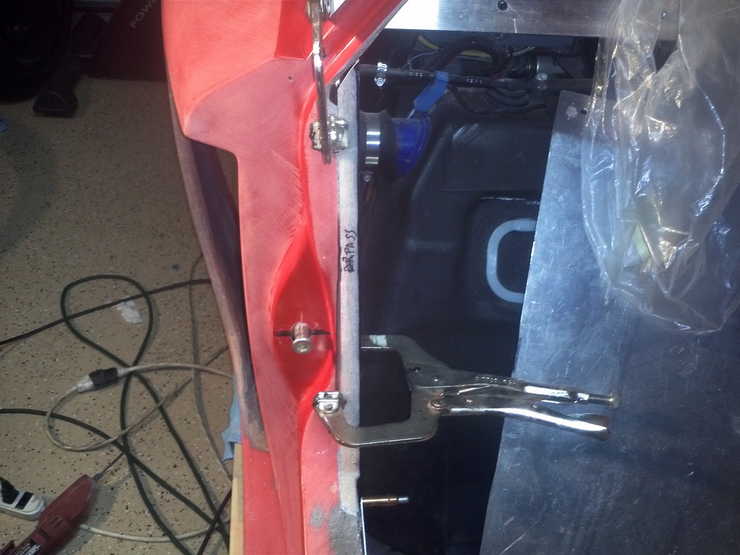
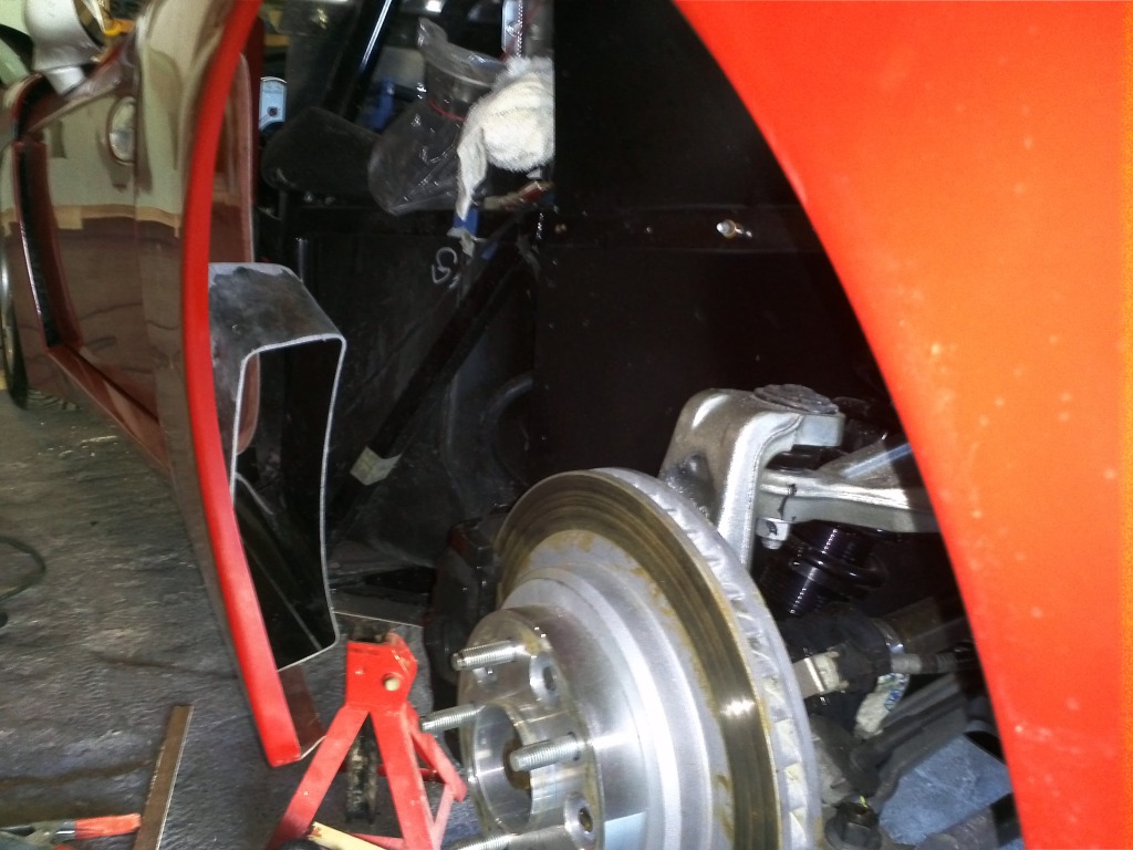
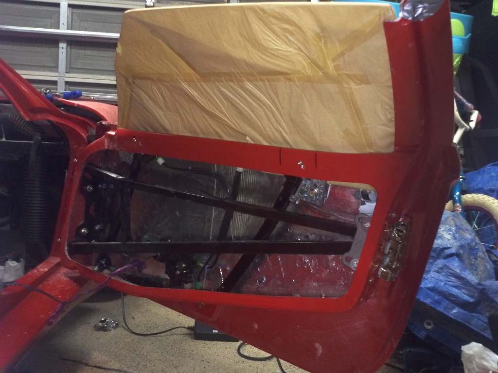
Interior Passenger Side Door Opening Body Extension
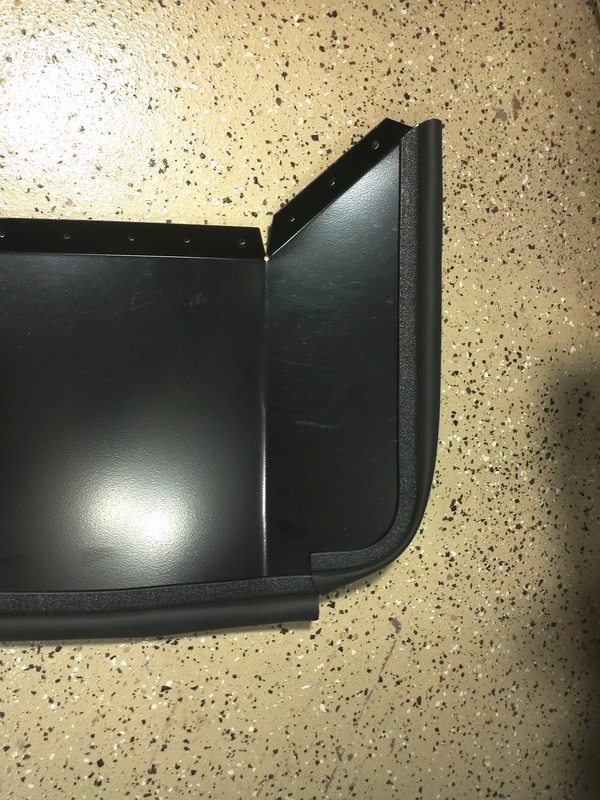
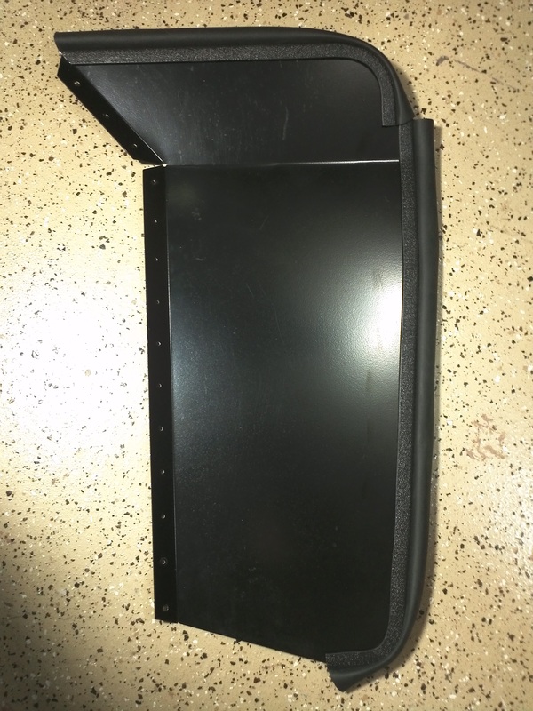
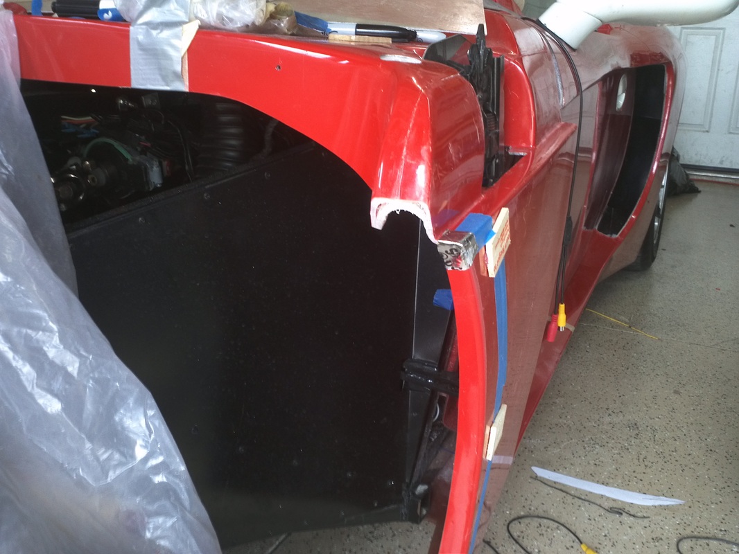
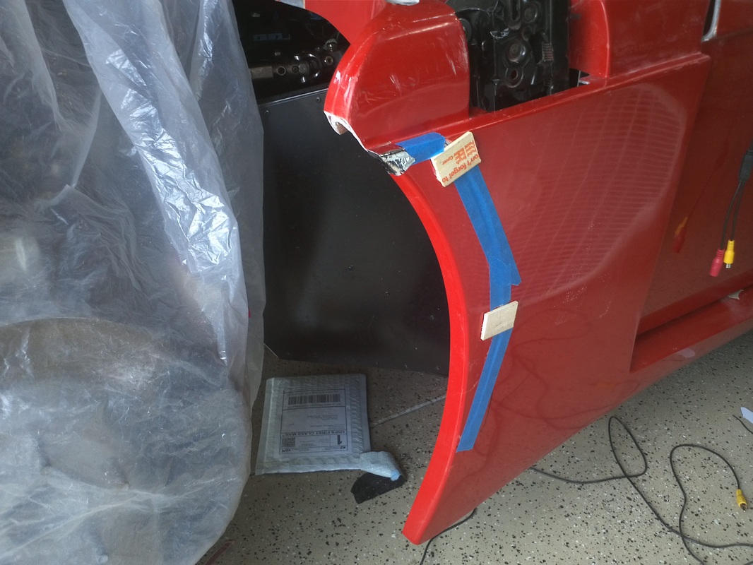
This is part that Tom (Thomas#142) made for his build. It is perfectly matched to the contours of the are where it is to be attached to and includes a nice flange. The flange will then allow for a cleaner, sealed install of the panels that will cover this are. I set and clamped it in place. Then I traced the outline and used it as a guide for removing fg from the body in order to create a cut-out for the piece for a flush fit. I them used 3M8115 to bond the part to the body.


Passenger Side Front Wheel Well closeouts
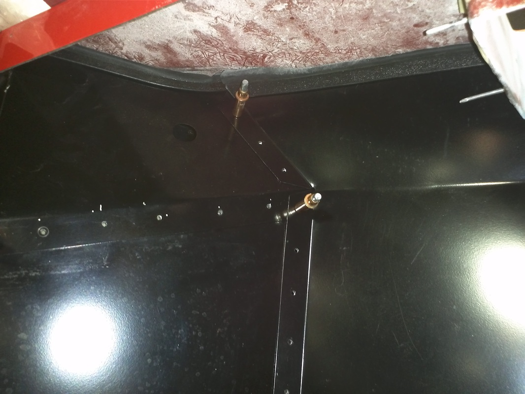
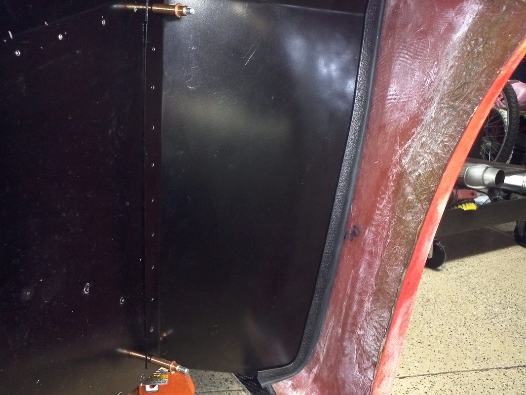
I did a mock up of the front aft wheel well closeout panels. I did do a little scribing and trimming to get the fit I wanted. All but the interior upper piece will receive UPol Raptor Liner. Over all the mock up was uneventful and almost identical to the driver's side mock up. See the driver's side mock up (below) for more detail.


Passenger Side Rocker Mock-up


Passenger Side Door Gap

Driver's Side Wheel Well Closeout Panels
I decided to do the mock up install of the wheel well closeout panels to give me a break from all of the black sanding I have been doing. The panel with the hole (this is where the hood release cable will be) was the first panel. From there I added the small piece. I was then able to take a look and see if I need to trim the first panel. The upper outside ~2 inches was almost touching the body. So I used the grey sharpie to trace what I needed to trim. With the first two panels still in I added the third panel. It required a little trimming to get a uniform gap on the vertical. I then pulled all three panels, trimmed them with the tin snips, added bulb seal and reinstalled them. Initially I was going to add a tap or two to the vertical to support the third panel. It was not necessary as the panel had an extremely solid fit because of the bend, the attachment area angle and a nice fit of the bulb seal.
Prior to the final install, I will apply UPol Raptor Liner to the panels. The second and third will also get a layer of liquid dampener opposite the tire side of the panels.
Prior to the final install, I will apply UPol Raptor Liner to the panels. The second and third will also get a layer of liquid dampener opposite the tire side of the panels.
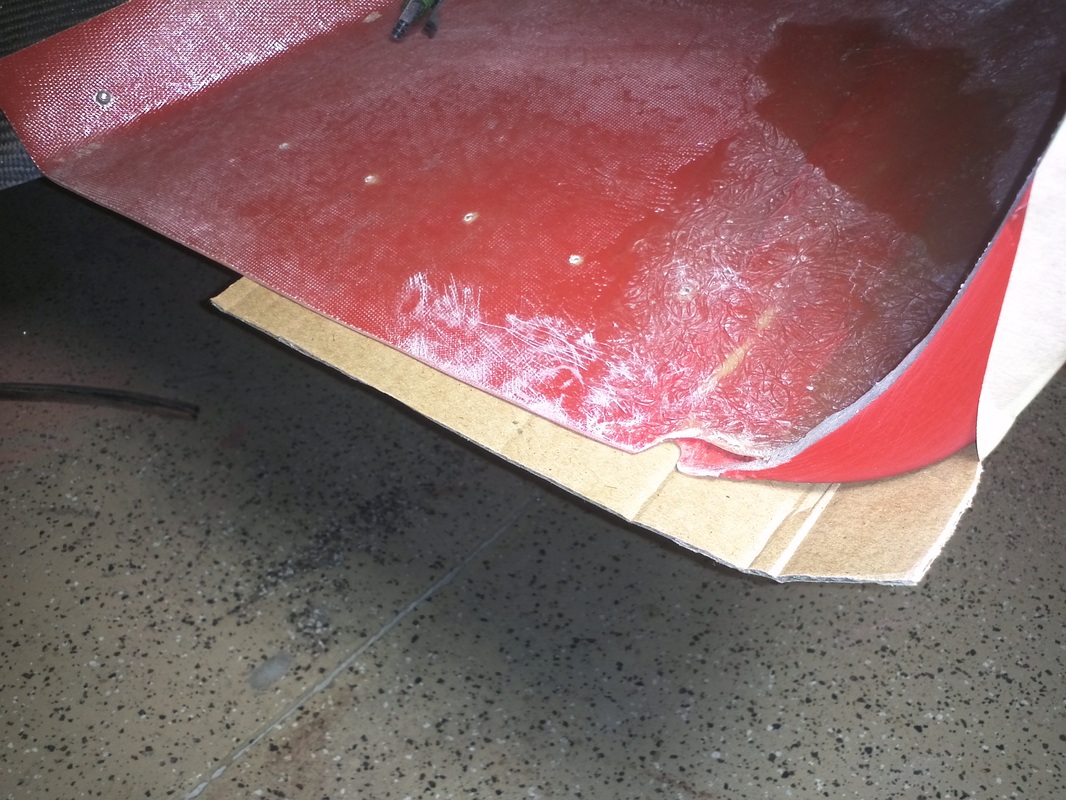
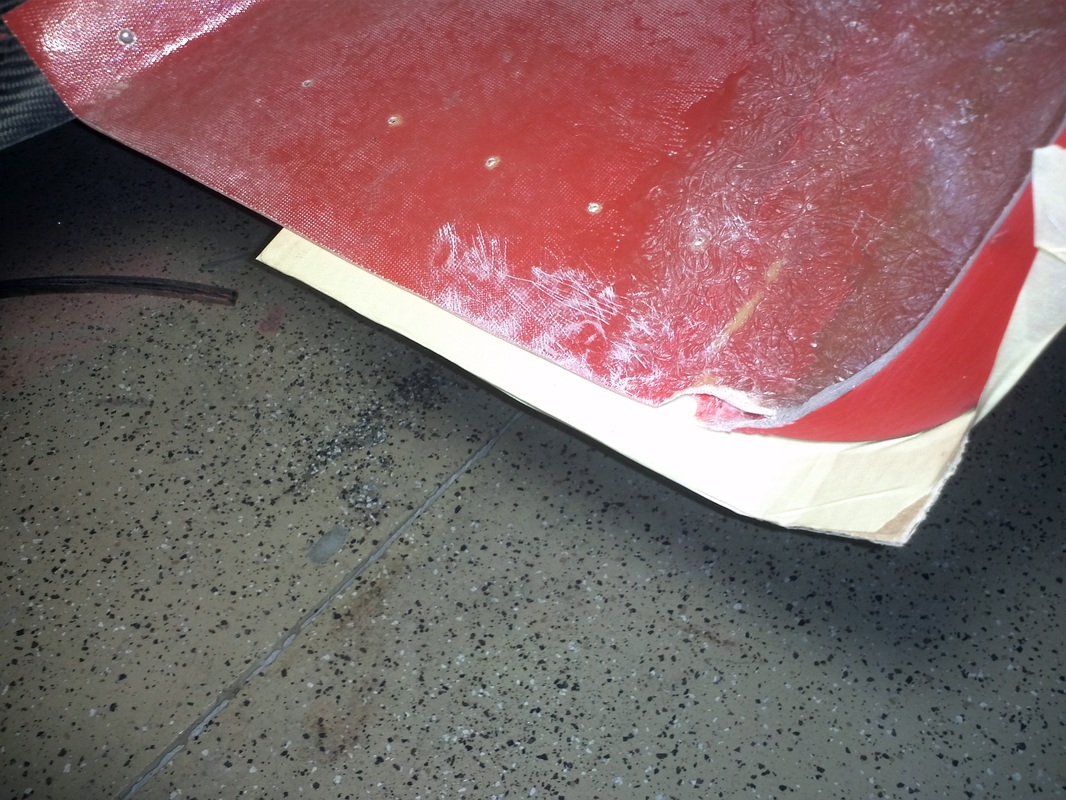
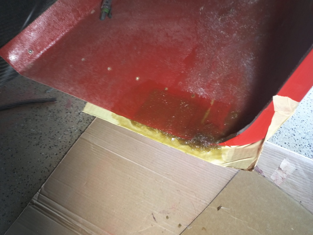
Rear Driver's Side Wheel Well
This appears to be one of the areas where the molds pieces are mated. I roughed and opened the area. I used a simple cardboard w/tape form and then added fg and resin.

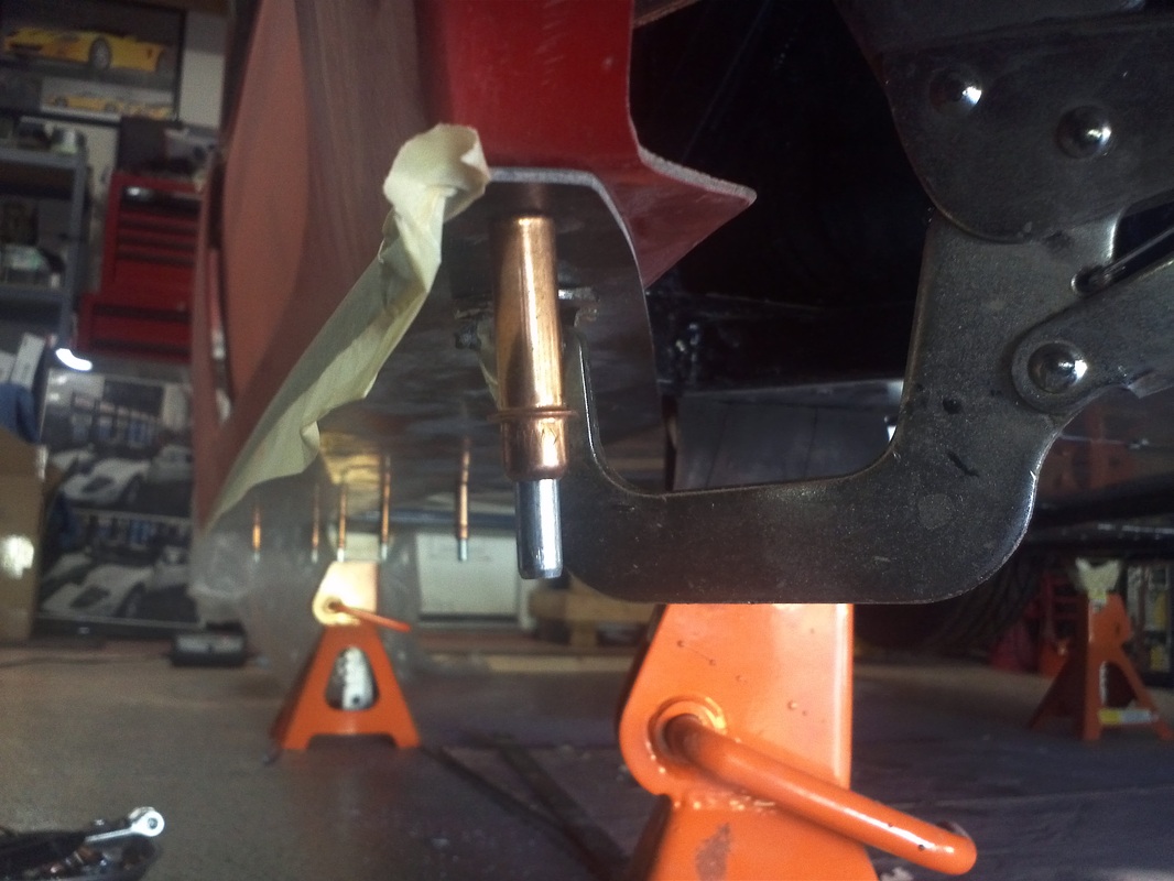
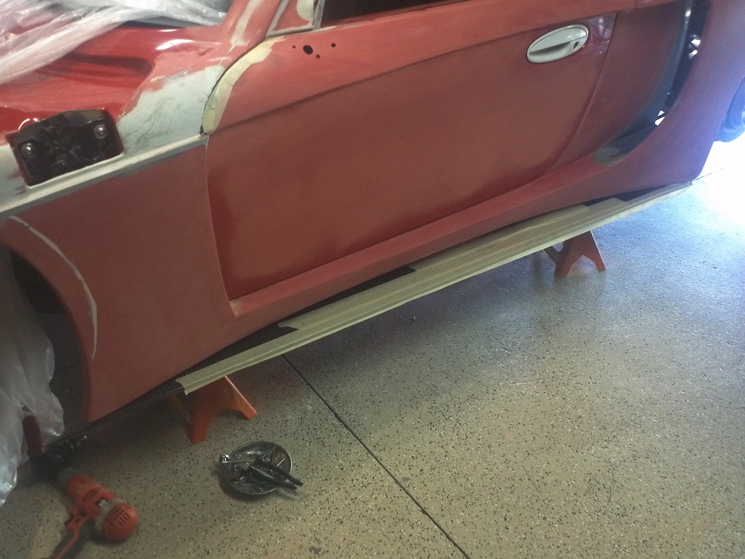
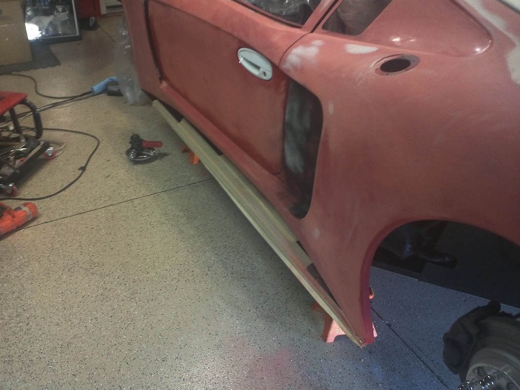
LH Rocker and more Panel Blocking.
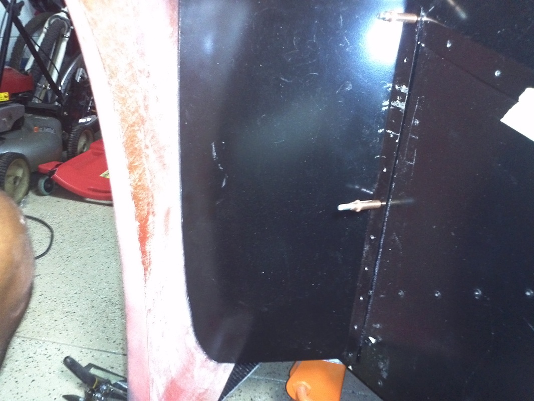
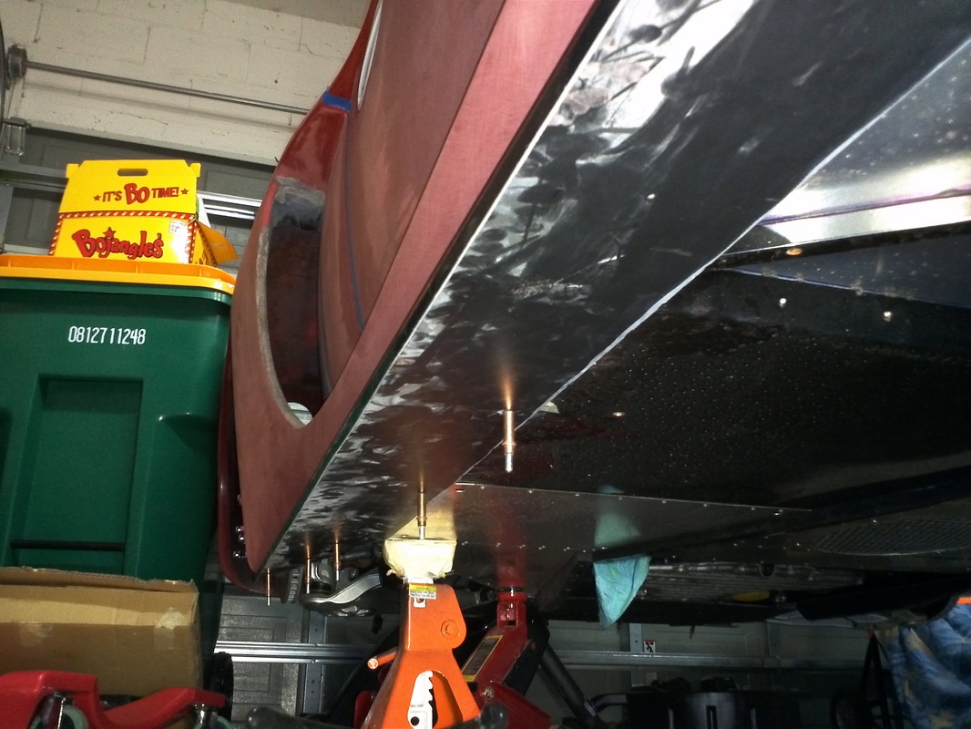
I needed to get the GTM onto the jack-stands so I could install the rocker panels, sand and block through the Full side intake. With the GTm in the air I removed the LH side wheels . After blocking the rocker area of the body I did a mock-up of the LH carbon fiber rocker panel. For the mock-up I used 1/8" holes and clecos. The Final install will consist of stainless bolts, washers and nuts on the for and aft where the rocker is only mated to the body. The remaining, through chassis bar, fasteners will be 3/4" long, 3/16" rivets with stainless washers to better distribute the clamping load (I am also considering tapping the chassis and using stainless bolts and washers. The rocker panel is ~71" so I spaced the clecos at 12". The addition of the Rocker panel stiffens the body, forward and aft of the door nicely. Just as the diffuser does for the back end of the GTM. I will round the for and aft ends so the rocker panel has a smooth flow.
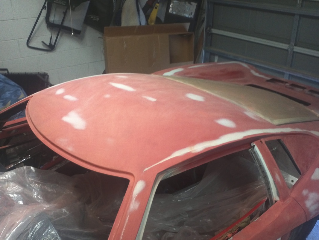
I competed the initial blocking, after Rage, of the roof as well as the remaining flashing areas and started on the LH side door. The LH door was close to flat as the RH side was and there were only a few spots that required Rage.
I competed the initial blocking, after Rage, of the roof as well as the remaining flashing areas and started on the LH side door. The LH door was close to flat as the RH side was and there were only a few spots that required Rage.

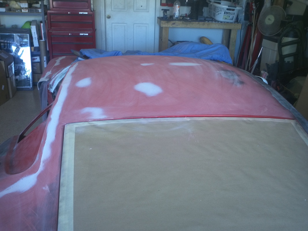
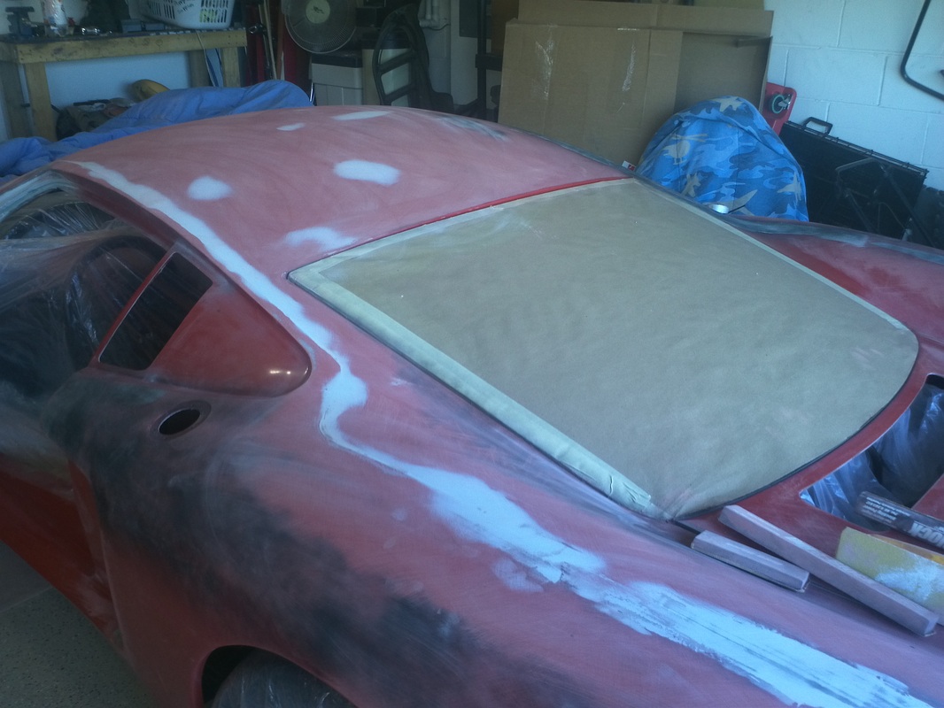
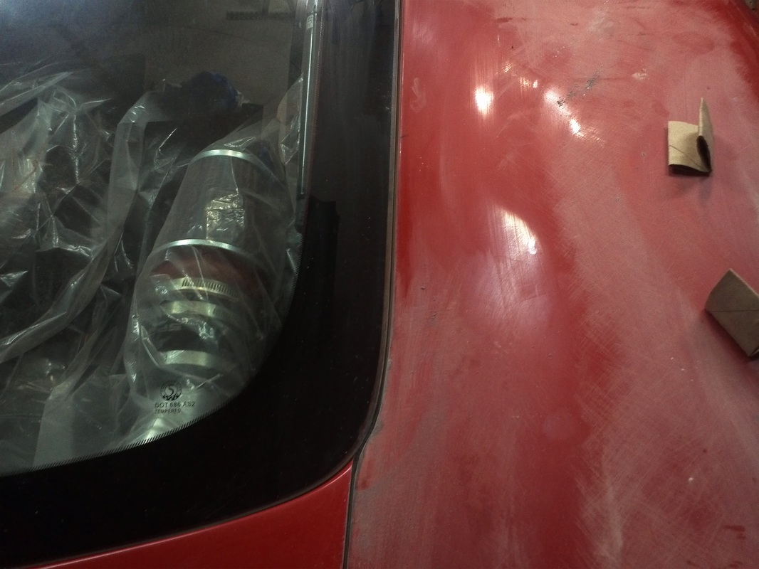
Hatch Glass Final Fit and Adjust for Bodywork
|
I installed a slip-on bulb seal to the hatch area. From there I made a few adjustments to find the happy-median for the hatch so I could precede with the body work.
I shot a quick walk-around of the hatch with my phone. |
|


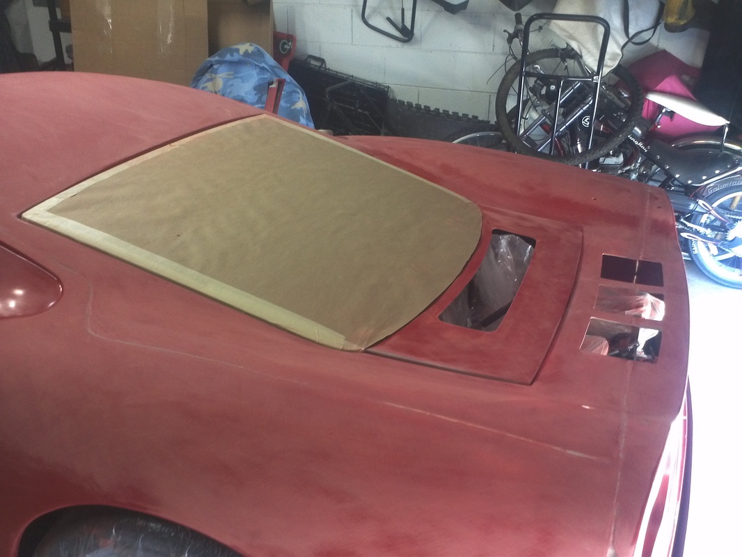
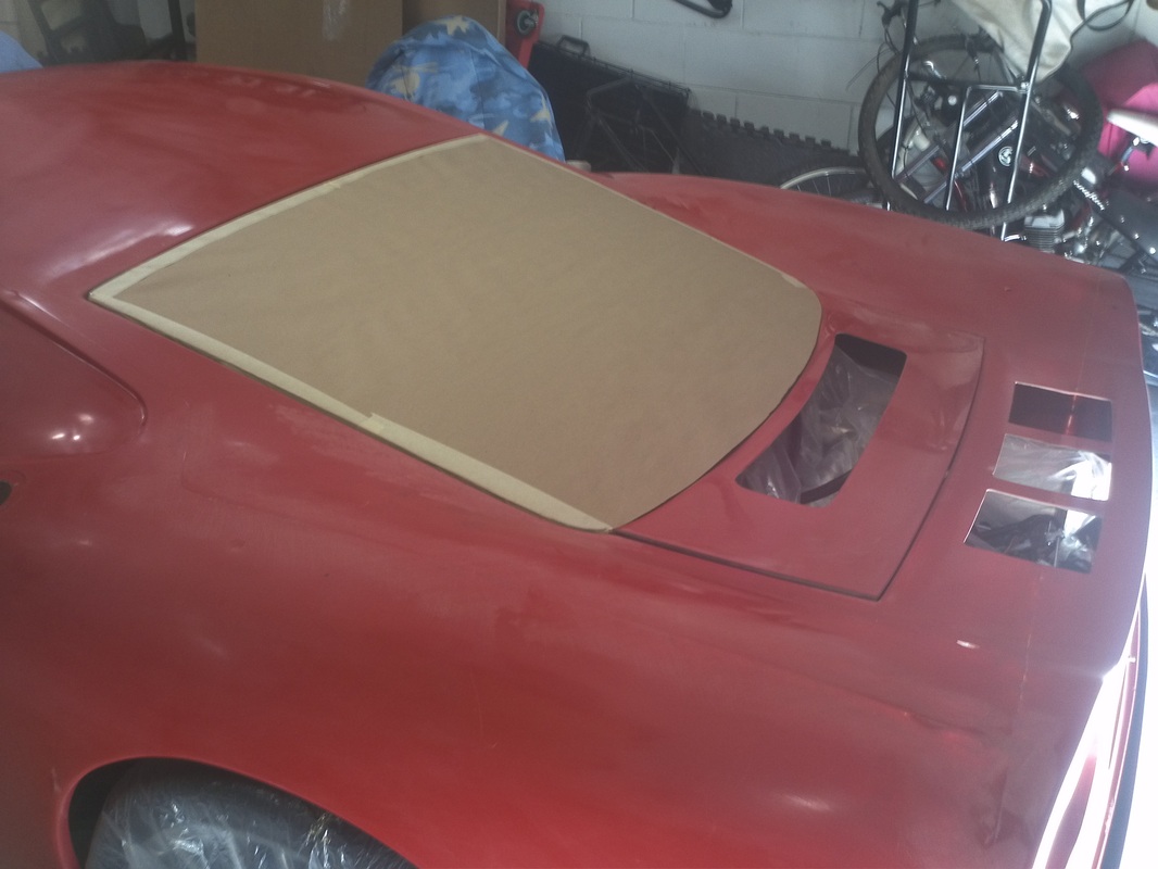
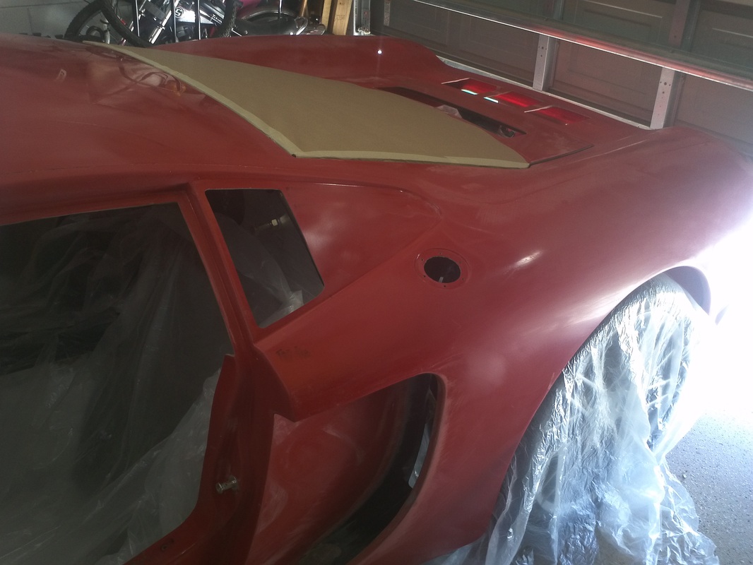
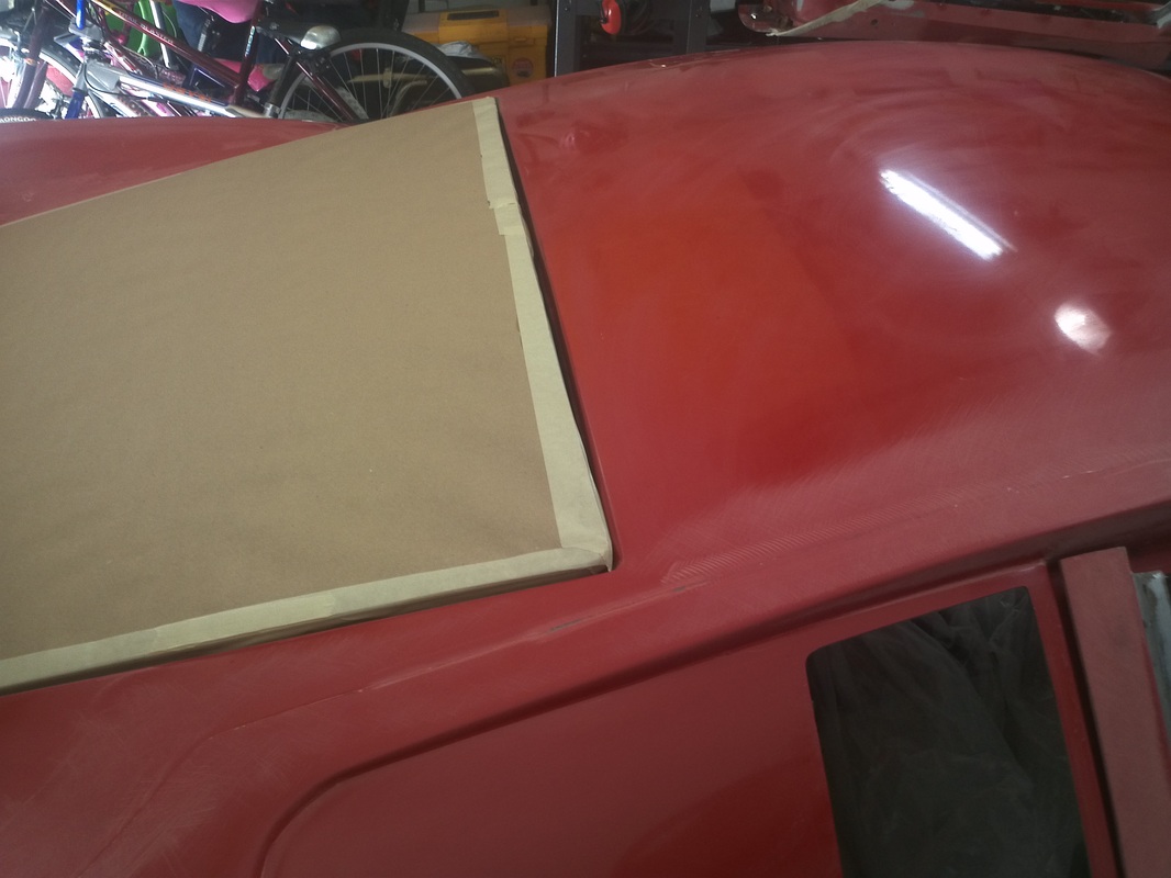
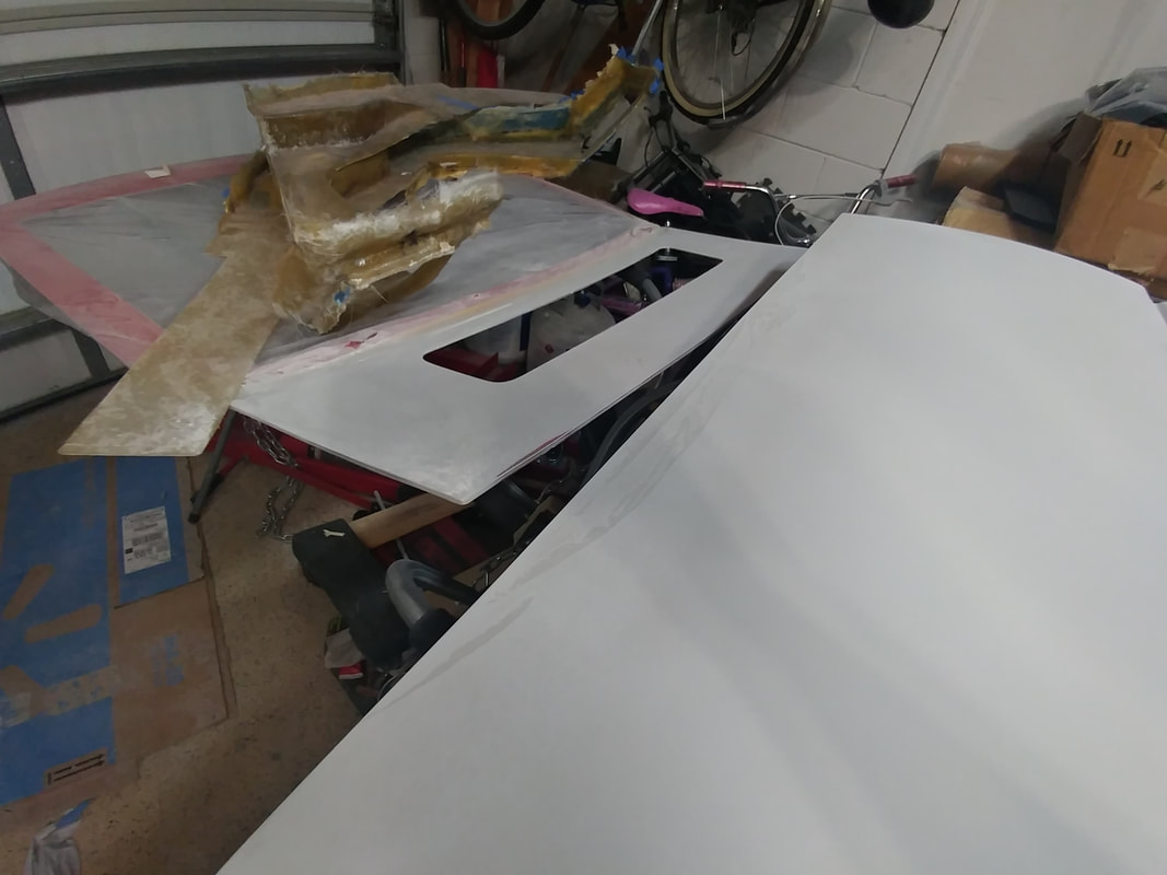
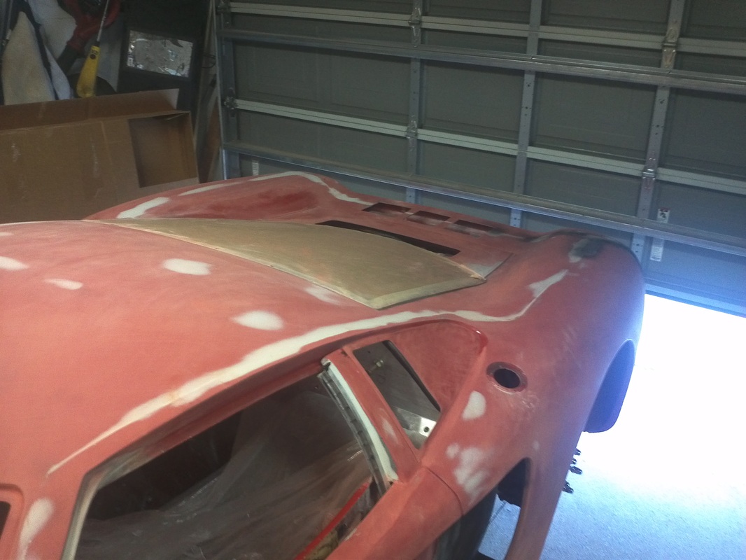
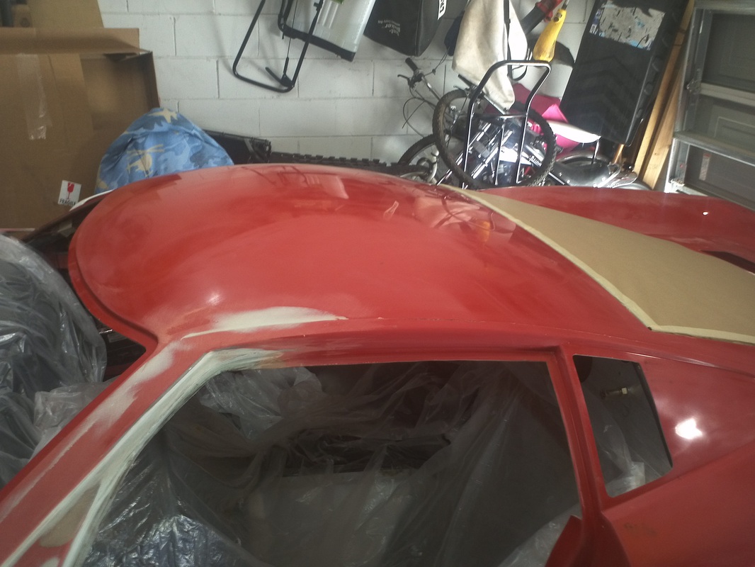
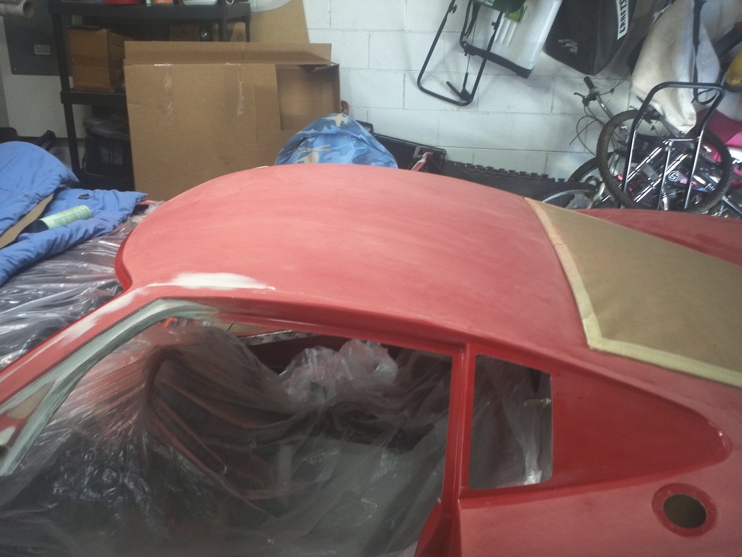
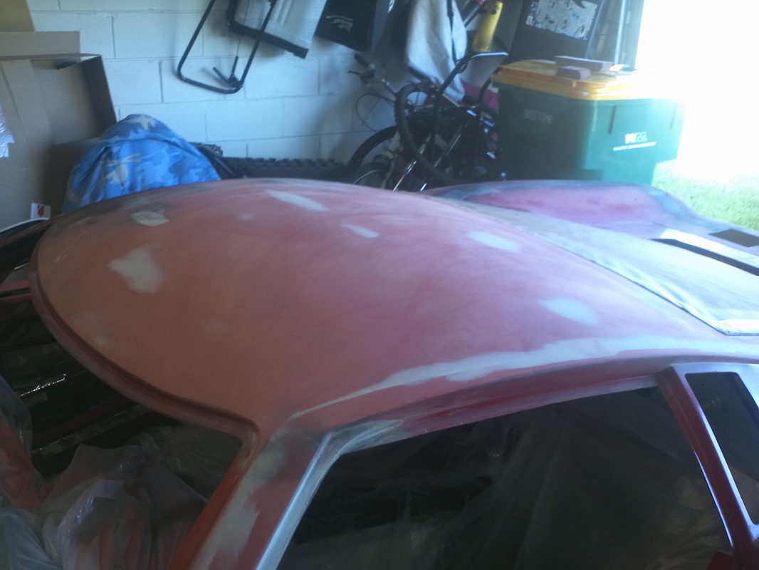
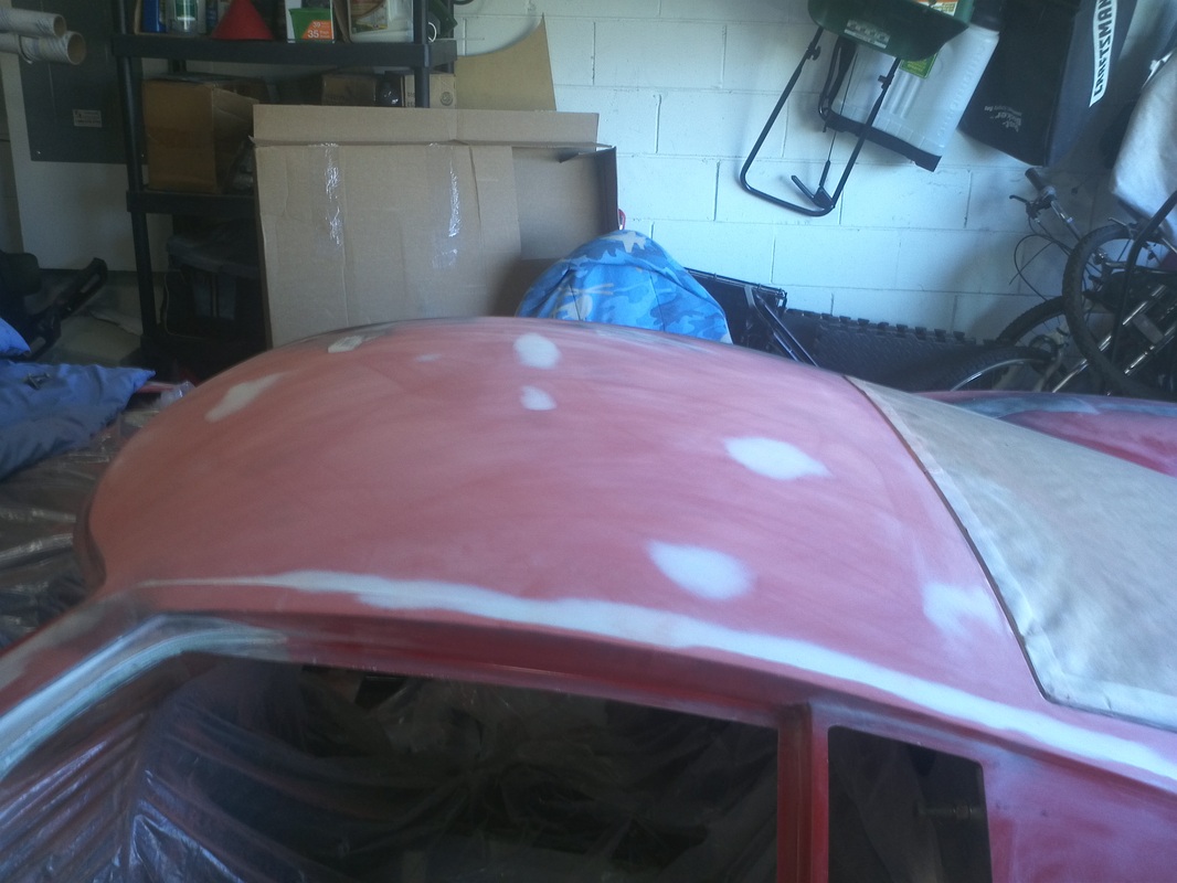
Blocking the Roof
I started blocking the hood. There were a few low spots, but overall it was very close to flat after my initial blocking.


Driver's A Pillar Rework
I trimmed this area while fitting the door and now I need to fine tune it to match the passenger side. I did this by measuring the passenger side and creating a simple form on the door that matches the opening on the passenger side. After prepping the area I closed the door and added Rage to the area.

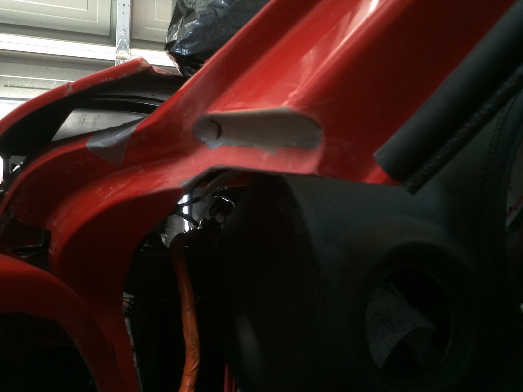
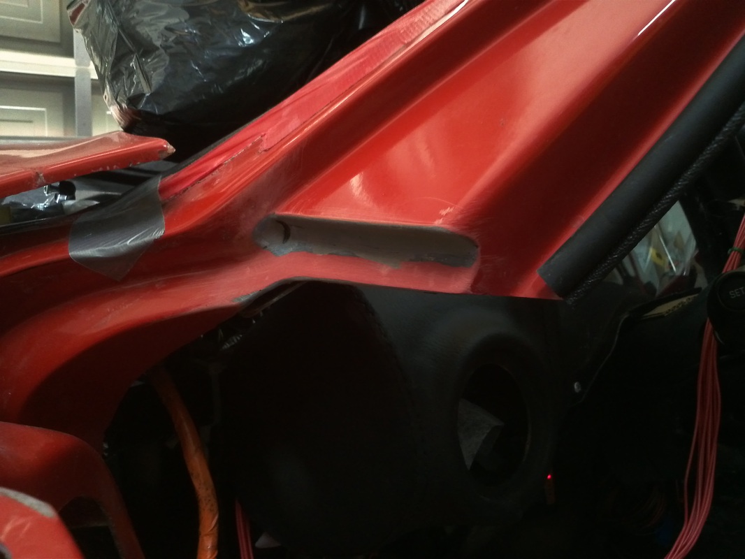
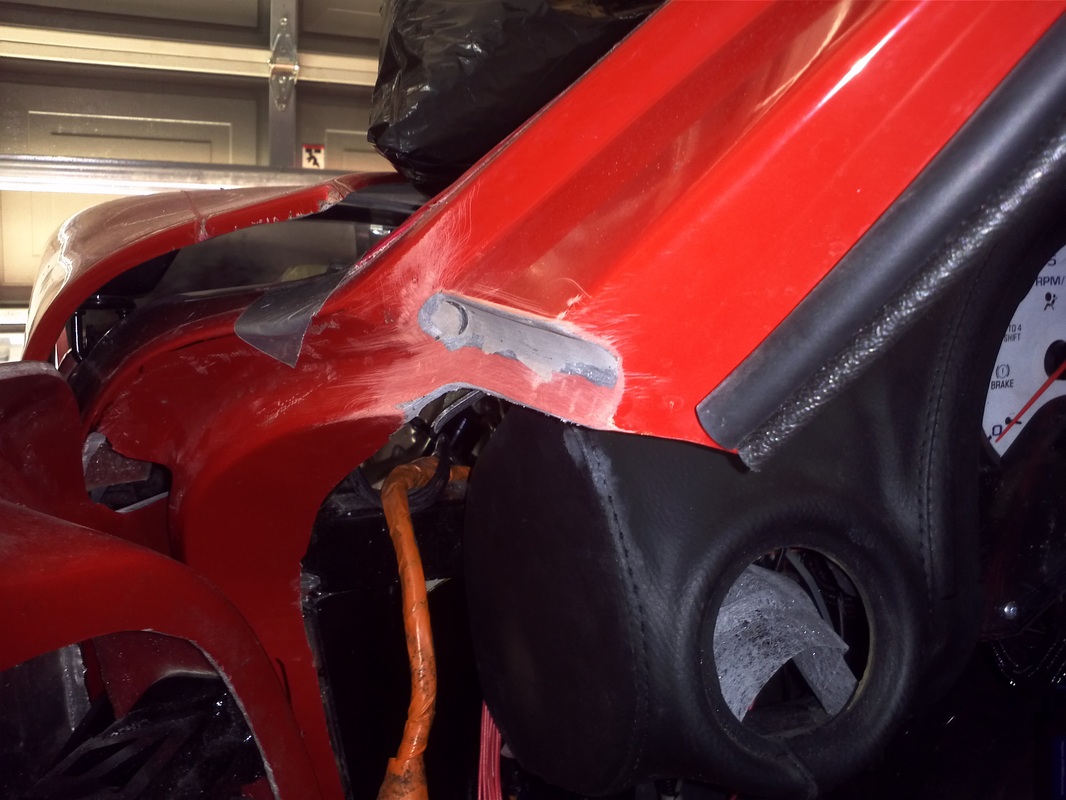
Forward Door Opening Rework
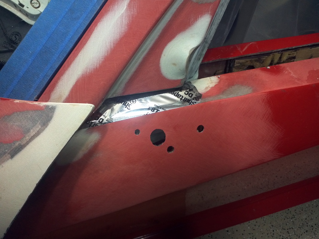
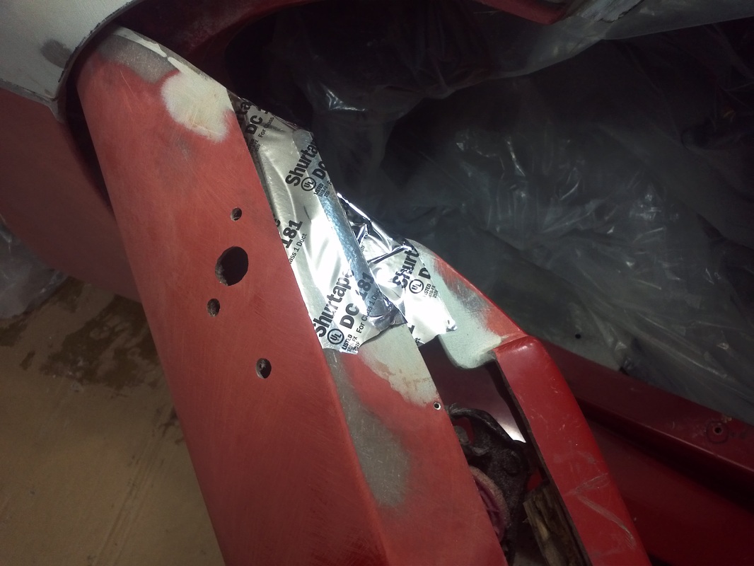
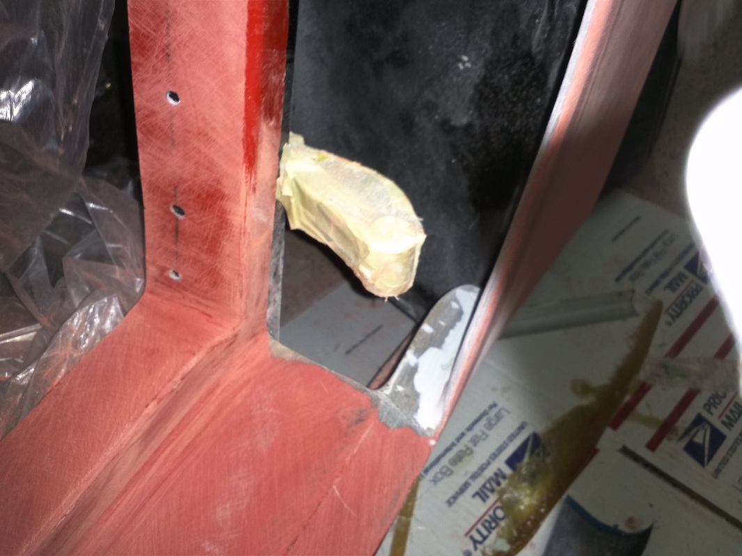
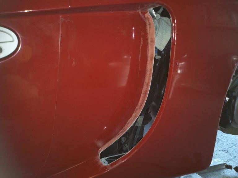
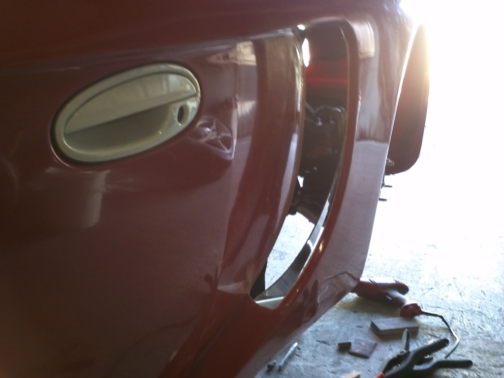
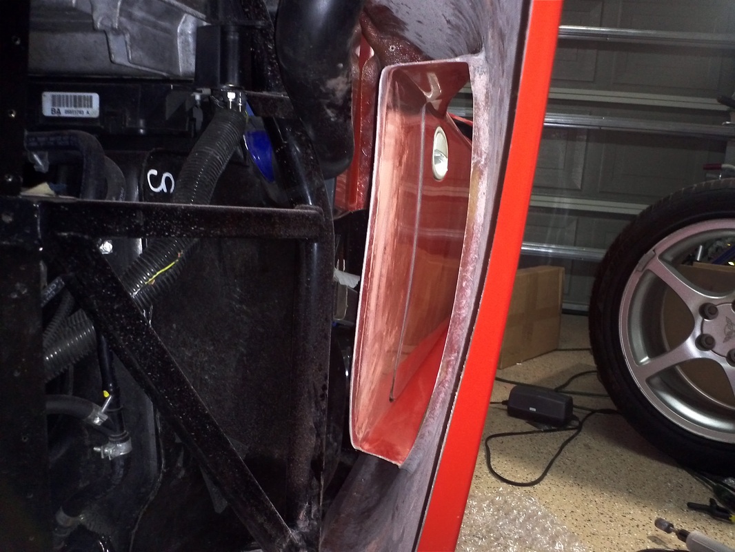
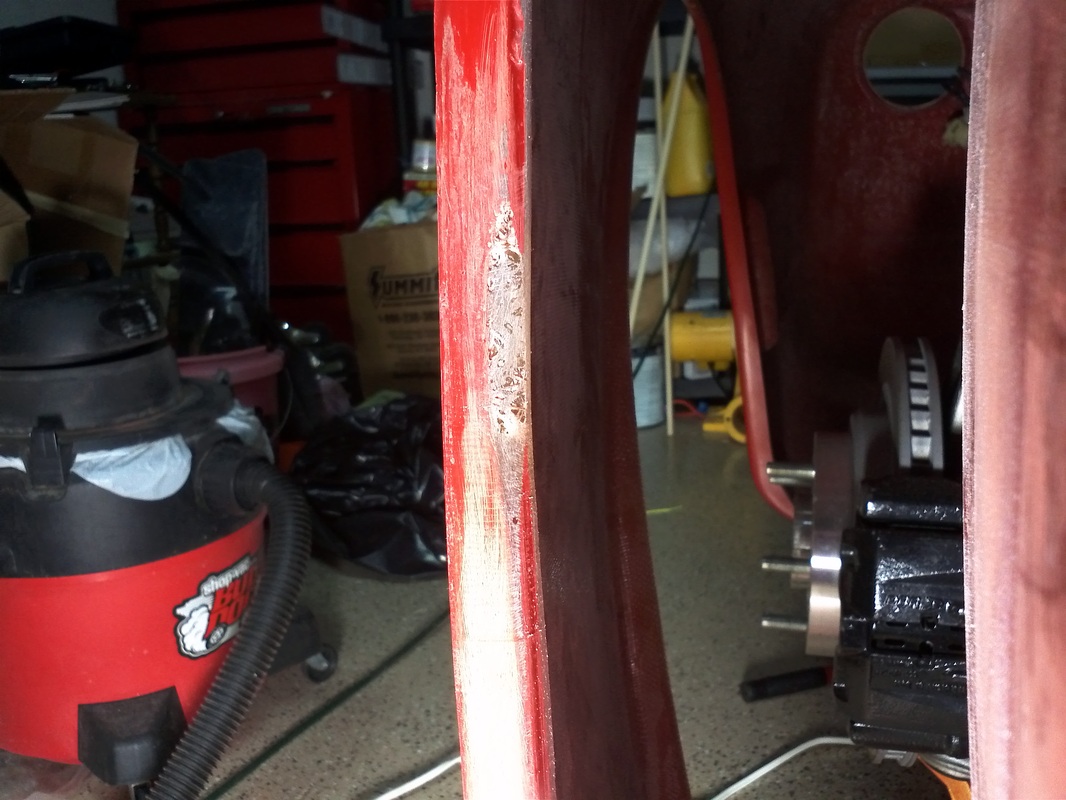
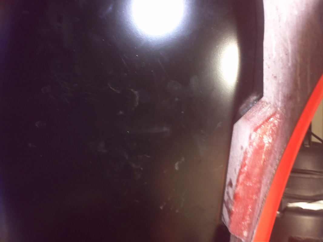
The vertical opening in front of the door was cut short and very thin in some areas. There was no way of sanding it down to a nice rounded finish. I added 6 layers of mat and resin to the inside to give me a thicker area to sand and finish.
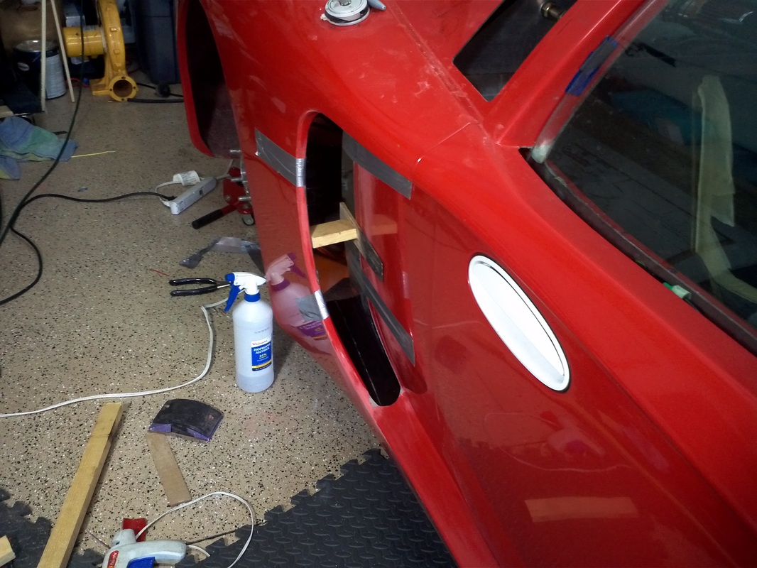
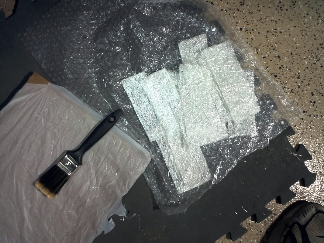
Gene (Fastthings on the forum) added an extention to the forward door opening that adds to the finished look and eleviates seeing a void when you look there so I decided to do the same. I bonded a strip of fg (Tom and I previously made ~1.5sf of it) to the underside of the body.
Gene (Fastthings on the forum) added an extention to the forward door opening that adds to the finished look and eleviates seeing a void when you look there so I decided to do the same. I bonded a strip of fg (Tom and I previously made ~1.5sf of it) to the underside of the body.
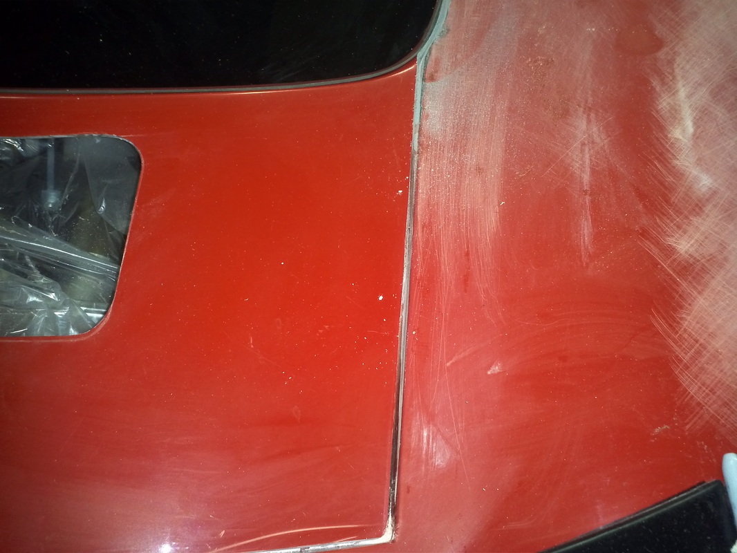
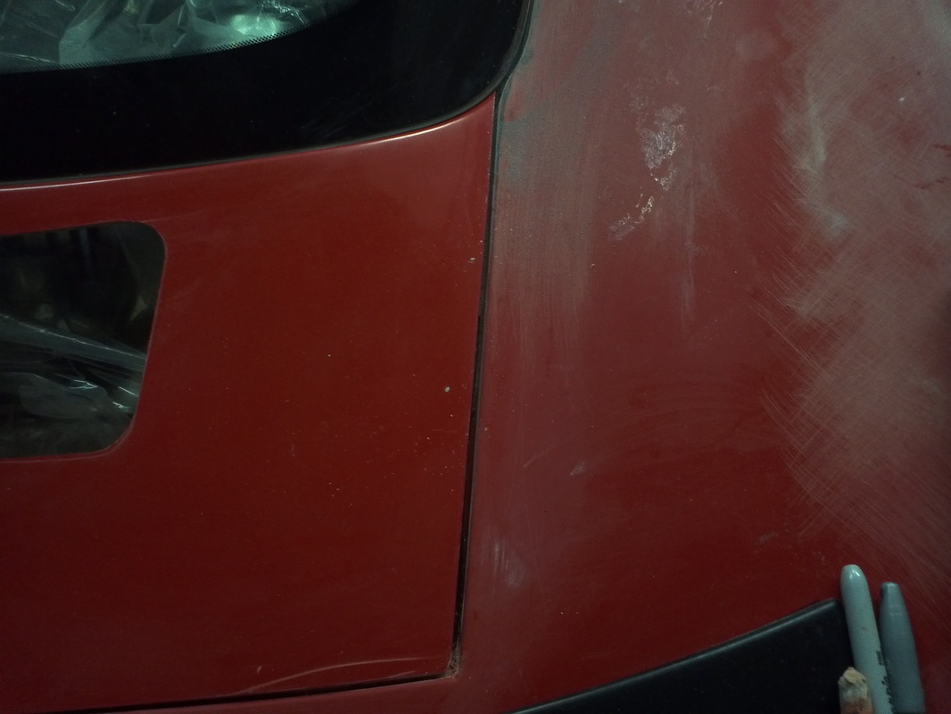
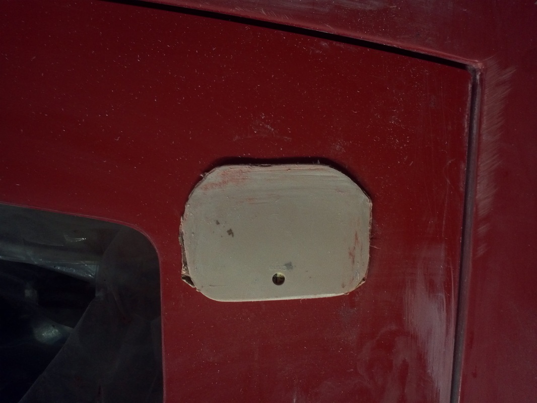
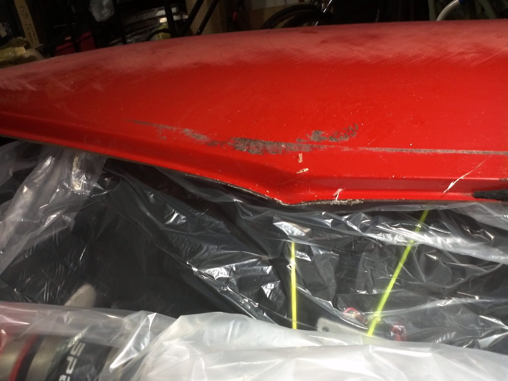
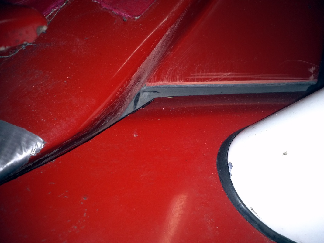
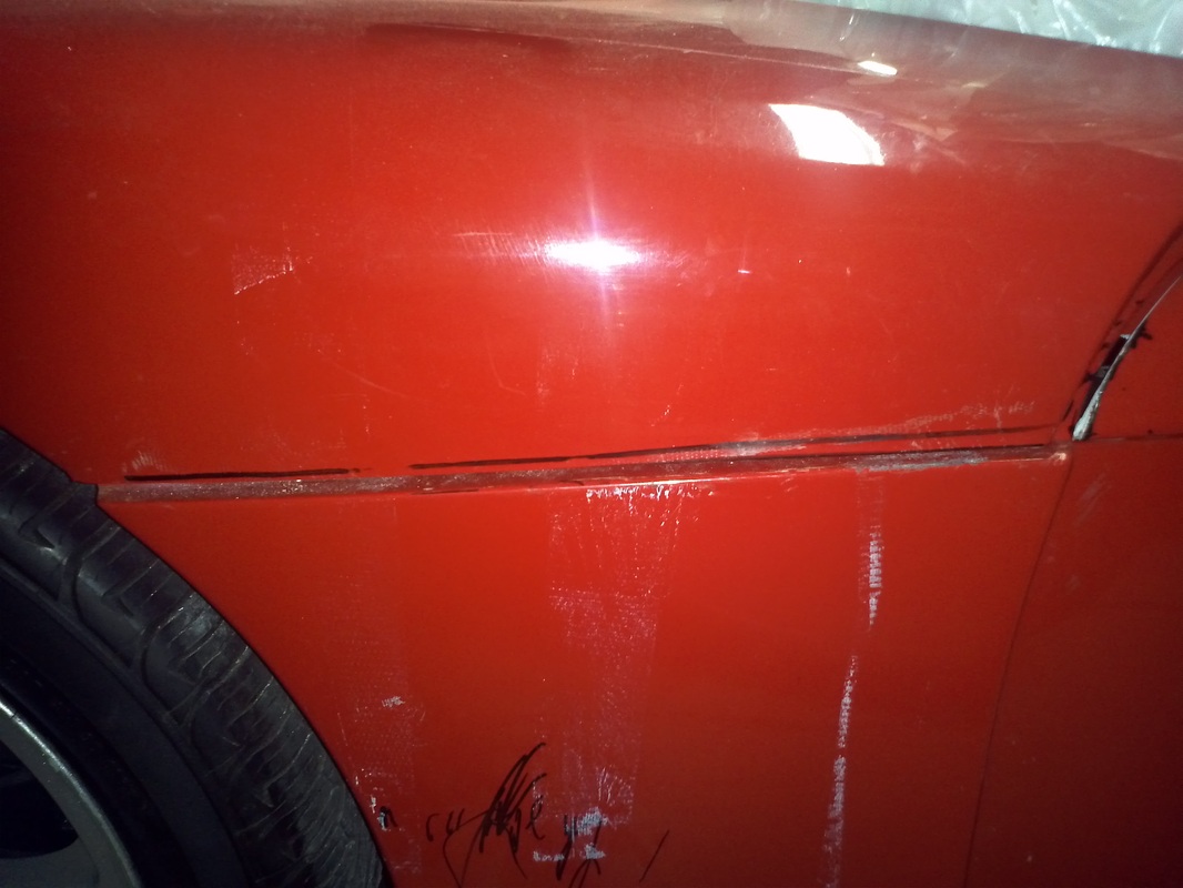
Rework of the Passenger Door Gap. Filling the Emblem Recess.
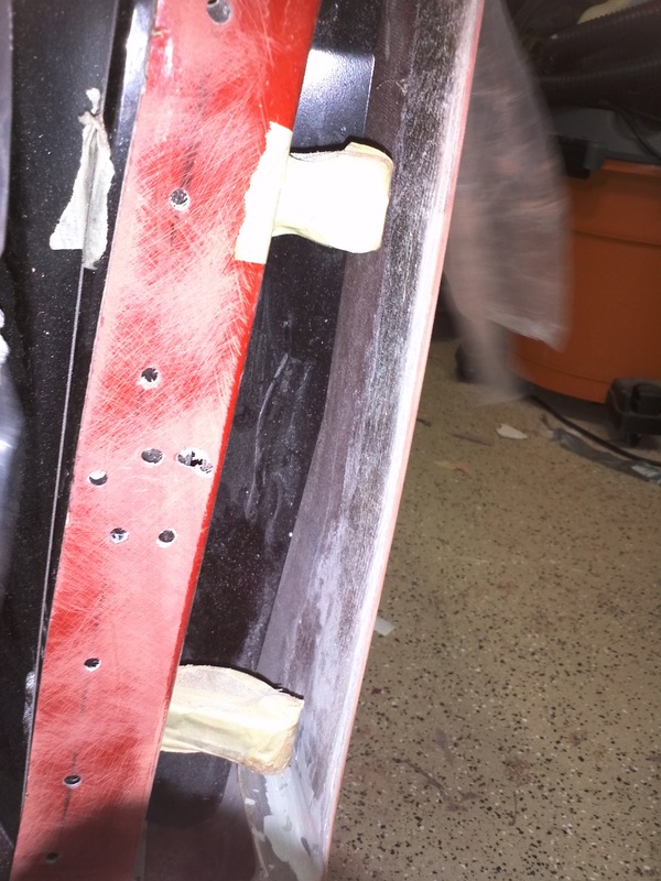
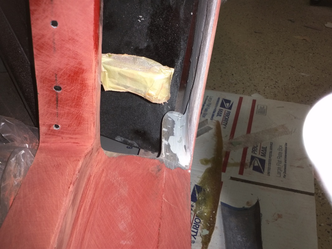
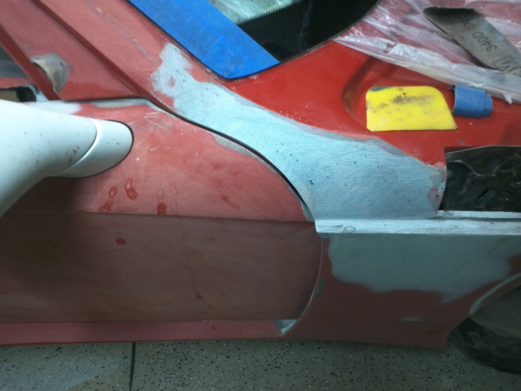
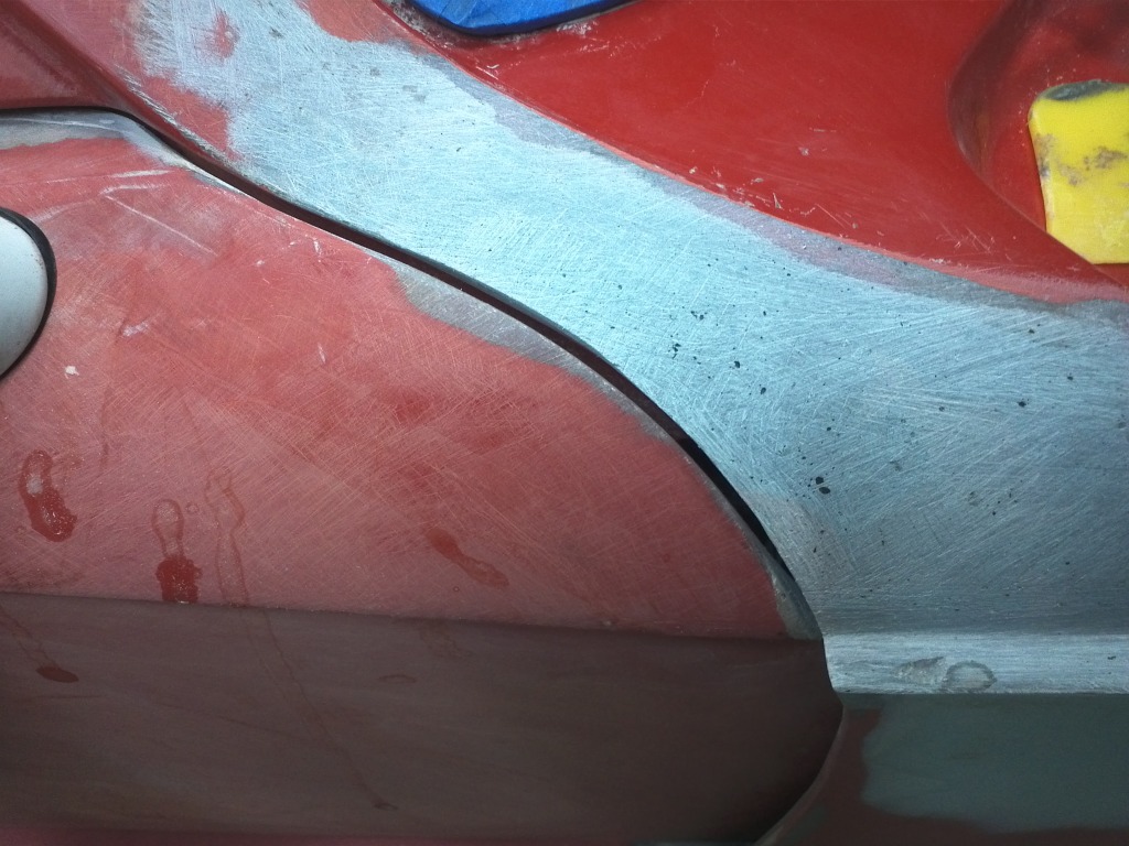
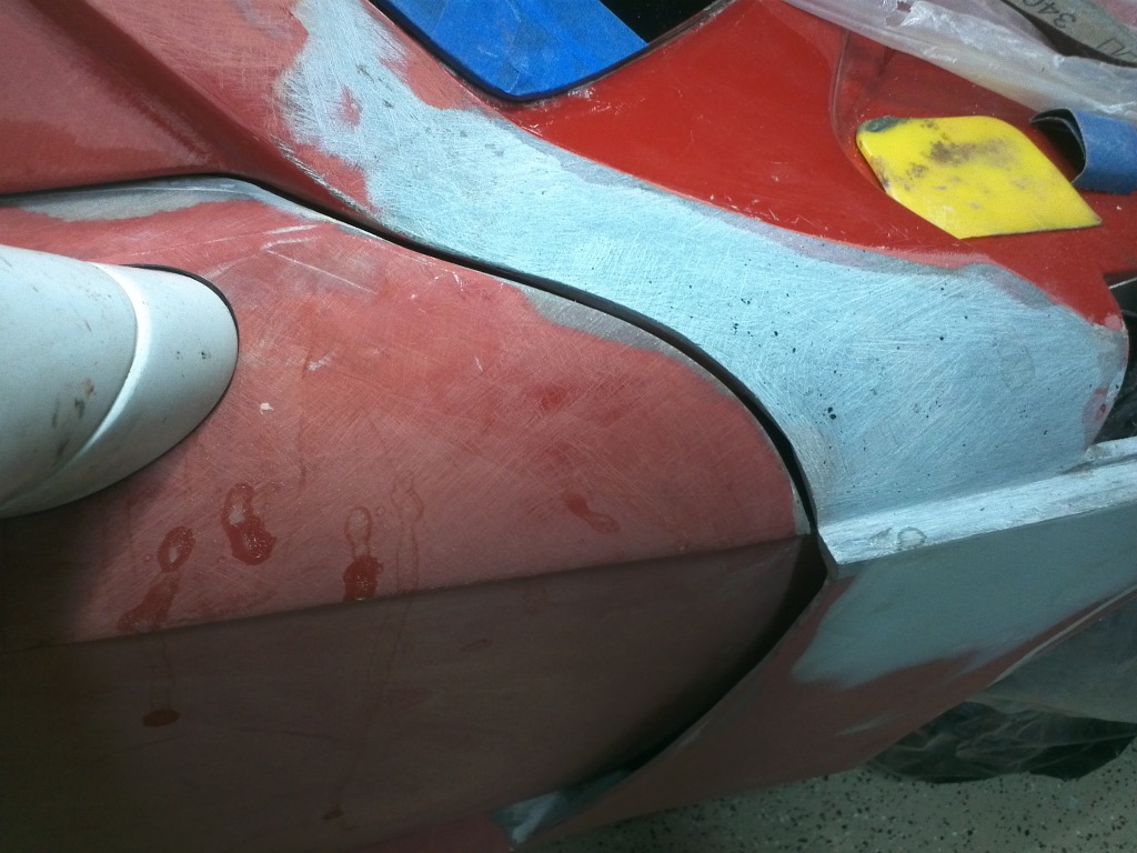
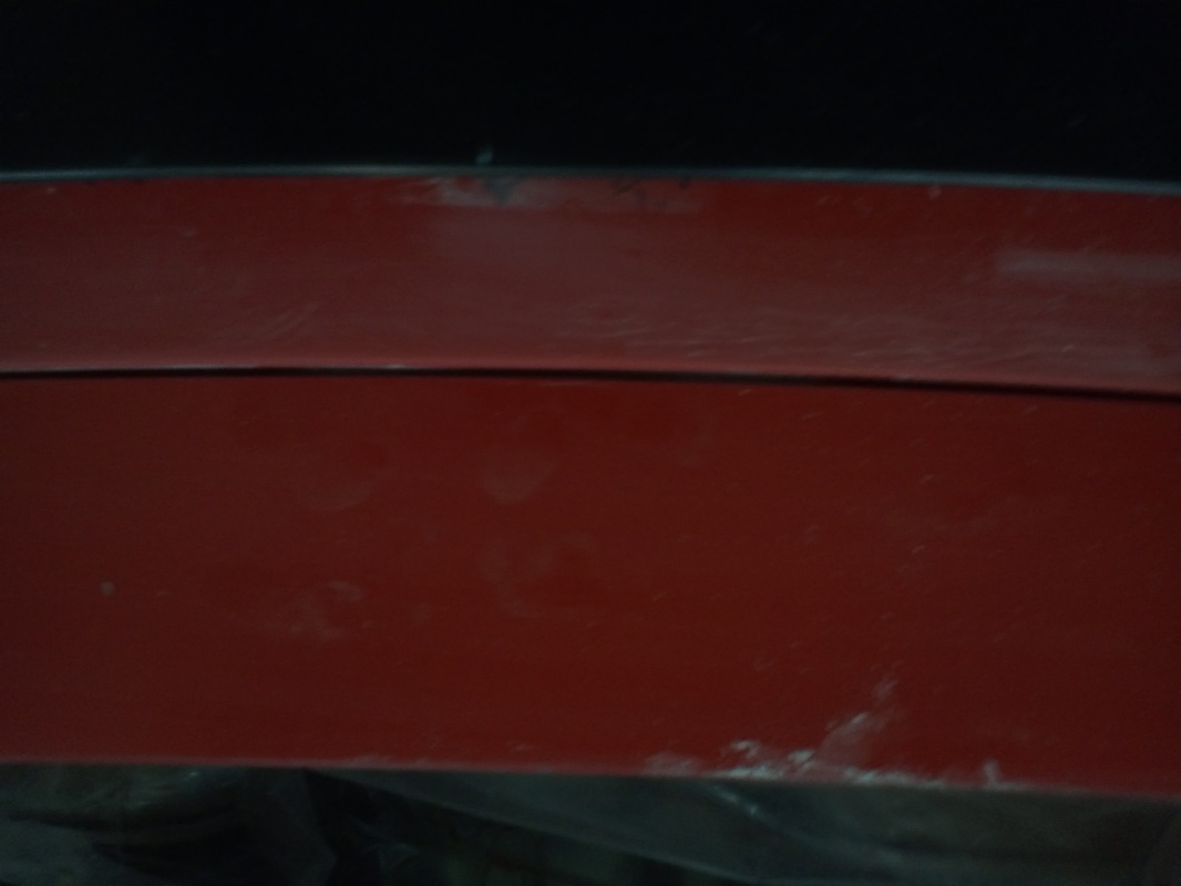
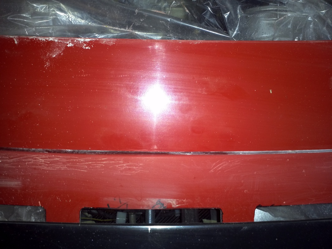
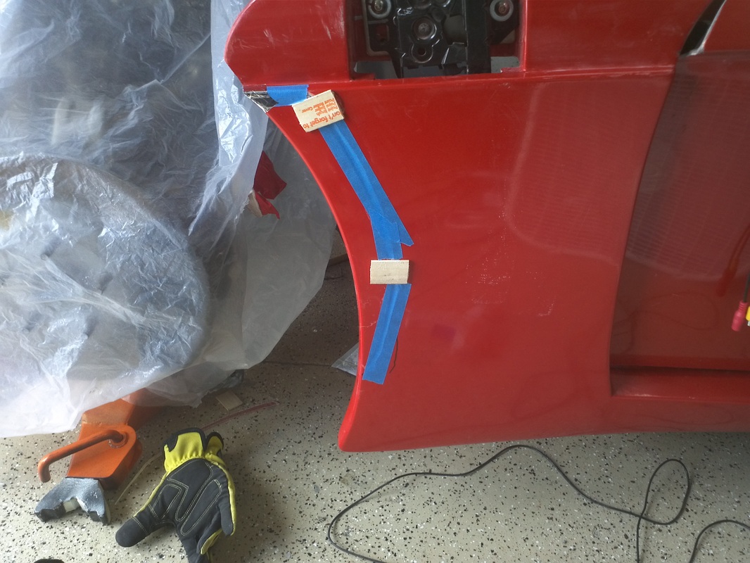
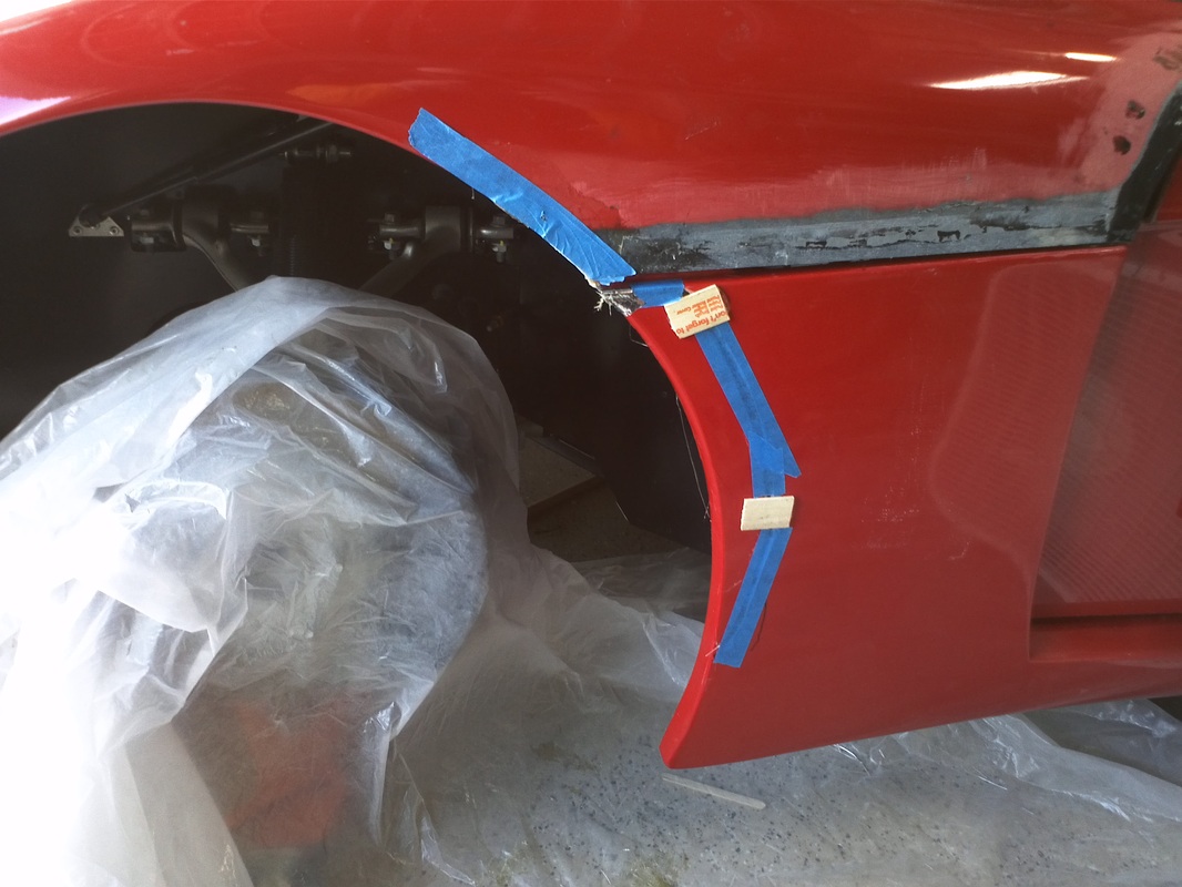
To rework this area I added fg to the hood portion to give it the same contour as the door. After doing this I was able to make, what is now, a 1/8" gap. I will finalize the gap here and on the driver's side once I have the driver's door to this point.
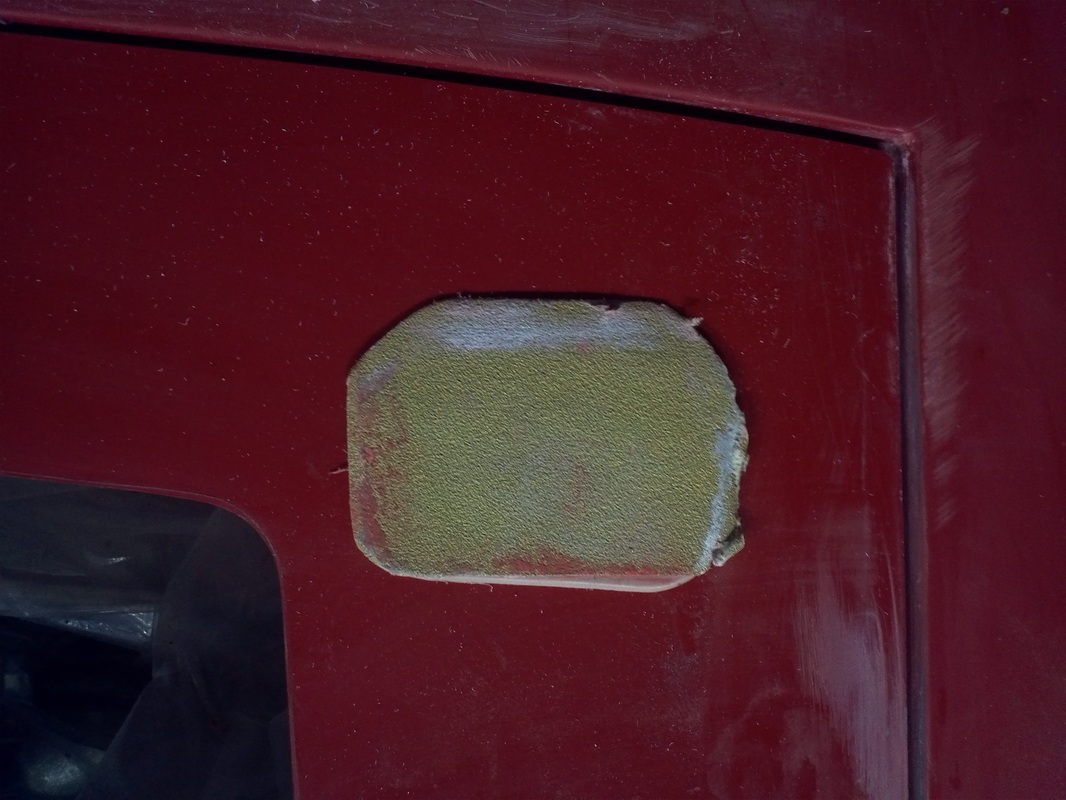
Filling the hood emblem recess was very straight forward. I cleaned and prepped the area, removing all of the gel coat in the recess and blocking the surrounding area. I filled the recess with fg then Rage.
Filling the hood emblem recess was very straight forward. I cleaned and prepped the area, removing all of the gel coat in the recess and blocking the surrounding area. I filled the recess with fg then Rage.
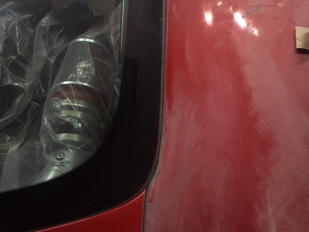
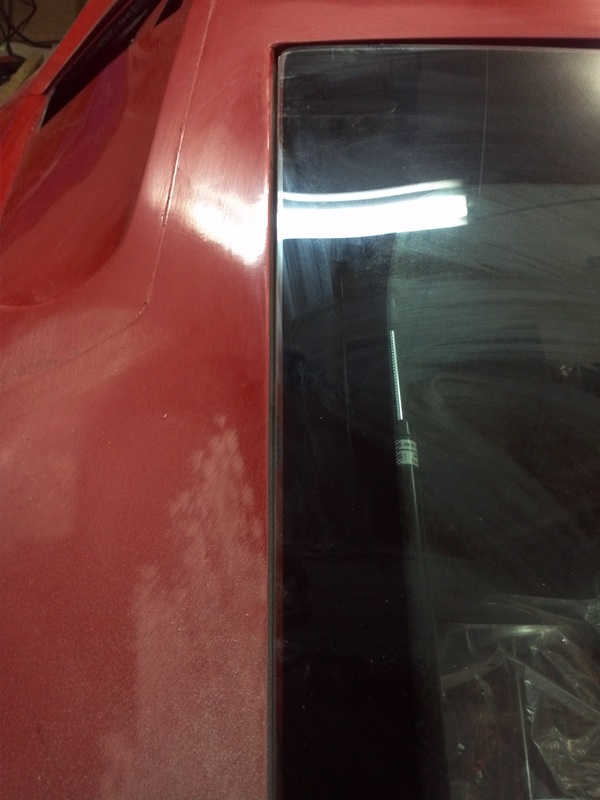
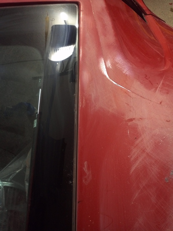
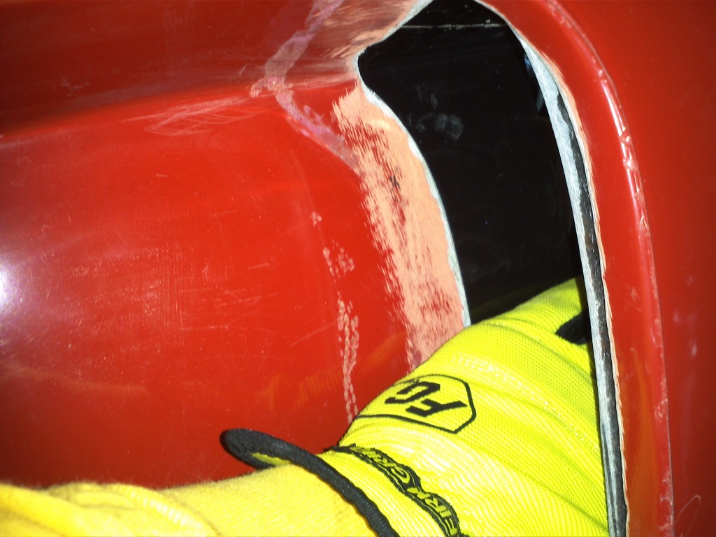
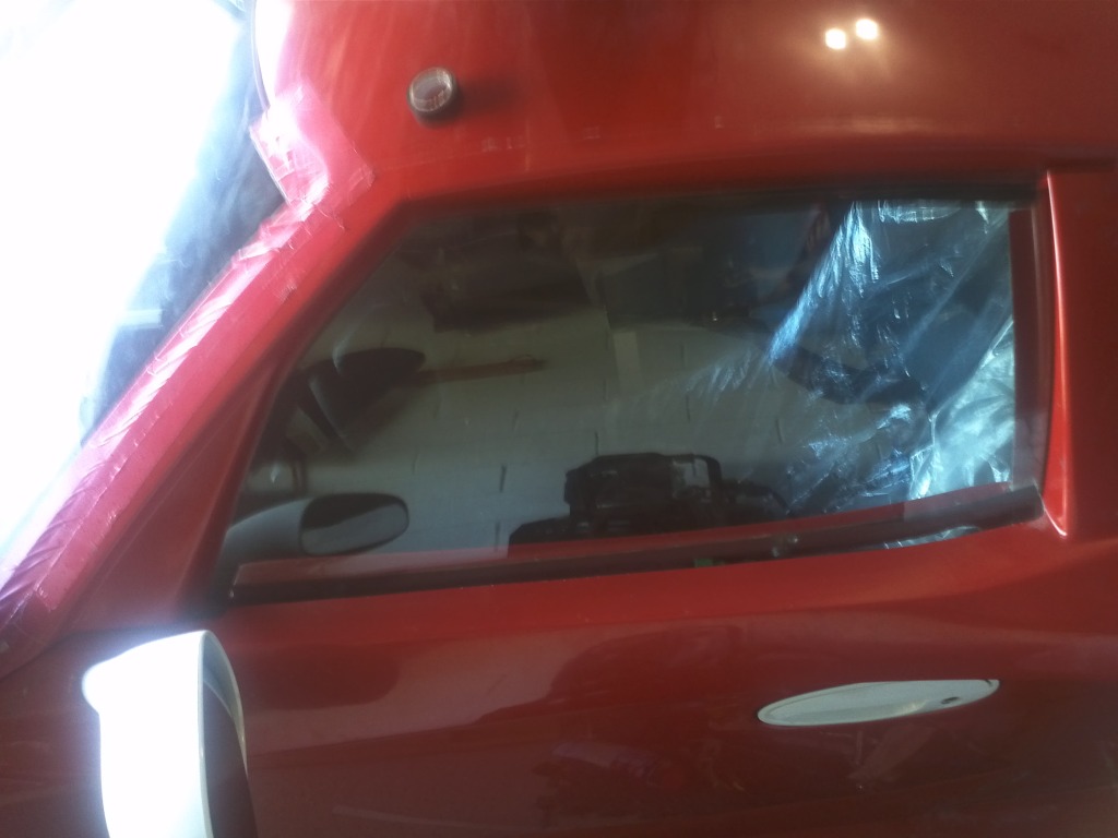
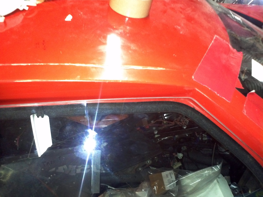
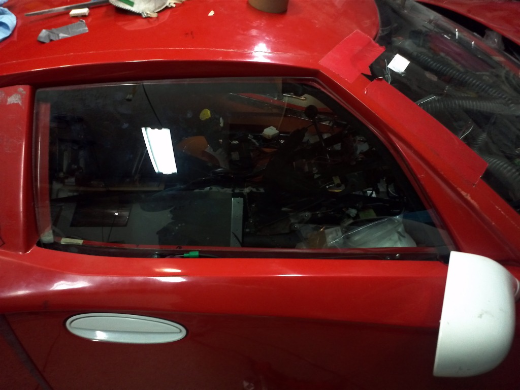
Quarter Window Reveal Fix
If you seen pictures of painted or completed GTMs with the rear quarter windows installed you've likely noticed that you can see the body through the window on the aft vertical. If the window is tinted it is less eye catching, My solution is simply removing the excess material.

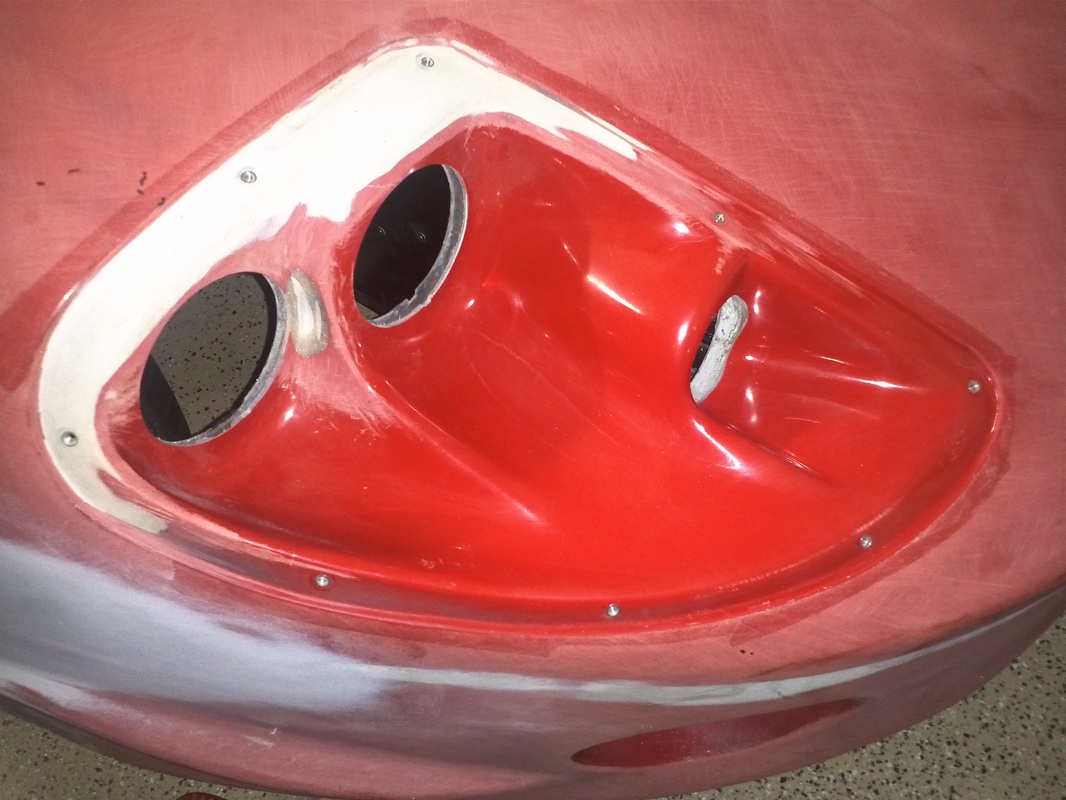
Parking light/turn signal headlight bucket work.
Hatch work
I worked the gap around the hatch. I had to remove the duct tape and it's residue, which was holding the window in place. I used a middle sized Body Filler Applicator with a strip of adhesive backed 80grit attached to one side to finalize the gaps after getting them close with sanding. I also removed about a half inch of material from the left inside of the glass area so that the reveal was the same. Prior to this you could see the hatch on the LH side on the inner edge of the glass. There were also voids between the inner and outer parts of the two pieces that are glued together to make the complete hatch. I filled all of them with 3m 8115 pane bonding epoxy to fill the voids.
Once I'm satisfied with the gap I will soften/round the edges.
Once I'm satisfied with the gap I will soften/round the edges.

Fiberglass Cloth Added in Preparation for Hatch Gap.
I added five layers of cloth to both inside lower hatch glass corner areas. These areas are close enough to the the hatch glass that I will risk sanding through the body when I gap the hatch. The cloth will alleviate this rick.

Reverse Light Mock Up
With the louvers in place I put the diffuser back on the GTM and placed the reverse lights on the top louver. Theses LED lights allow me to run all red tail lights. I still need to create a bracket for the lights. I also drilled the remaining holes (1/8" for now) that secure the diffuser to the body, and cleco'd it in place. These will be replaced by 3/16" black rivets after paint. I'll also get some better pictures this week.

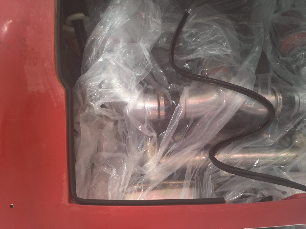
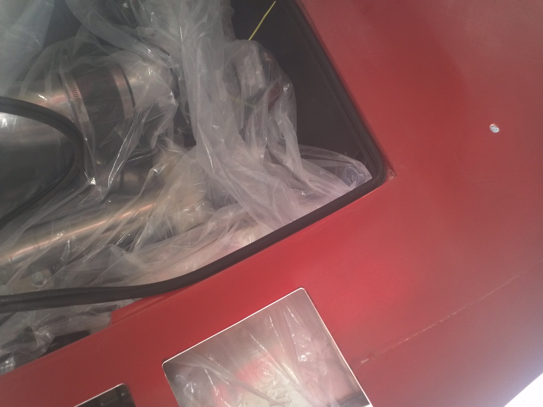
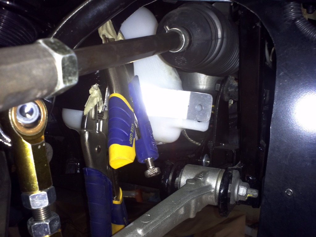
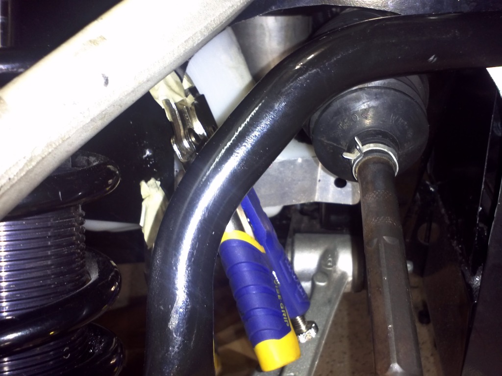
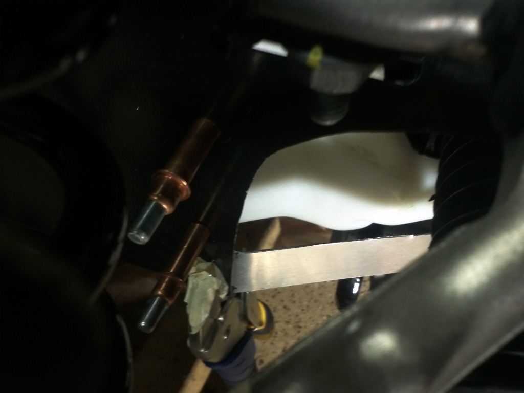
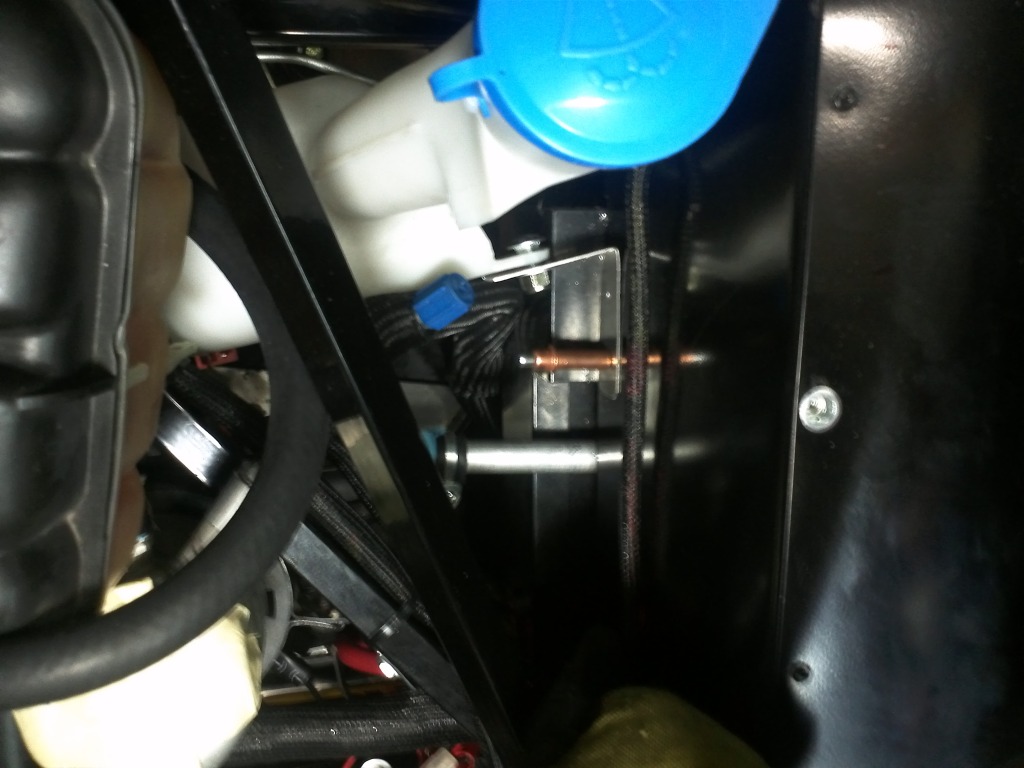
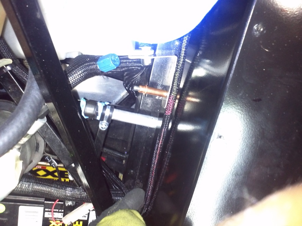
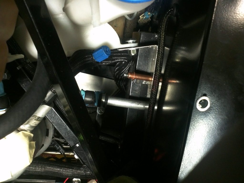
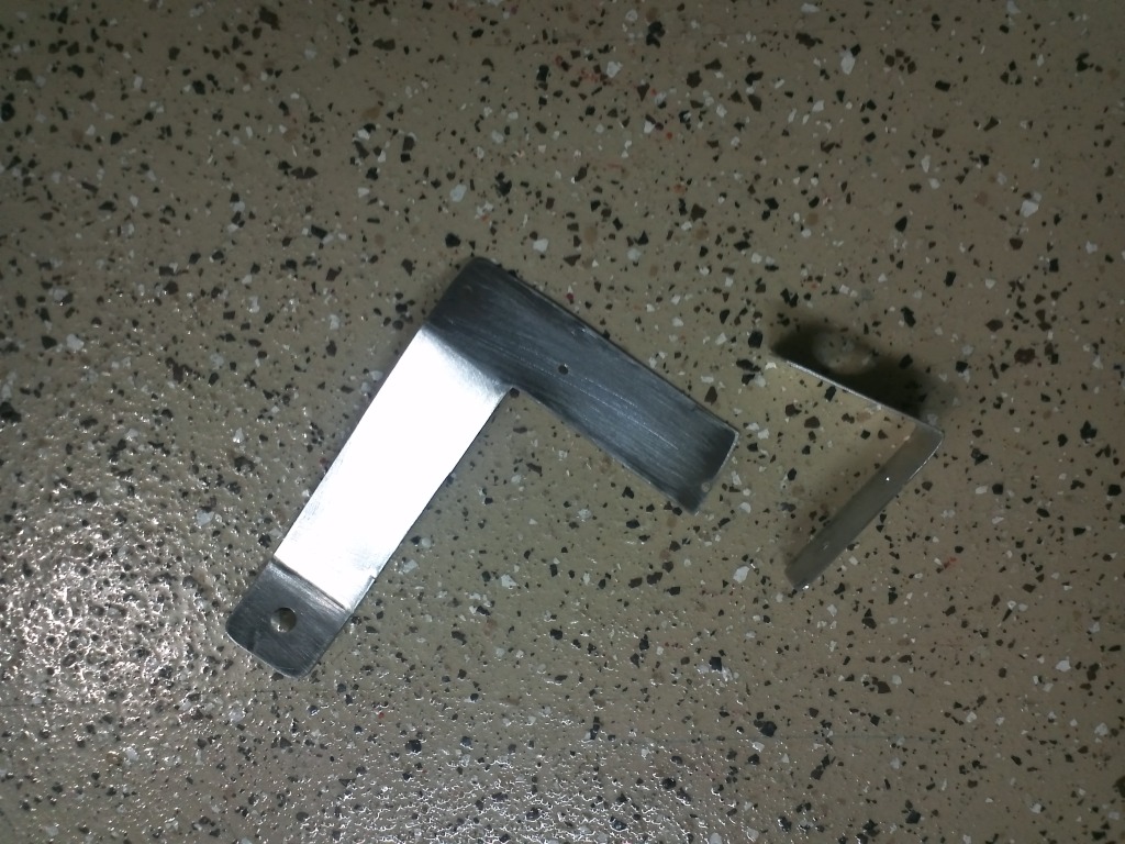
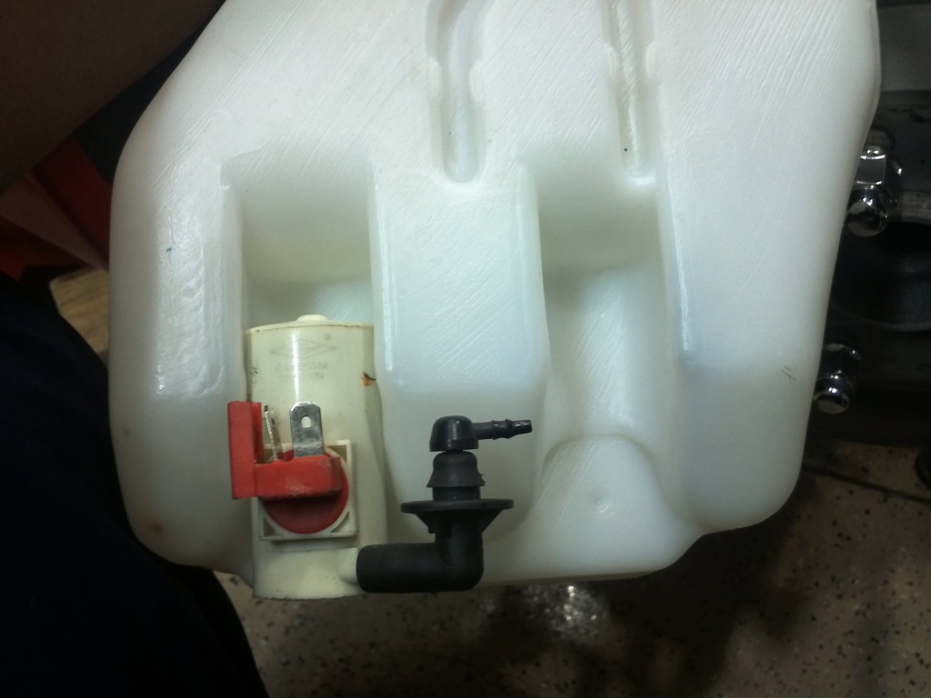
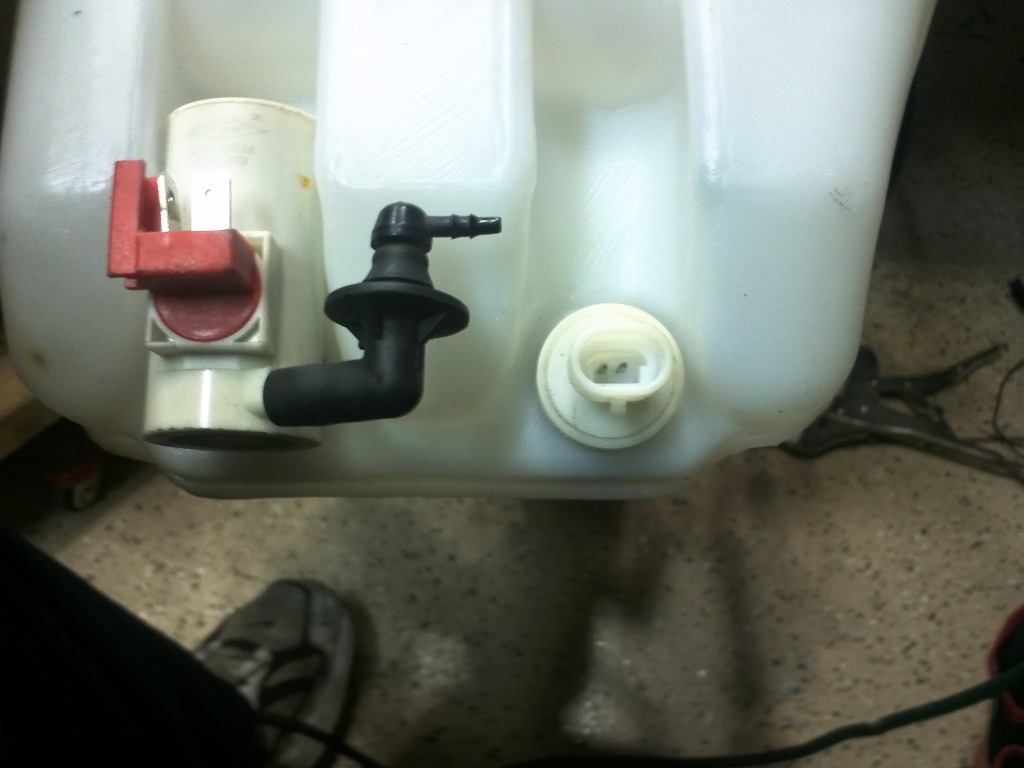
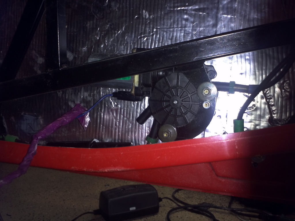
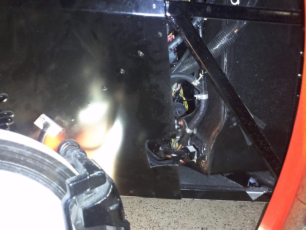
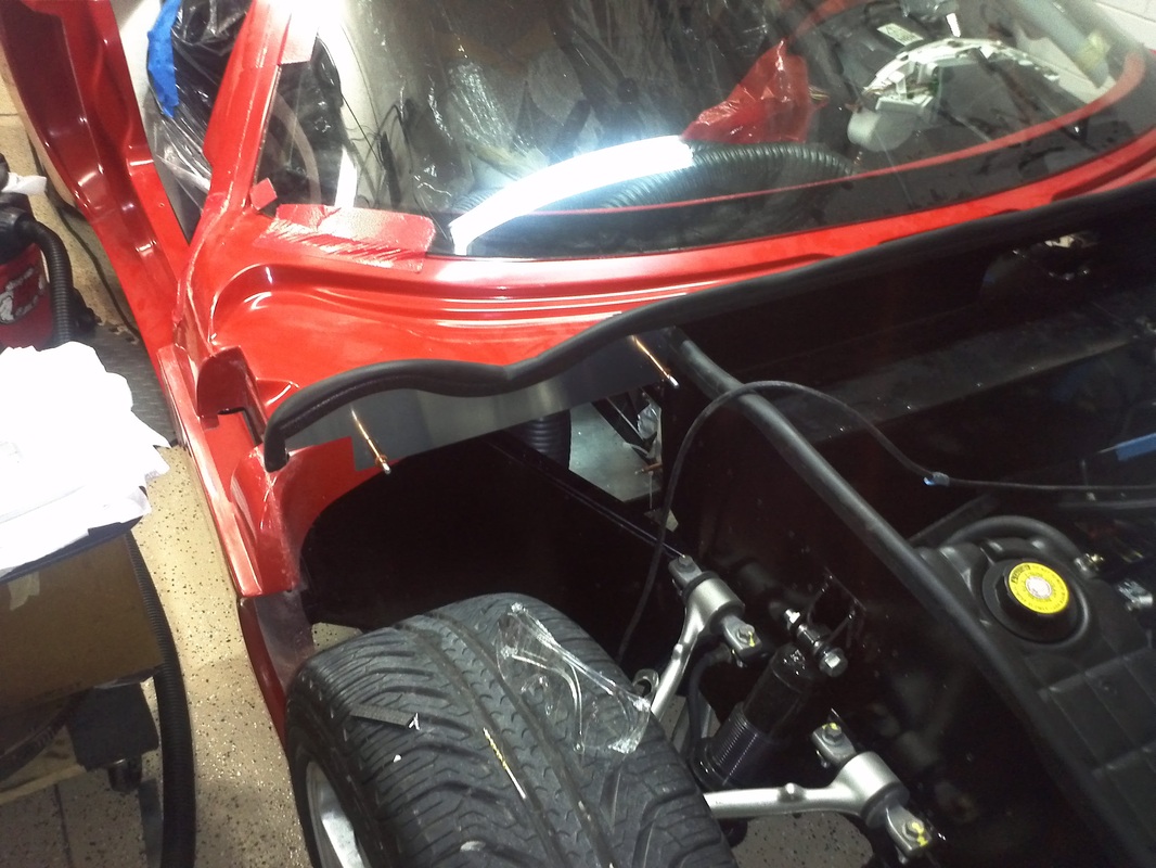
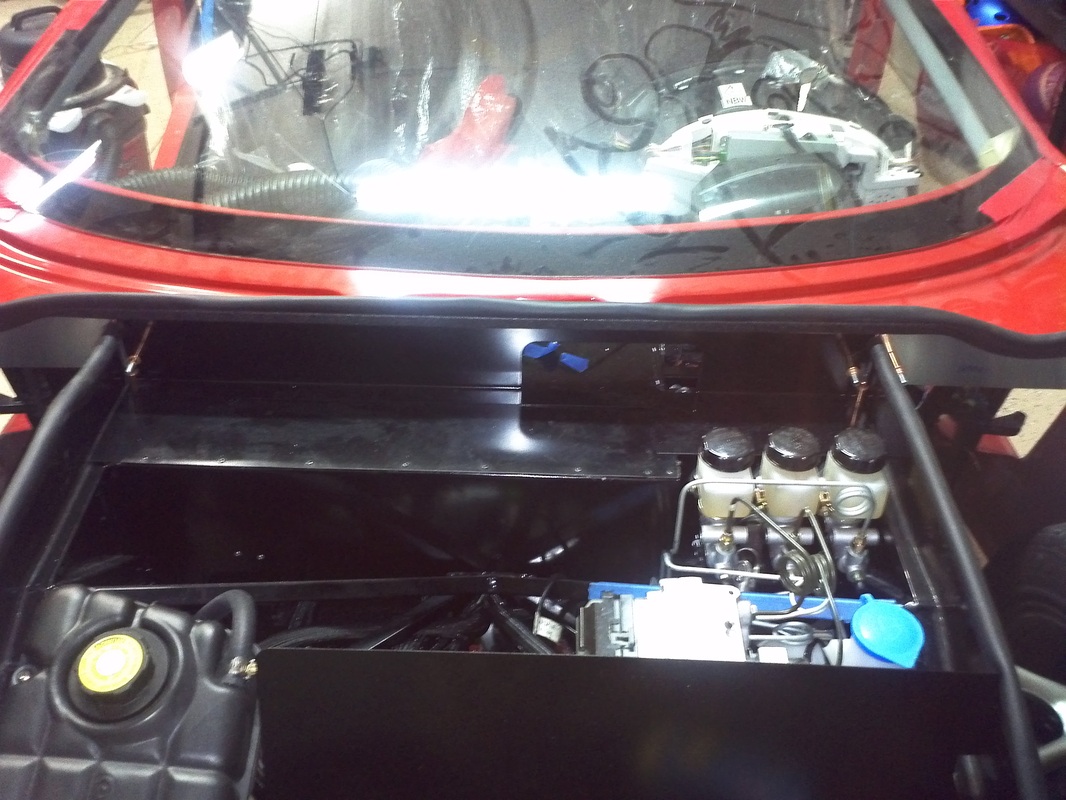
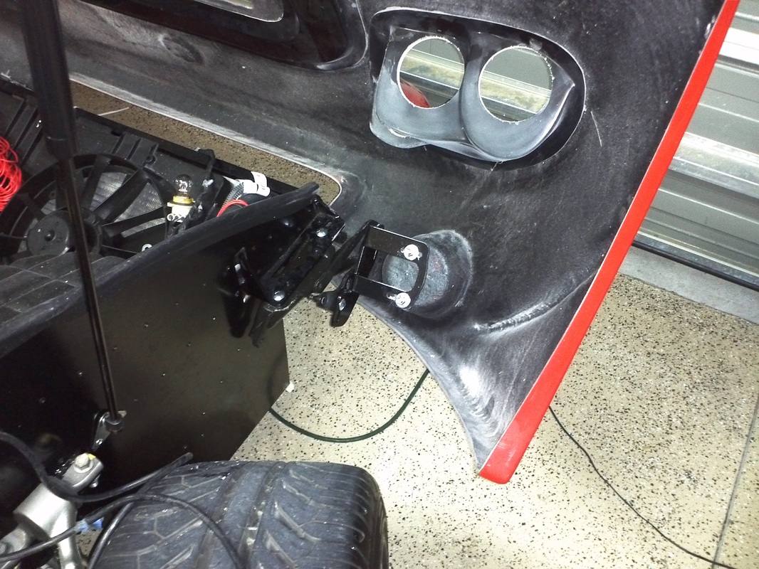
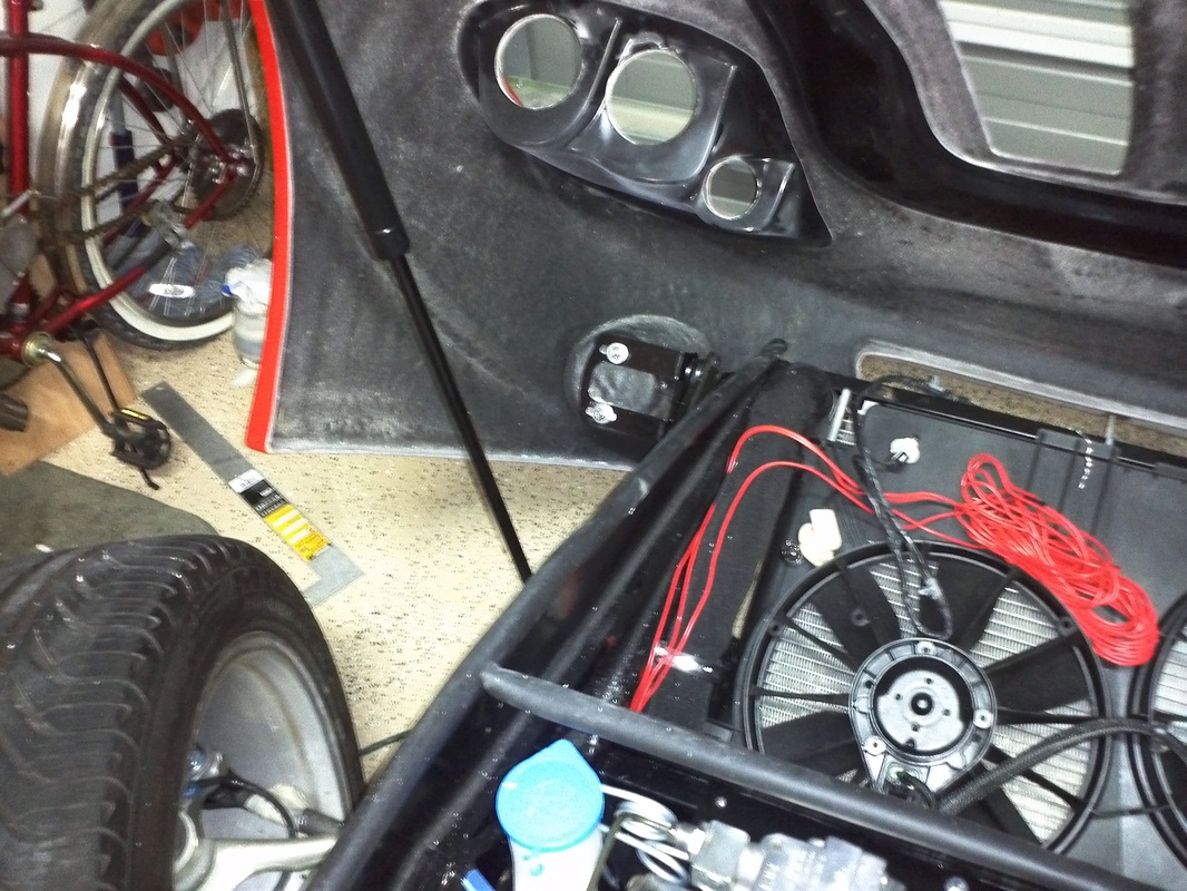
Washer Bottle Relocation and Low Fluid Indicator Install
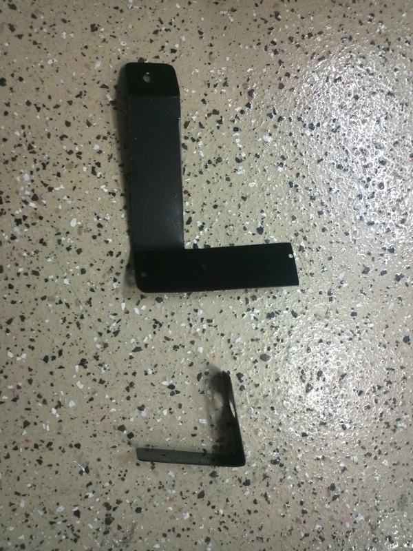
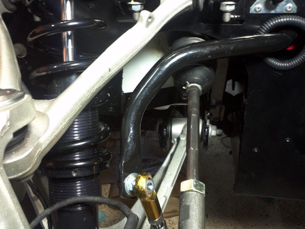
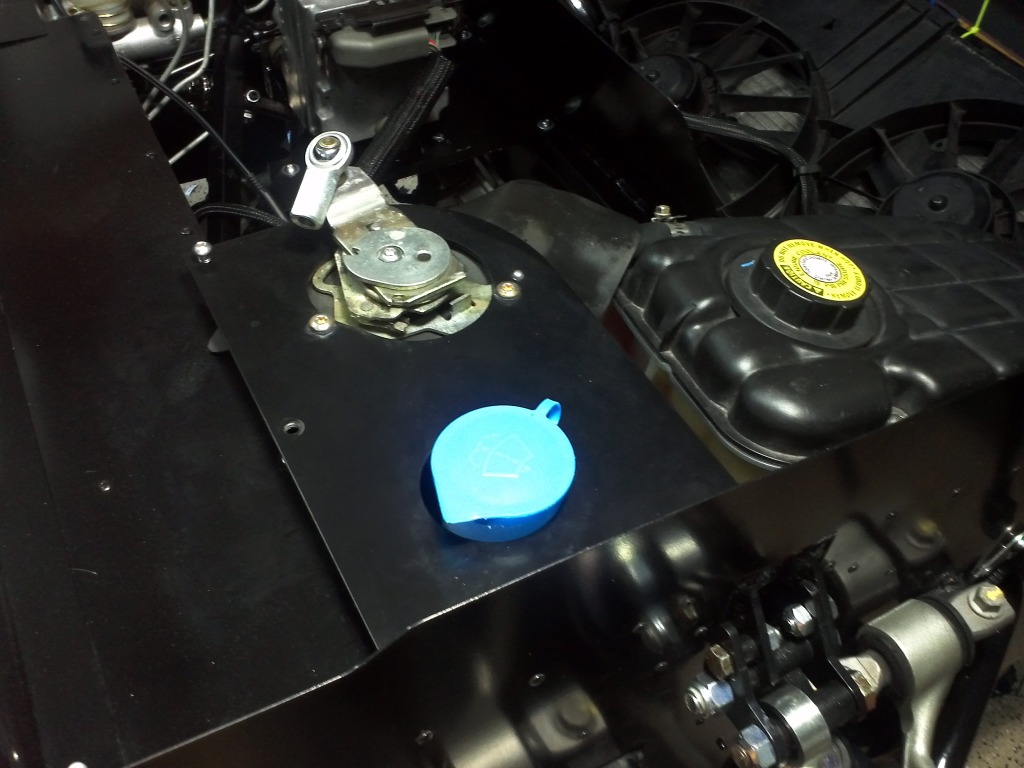
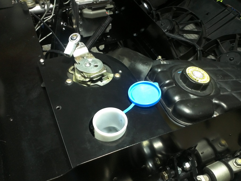
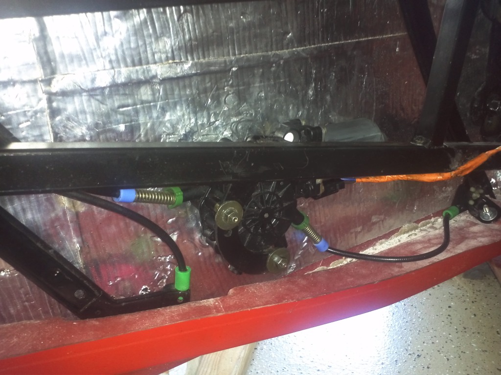
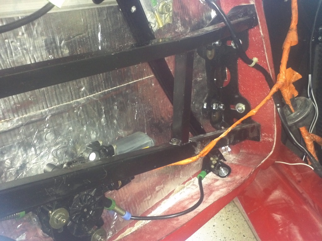
The washer bottle had to me moved from the LH side location. The steering linkage for the magnasteer rack needed some of that area. The windshield wiper mounting plate arrives with a hole opposite the motor opening. I made a couple of aluminum brackets, painted them black and mounted the washer tank on the LH side with it's filler protruding through the opening in the windshield wiper motor mounting plate.
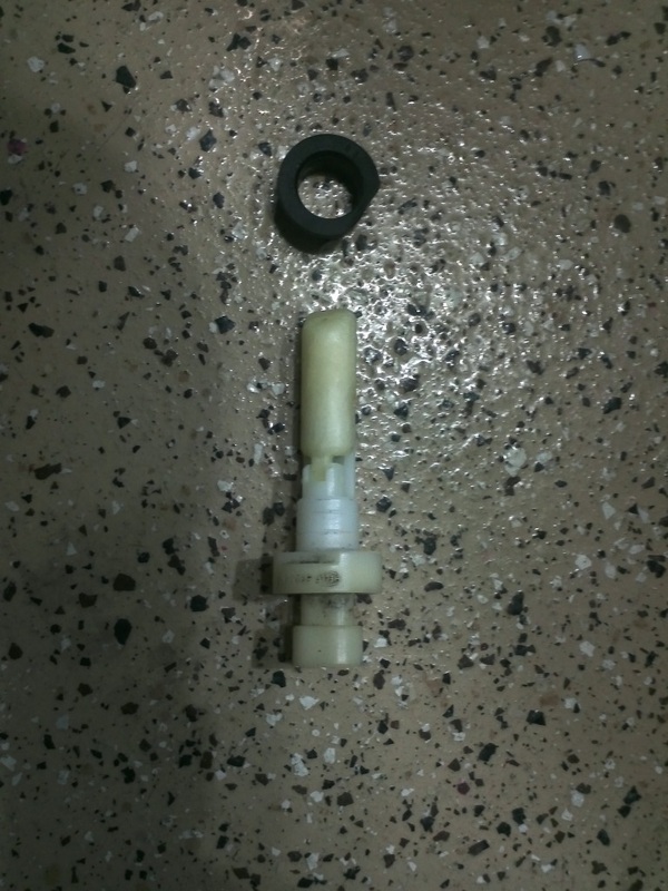
I also added the washer fluid low indicator from my donor to the washer bottle. The washer bottle has a reserved place for installing it. I drilled a 3/4" hole, added the rubber insert and then the indicator. I'll complete the wiring when I extend the washer motor wiring.
I also added the washer fluid low indicator from my donor to the washer bottle. The washer bottle has a reserved place for installing it. I drilled a 3/4" hole, added the rubber insert and then the indicator. I'll complete the wiring when I extend the washer motor wiring.


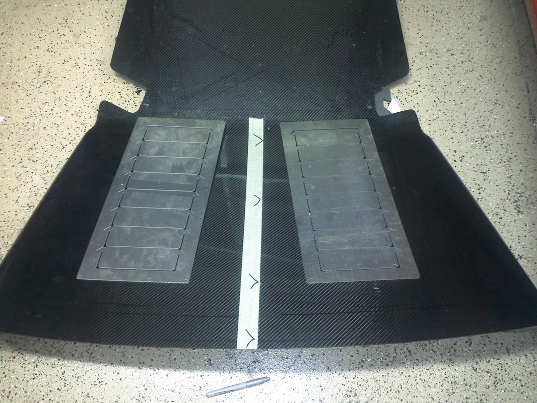
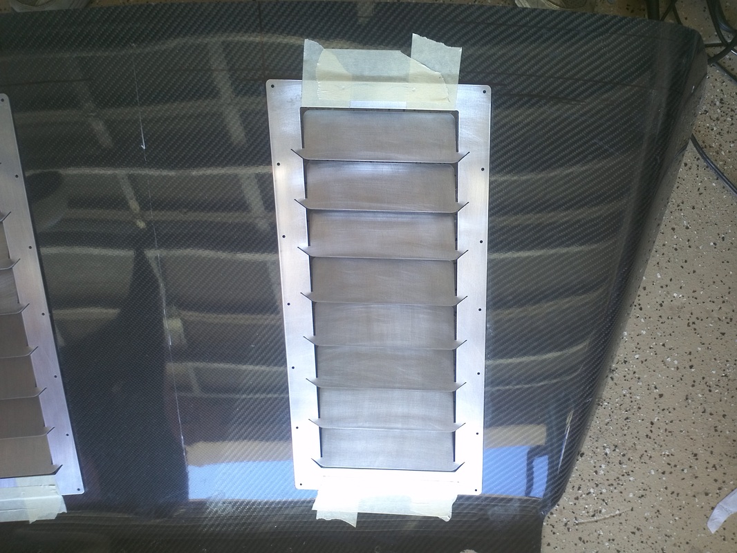
Diffuser Louver Installation Mock-Up
I was able to spend a few hours in the garage this evening so I decided to start the mock-up install of the diffuser louvers. These are Shane's 2nd version diffuser louvers. I like the way this version looks in conjunction with the strakes so I decided to go with the v2. I traced the outline of the body onto the interior side of the diffuser and marked it's center prior to removing it from the GTM. I positioned the louvers at 5" and parallel to the center line. I then positioned the louvers, taped them in place and scribed the area that will be cut out. Once I cut the area out I will clean up the louvers and then bend each louver to it's finished angle. From there the louvers will be ready for my next powder coat run. The same holes that hold the louvers in will secure the stakes also.

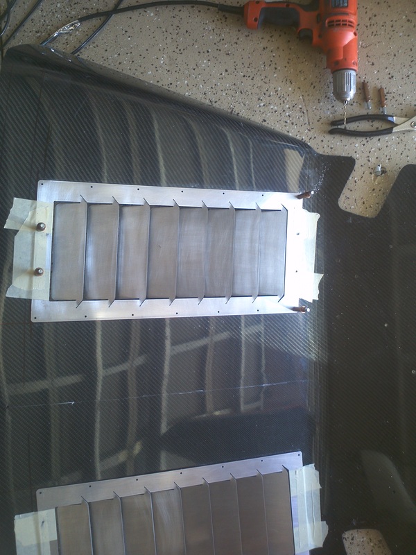
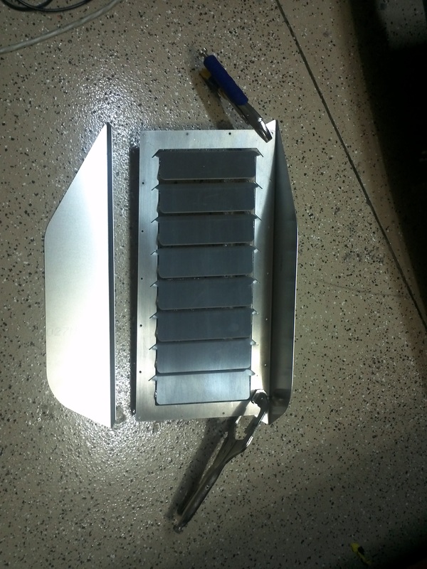
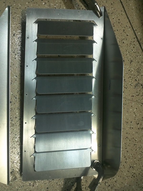
I found a few hours this afternoon to work on the louver
mock up. I cut the scribed holes with my jigsaw and squared the edges with
80grit. The louvers have been sitting on a garage shelf for over a year now so
I cleaned them up with 400grit and alcohol. I then made the initial louver
bends and sat them into the opening. I taped, drilled and then cleco'd them in
few places and drilled all of the 1/8" holes. In order to ensure the
strakes, which I’m not sure if I will run or not, were installed square to the louver
I drilled their holes with the louvers out of the diffuser. I positioned each
strake and clamped it in place. Then I grilled the two exterior holes and
cleco'd them together. Then I drilled the remaining holes. I then cleco'd the
parts onto the diffuser. The strake bends are not square and need to be squared
prior to powder coating. I will mount the diffuser and make the final louver
bend adjustments. Then the parts will come off so I can prep them for my next
powder coat run.


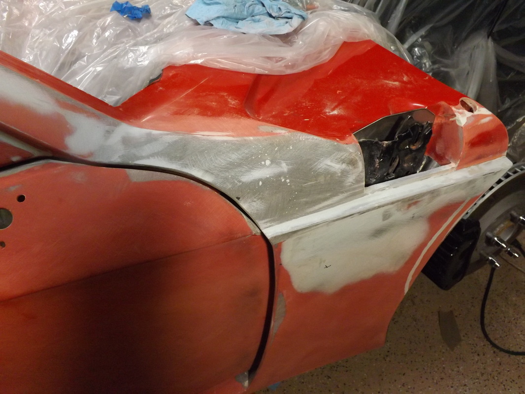
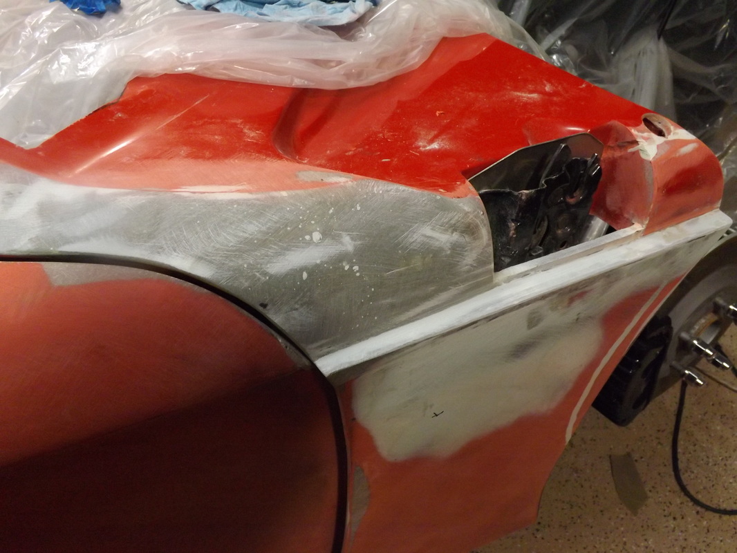
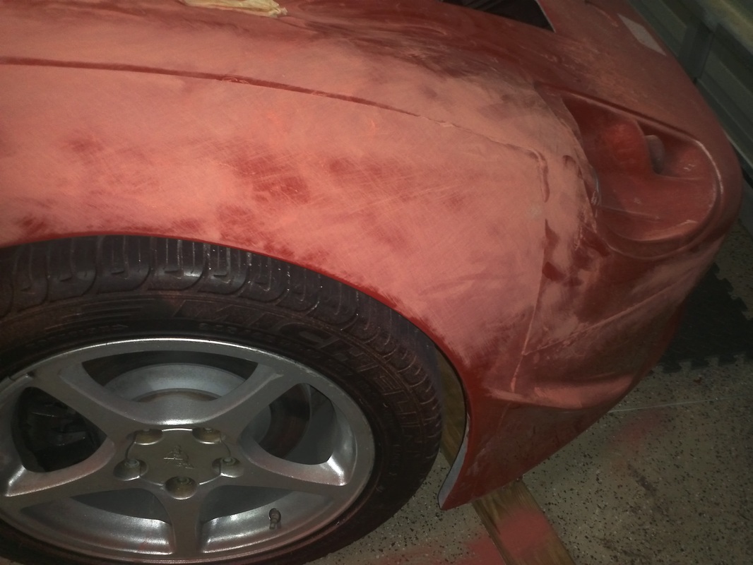
Driver's Front Wheel Well Re-Work
More Body Work. Reshaping the wheel arc.

Driver's Door A Pillar Rework
Lower horizontal of pillar required a 1/4" of material to be removed in order to get the door adjusted into a position that allowed the door and the area in front of the upper door to line up for a flat finish. I reworked the area with 8115.


Blocked Down the Mold Lines Over Rear Wheels.

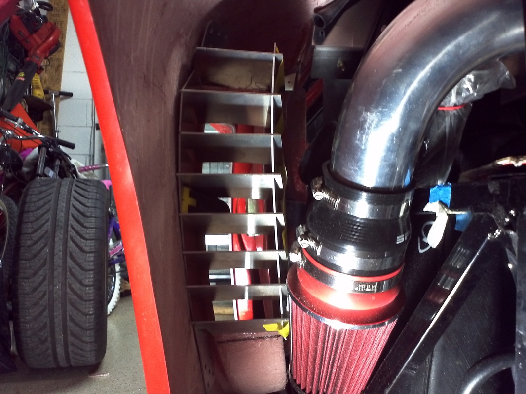
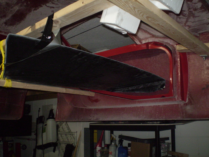
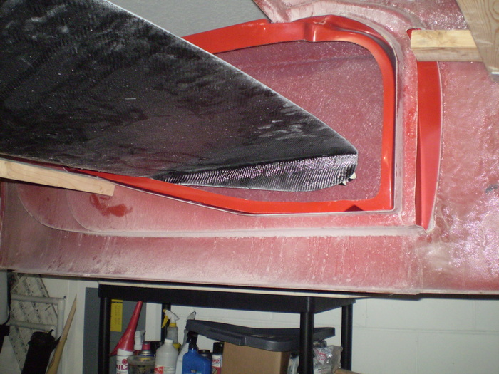
Thomas#142 Full Side Air Intake Scoops.
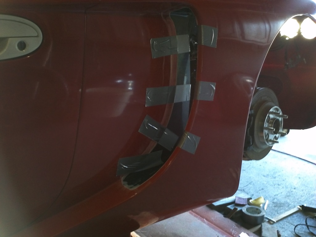
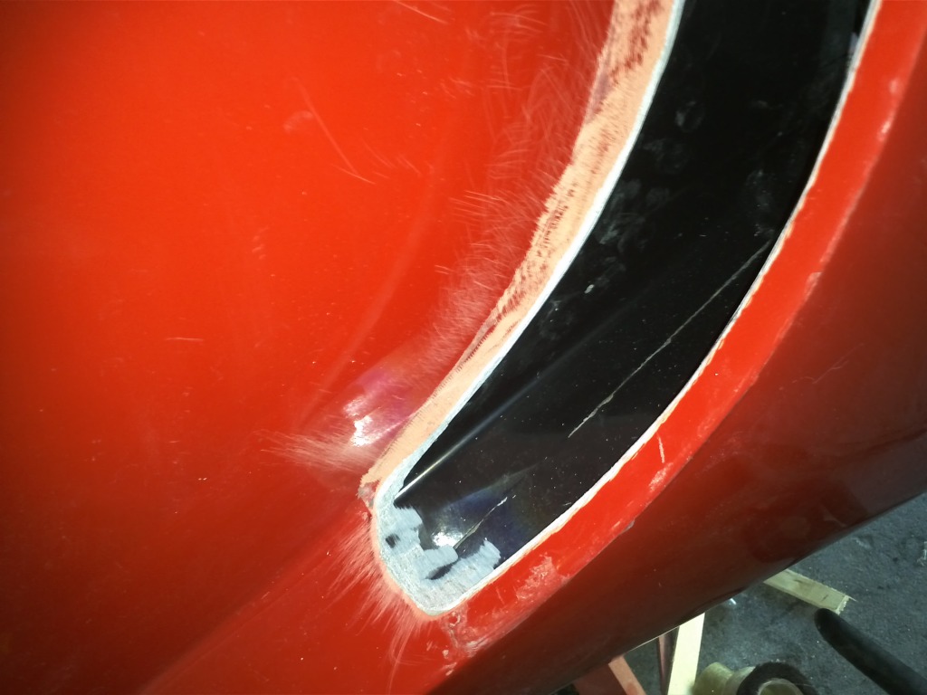
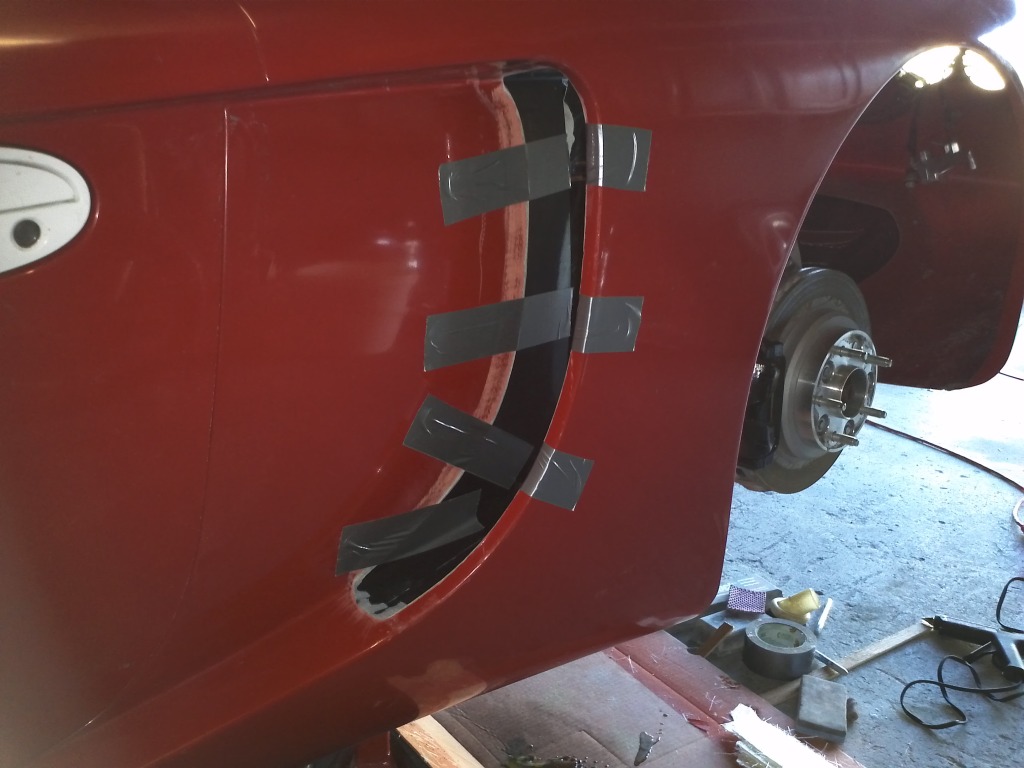
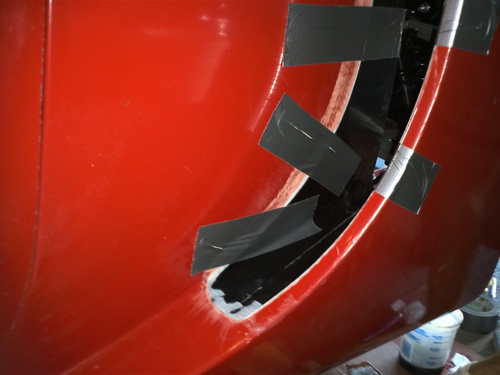
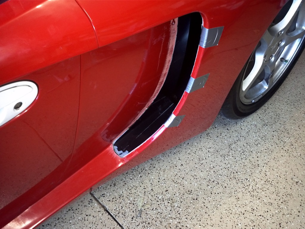
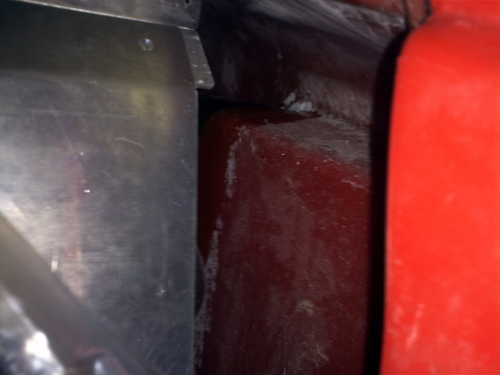
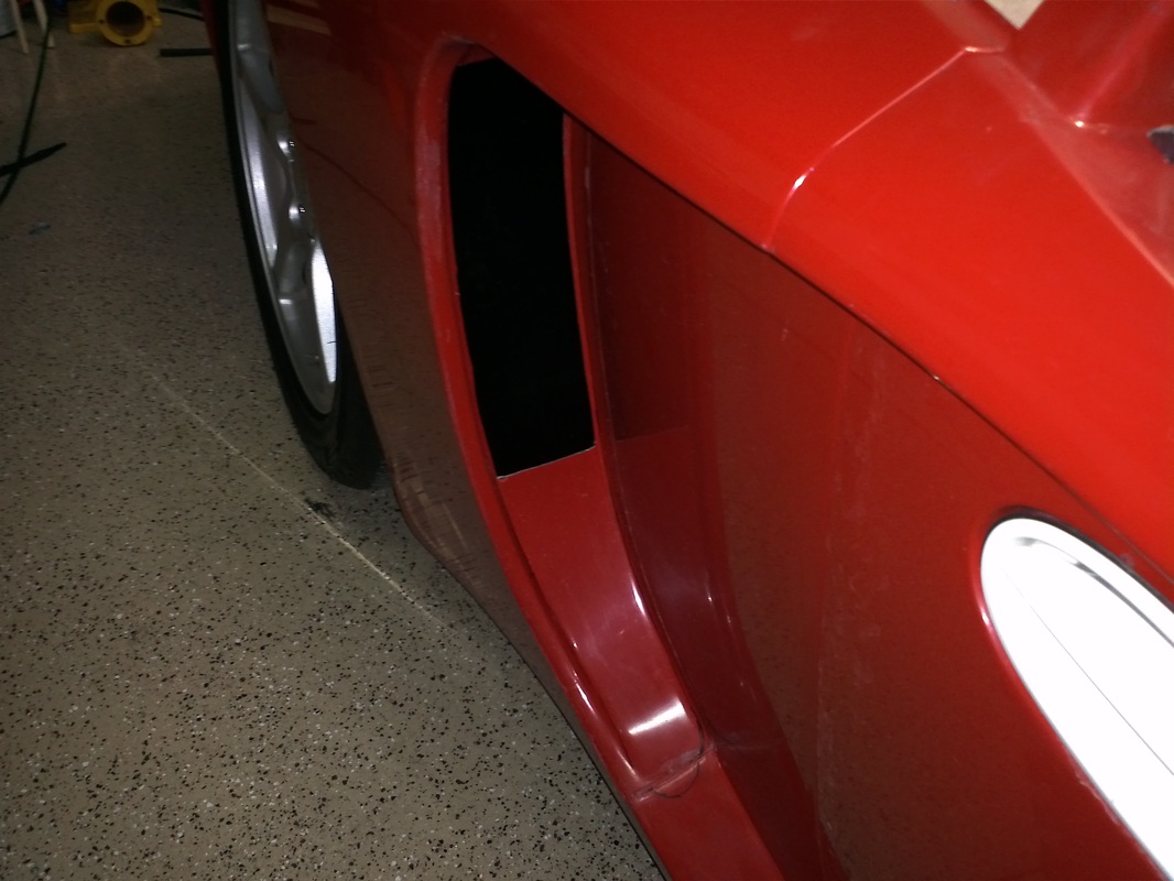
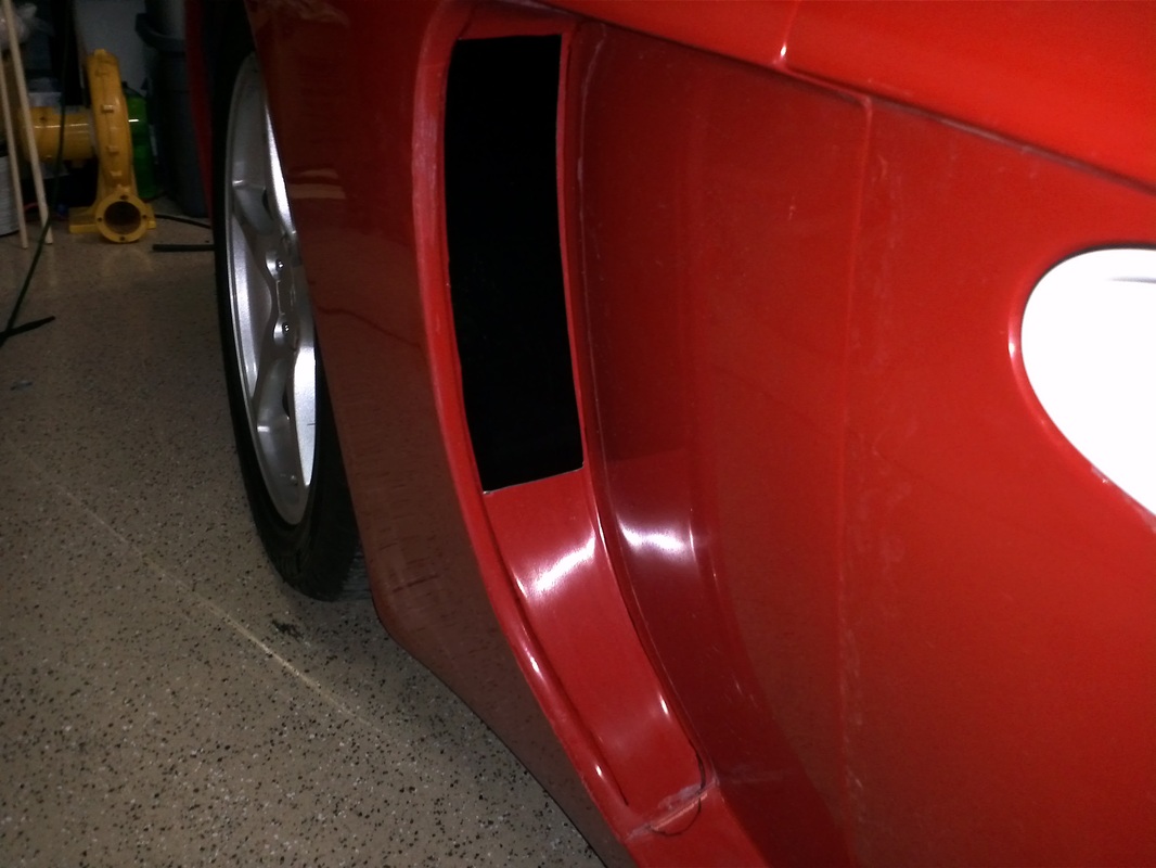
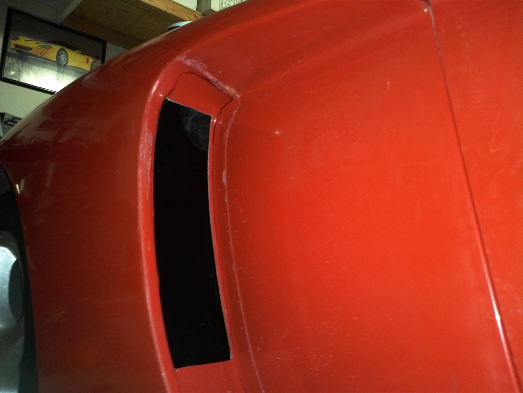
After seeing the full side scoop on Tom's GTM and the standard opening in my GTM side by side my opening looked inadequate and out of place. I was fortunate in that Tom let me help make my side scoops. His plug is unique and works very well in producing the side scoops. I can't take the credit for the clean installation of the driver's side scoop. I assisted Tom with it which allowed me to take in his technique for installing them. If you've seen his scoops installed on other GTMs I'm sure you will see a huge difference here with his technique. He created the part, right. We started by cutting the opening just undersized on the to verticals and short on the top and bottom horizontals. Then we sanded the opening's horizontal edges until there was an almost gap-less butting of the scoop to the body. Then we traced and slowly worked the top and bottom horizontal edges of the body until the top was a good butt and the bottom made a wedge under the body's edge. The sanding and fitting was done so well that we only needed duct tape and a spacer to hold the scoop in place for glassing. Then we saturated strips of fg mat and laid them along the inside about the perimeter of the scoop.
I plan to install the passenger side scoop this weekend without assistance.
I plan to install the passenger side scoop this weekend without assistance.


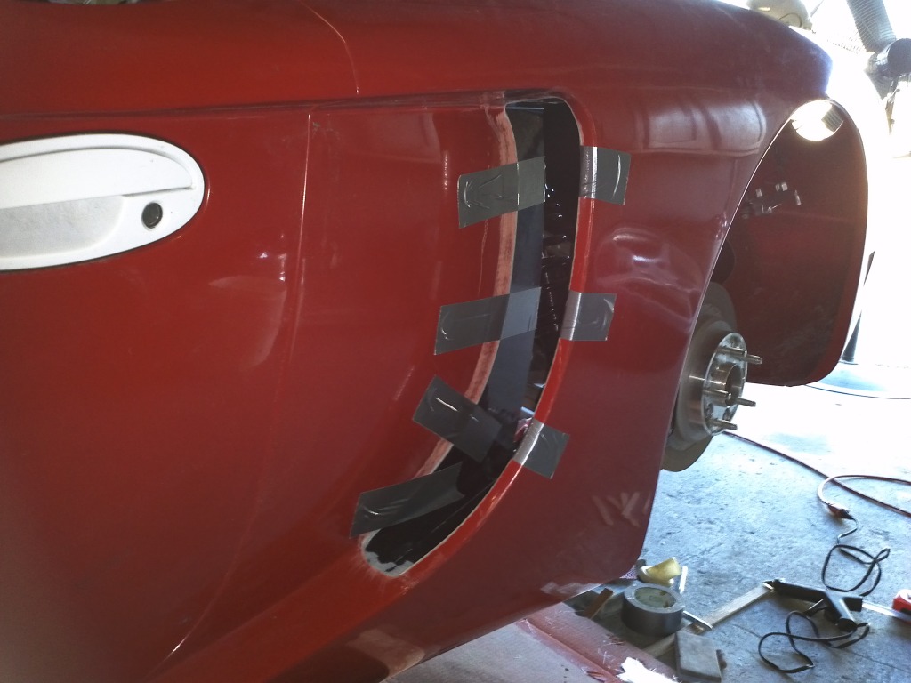


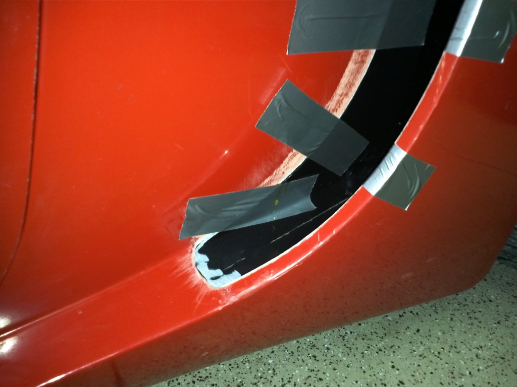
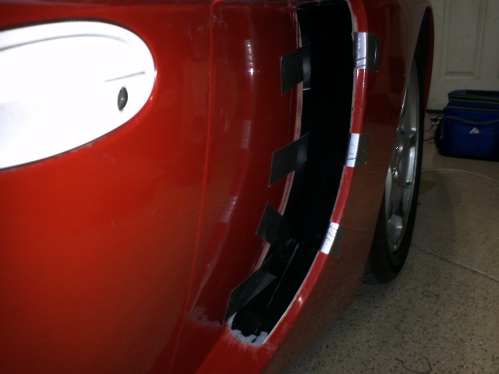
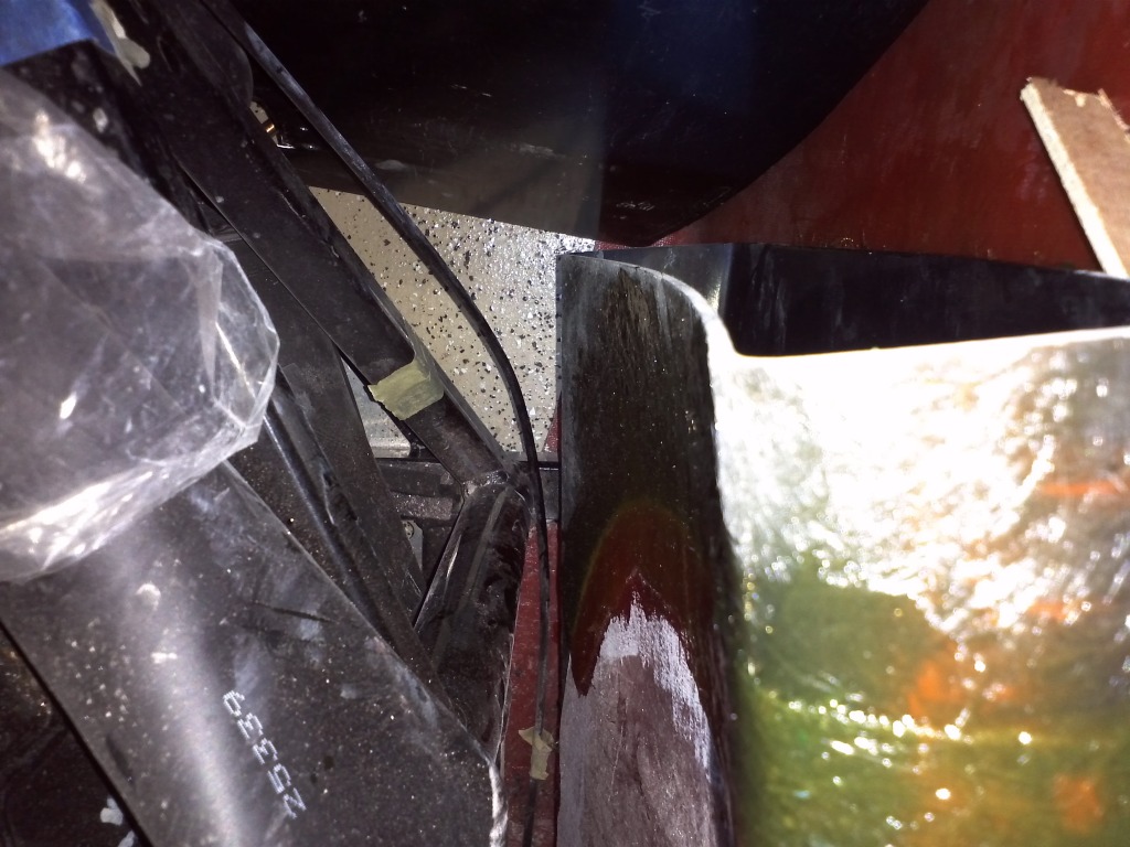
Passenger Side Install
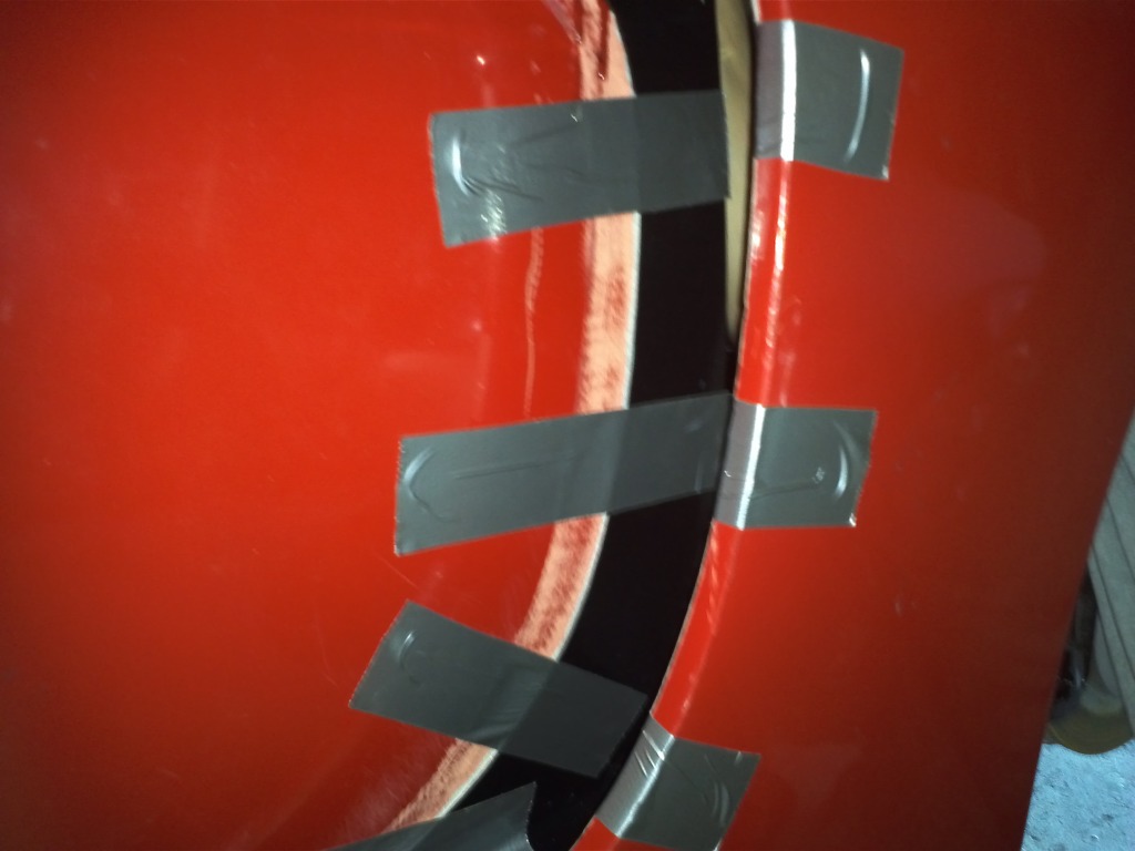
I followed Tom's Techniques to get a really good fit. I came close only needing a block (that I cut from a 1x2) and shim for fine tuning, to get the inner panels exactly where I need ed them. I put hot glue on the black and shim to ensure it stays in place. I used the shim and strips of duck tape to hold the scoop. I prepped the fg mat by cutting some strips. I'll glass it in tomorrow.


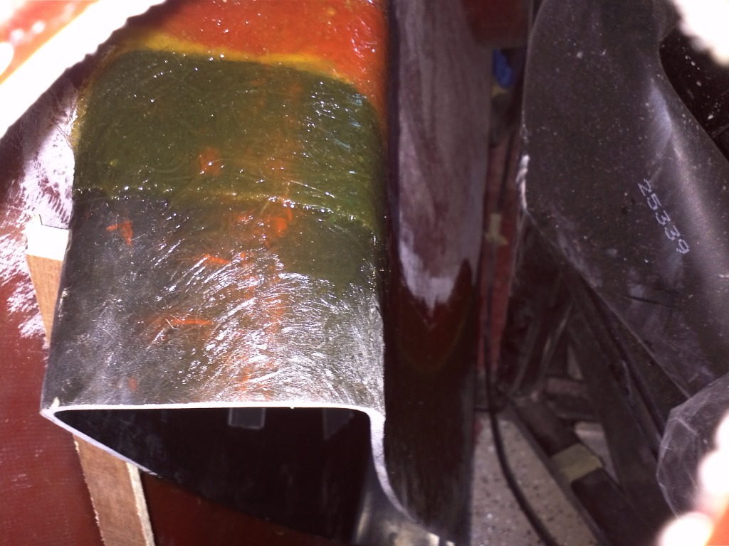
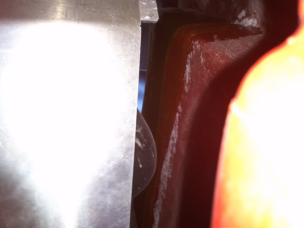
Passenger Side Fiber Glassing
The Fiber glass mat was cut into rectangles. I mixed the resin and saturated the strips before laying them in place. Both side will be finished when the body comes off.


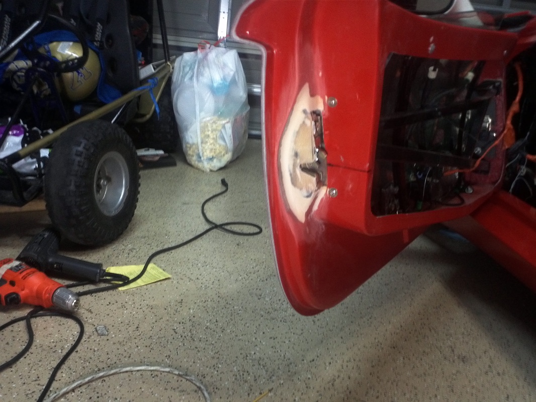
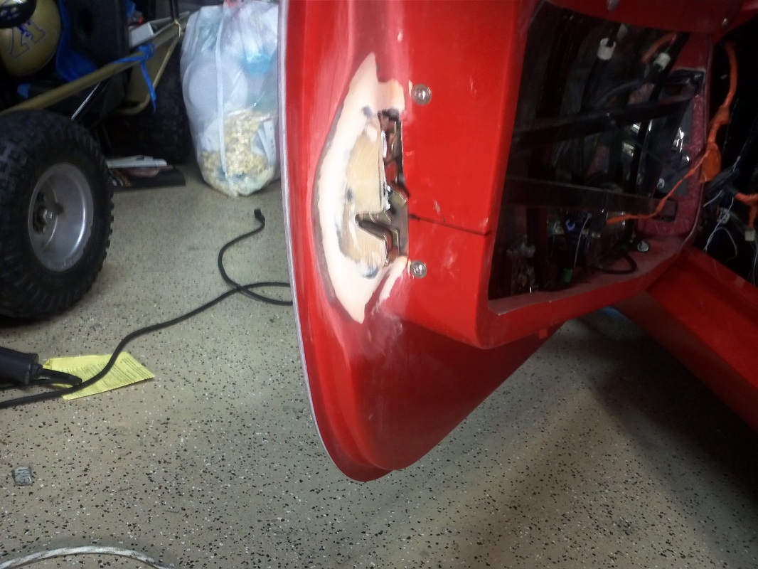
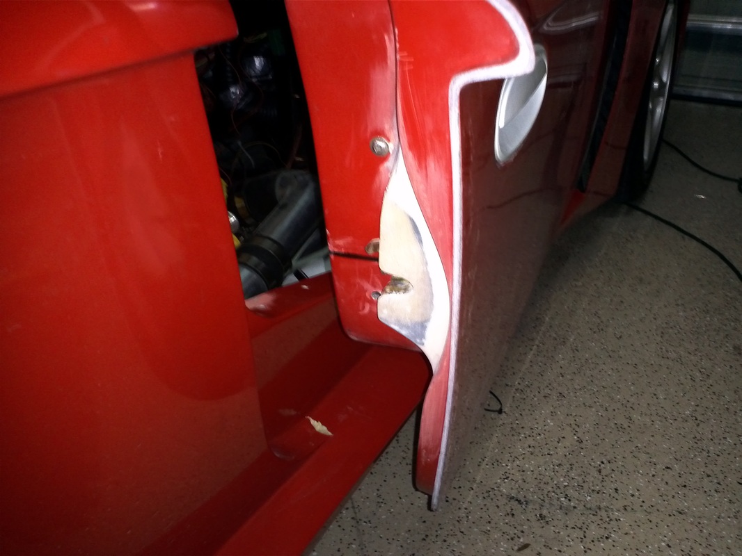
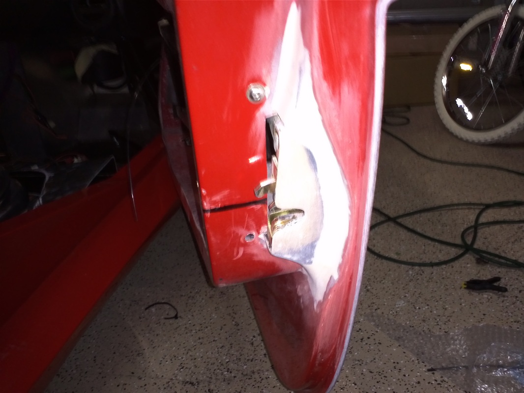
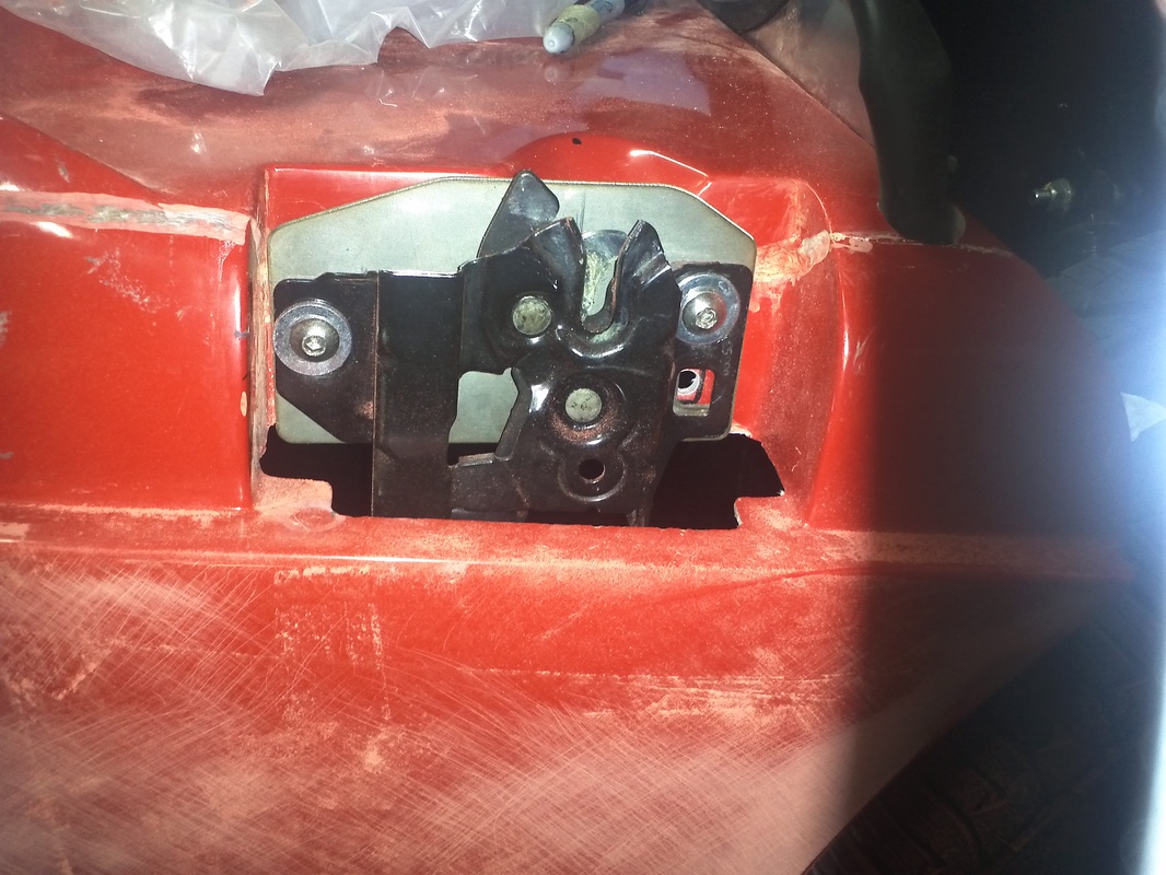
Enclosing the Door Latches
Tom and I did the initial work on fiber glassing in the door latches. I still need to pull them and take care of the areas where I initially removed too much material and add a front above and below the moving latch. I also need to paint the latches black.

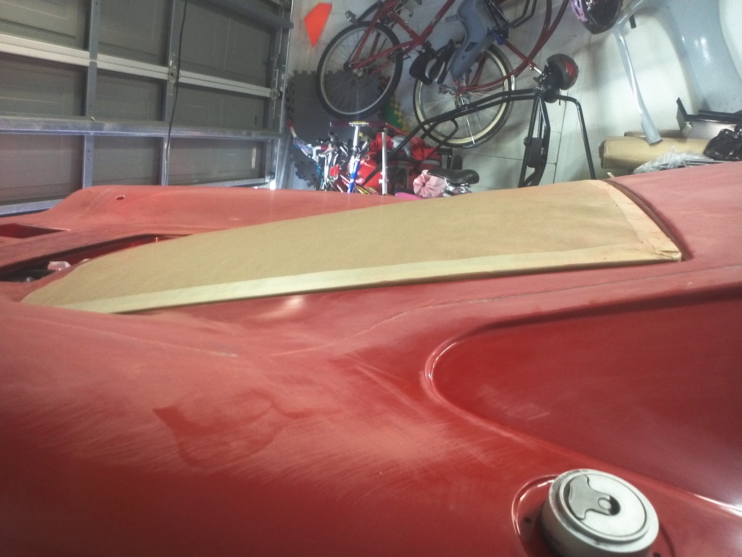
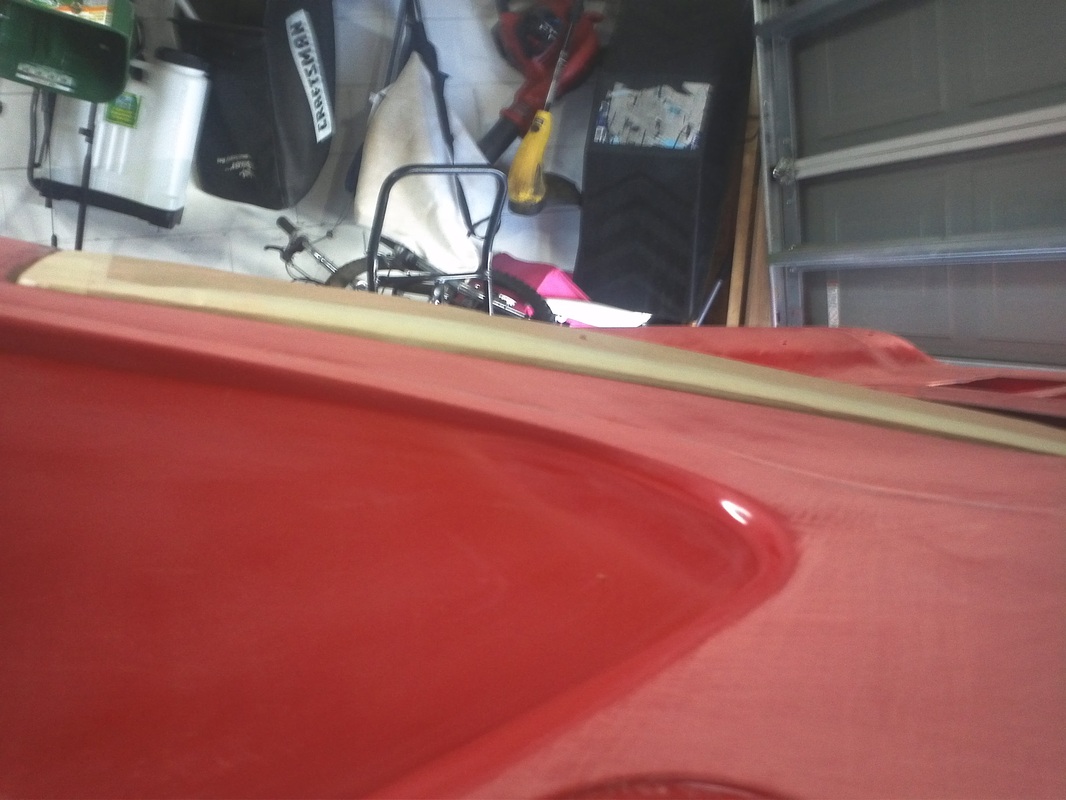
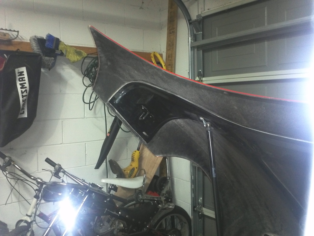
Hood Adjusted and Material Added
All of the nuts of the hinge were loosened to allow for the adjustment of the hood. Referencing where it was prior, the front has been raised and the entire hood moved aft. The RH side of the hood's horizontal in the latch area lines up well and has about a 1/8" gap so it is ready for final gapping. The LH side was a different and had a 1/2" gap. I used a technique and a pre-glassed sheet of material I received from Tom (Thomas#142) for this body work. Tom is a wizard with composites, molds and general work in this area. He's also just over a 90 minute drive away. His window area air scoop is by far the best looking scoop and you will find it on many GTMs. I sanded the gel coat from the outside and the sanded the inside in preparation. I used 8115 and bonded a strip of the pre glassed sheet to the inside with a 1/2" reveal. Then two additional pieces were bonded to the reveal to build the thickness. The fore and aft still need to be formed.
Door Adjustment
The doors have been adjusted. Referencing their original position each has been moved up and aft. The strikers have also been changed front the set I fabricated to a set of ½” GM latches purchased from the local auto parts store help section. The latches were perfect with the exception of their head thickness. Tom turned them on his lathe to decease the thickness of the heads. The door now shut with a finger push into a perfectly aligned position. Now I can address the windows again from the doors new position.
Driver's Side Window
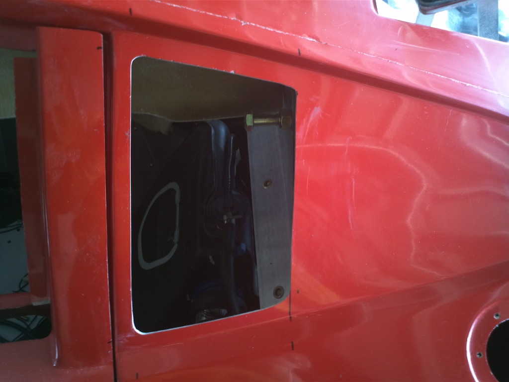
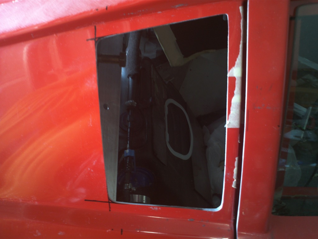
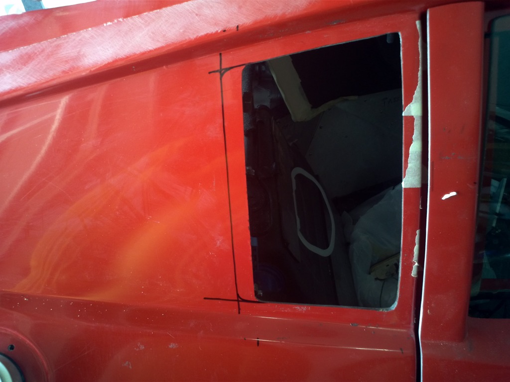
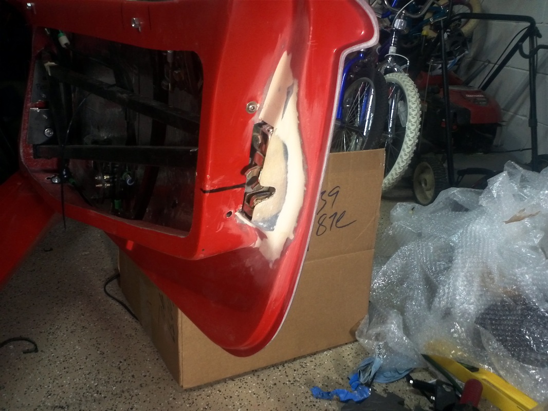
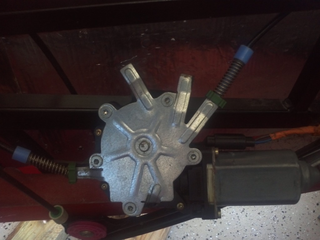
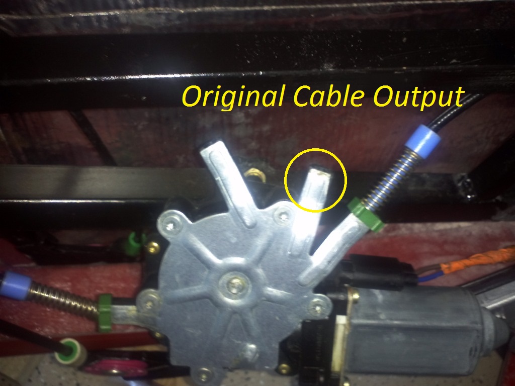
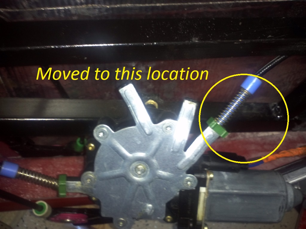
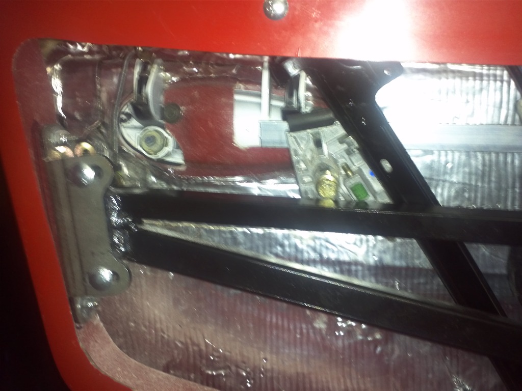
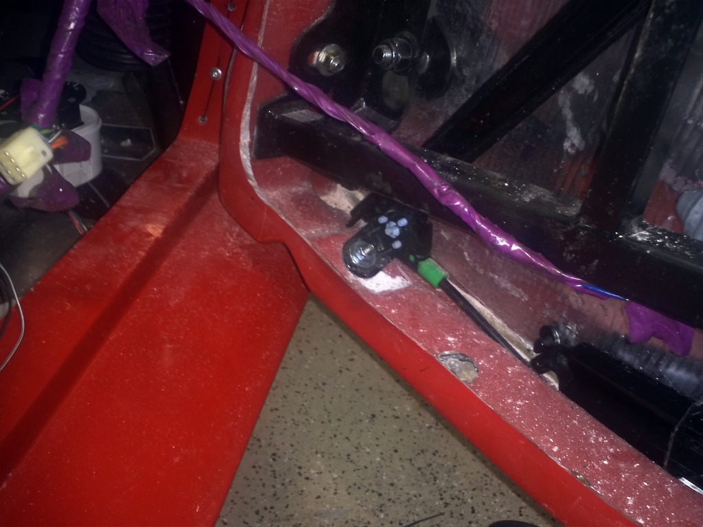
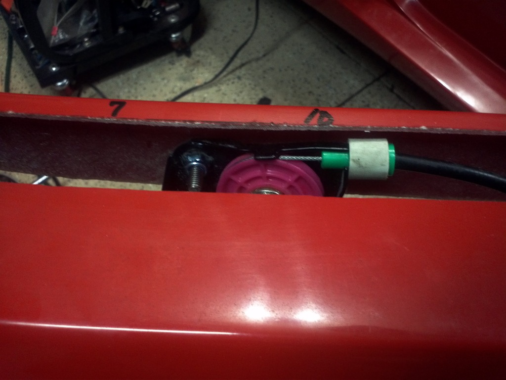
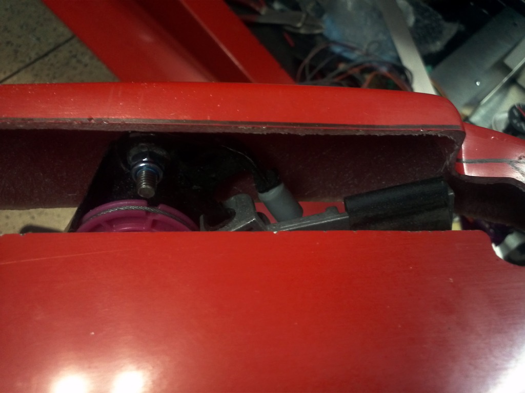
I decided to start with the passenger side anticipating that it would be the most difficult. I started work on the driver's side thinking it would go quickly and smoothly, but this wan not the case. For some reason, I suspect this door frame differs from the other, the regulator motor lower cable output is directed straight down. This was not allowing the cable to move the clamps up and down smoothly. To solve this I removed the plate covering the cable. I then moved the lower output cable to the next location, giving the output a less resistant path. I also moved the motor's termination to the opposite side in an effort to allow the window to go lower when in the down position this idea came from Rumrunner.
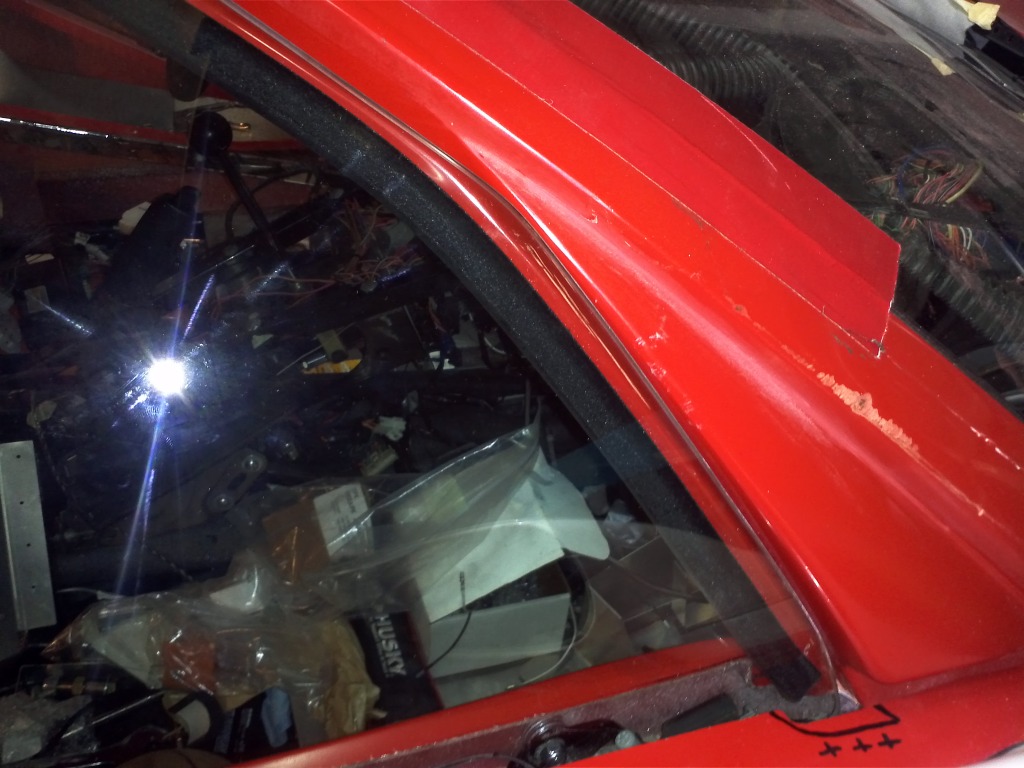
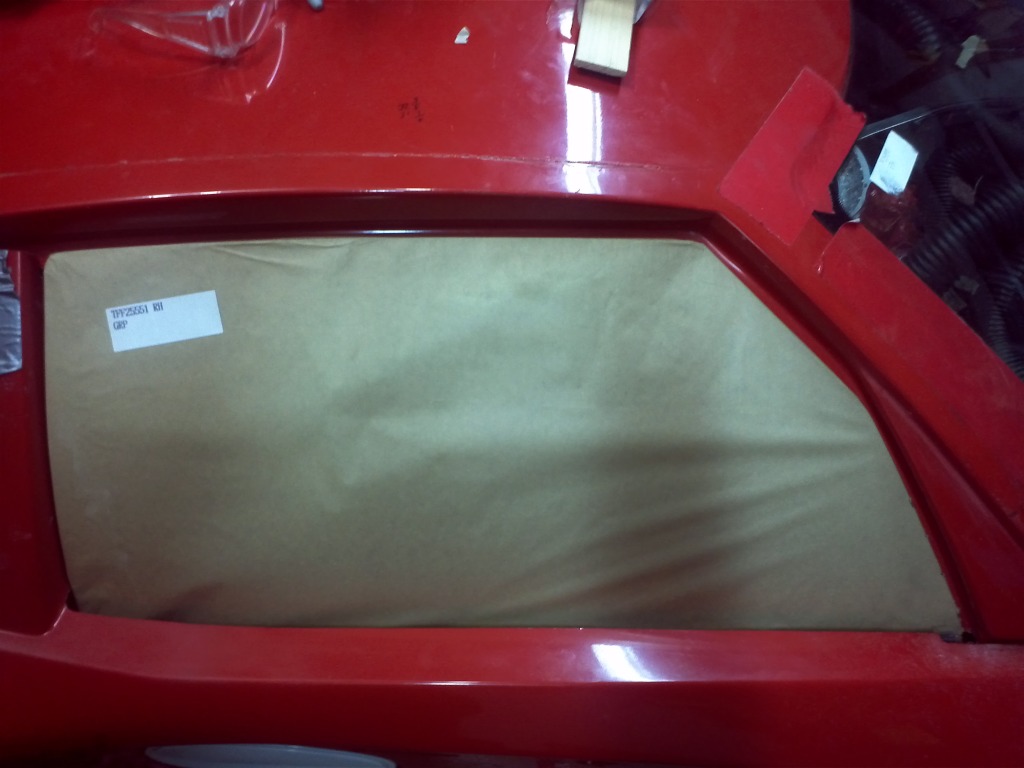
I have the window functioning with the felted weather seal installed. The window still needs tweaking as it is not contacting the seal at the top.
I have the window functioning with the felted weather seal installed. The window still needs tweaking as it is not contacting the seal at the top.
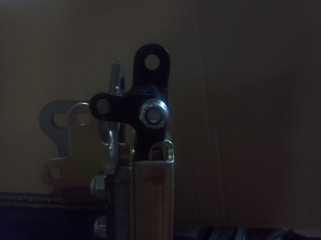
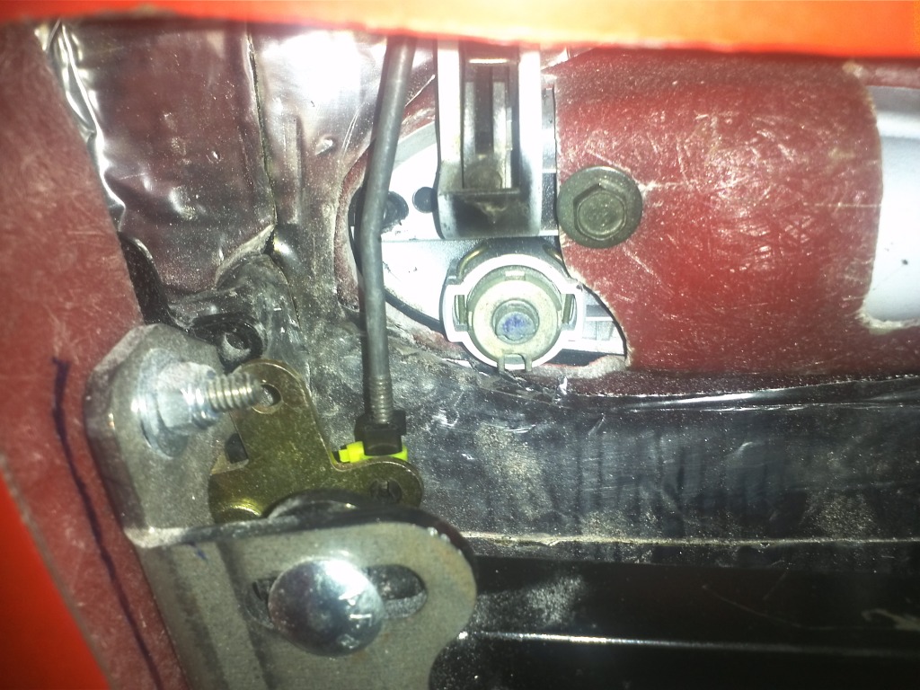
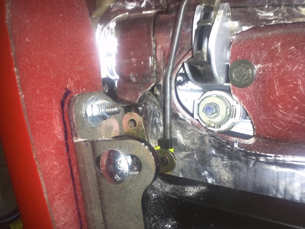
Driver's Door Handle Lock Mech
I am doing door locks. The Gen1 kits shipped with a door latch mech that included a lock mech. The manual instructs you to remove it prior to installing the door latches. The Gen2's door latches do not include this item. After doing some research I was very sure that the "Small Bear Claw" Door Latch was the same/extremely similar to the included latch. So I ordered a set of which included the lock mech. They are a perfect match. I will have the mechanical lock/unlock interior switch function along with an actuator for the power feature.
I also installed the door handle
I also installed the door handle

Passenger Side Power Window Adjustment with Felted Weather Strip Installed
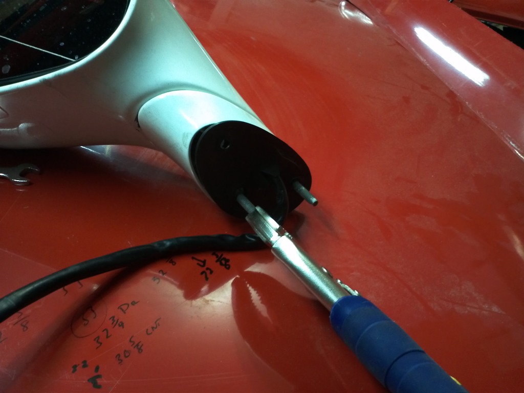
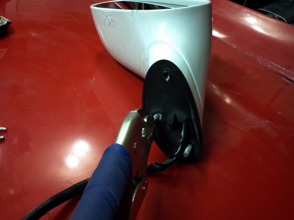
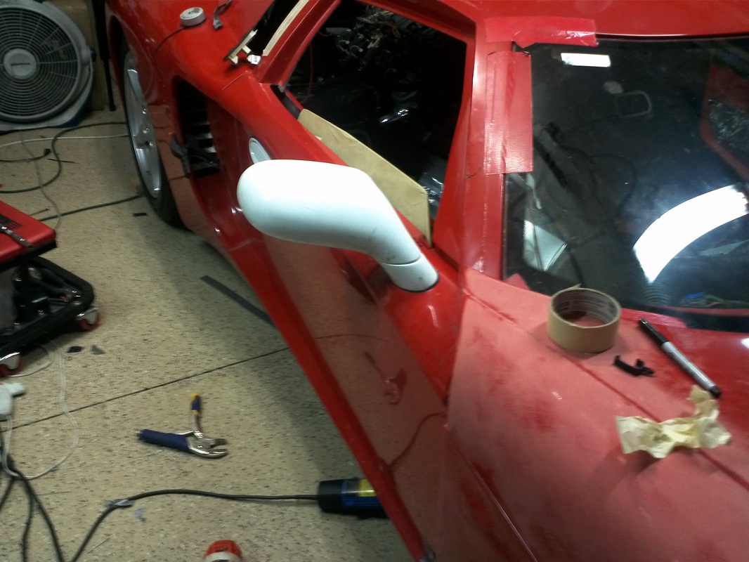
Driver's Side Power Mirror Install
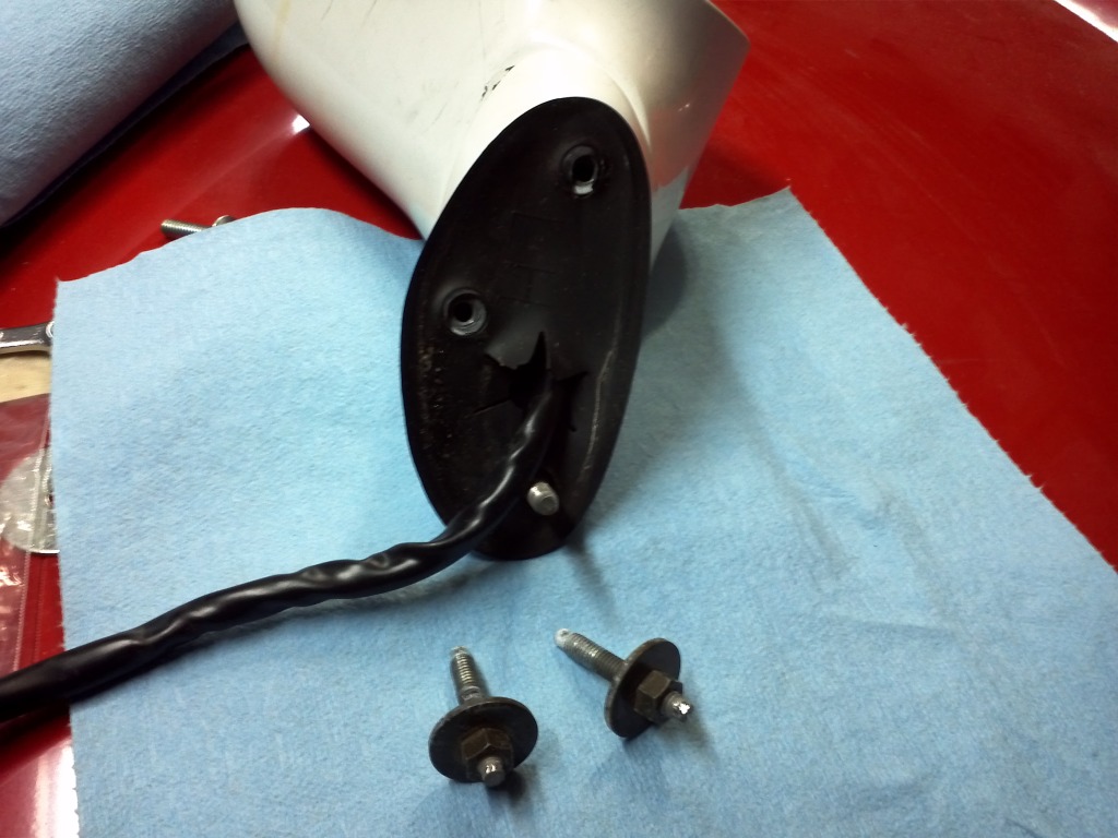
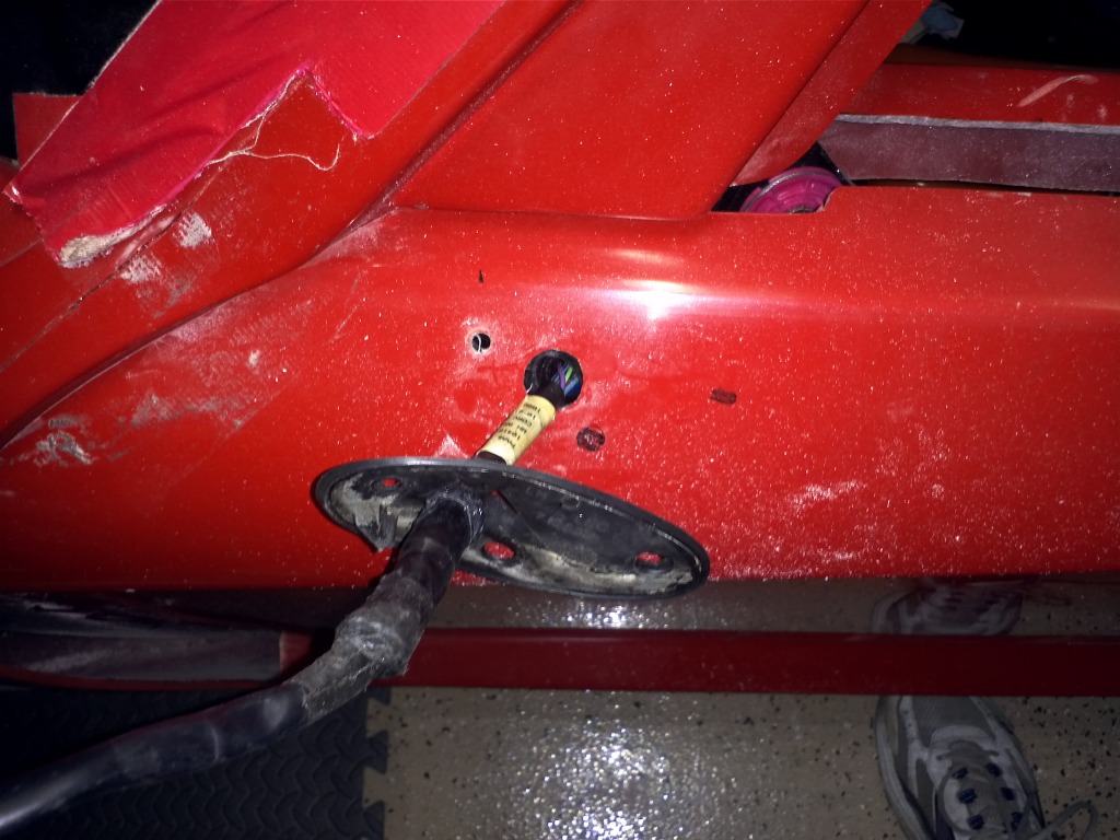
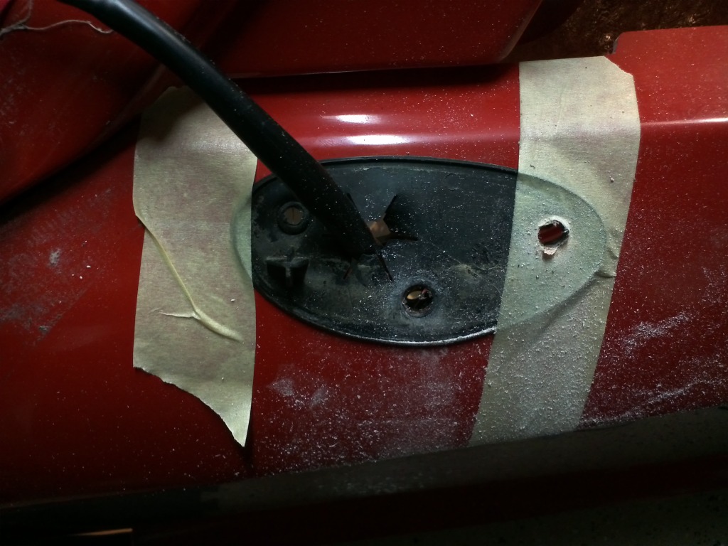
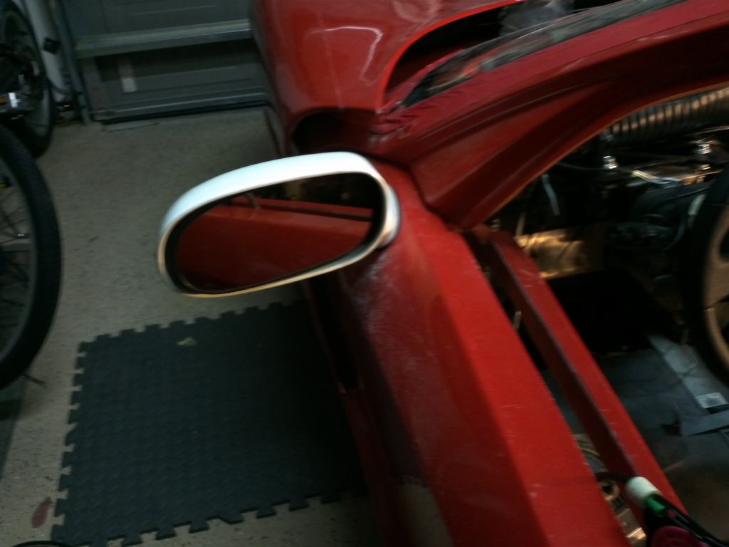
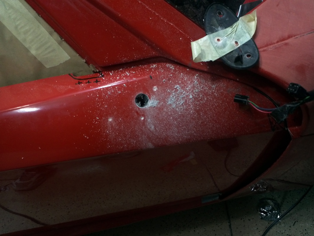
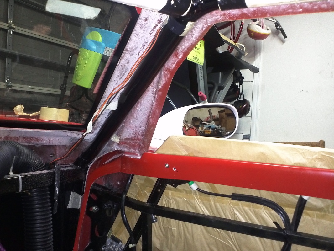
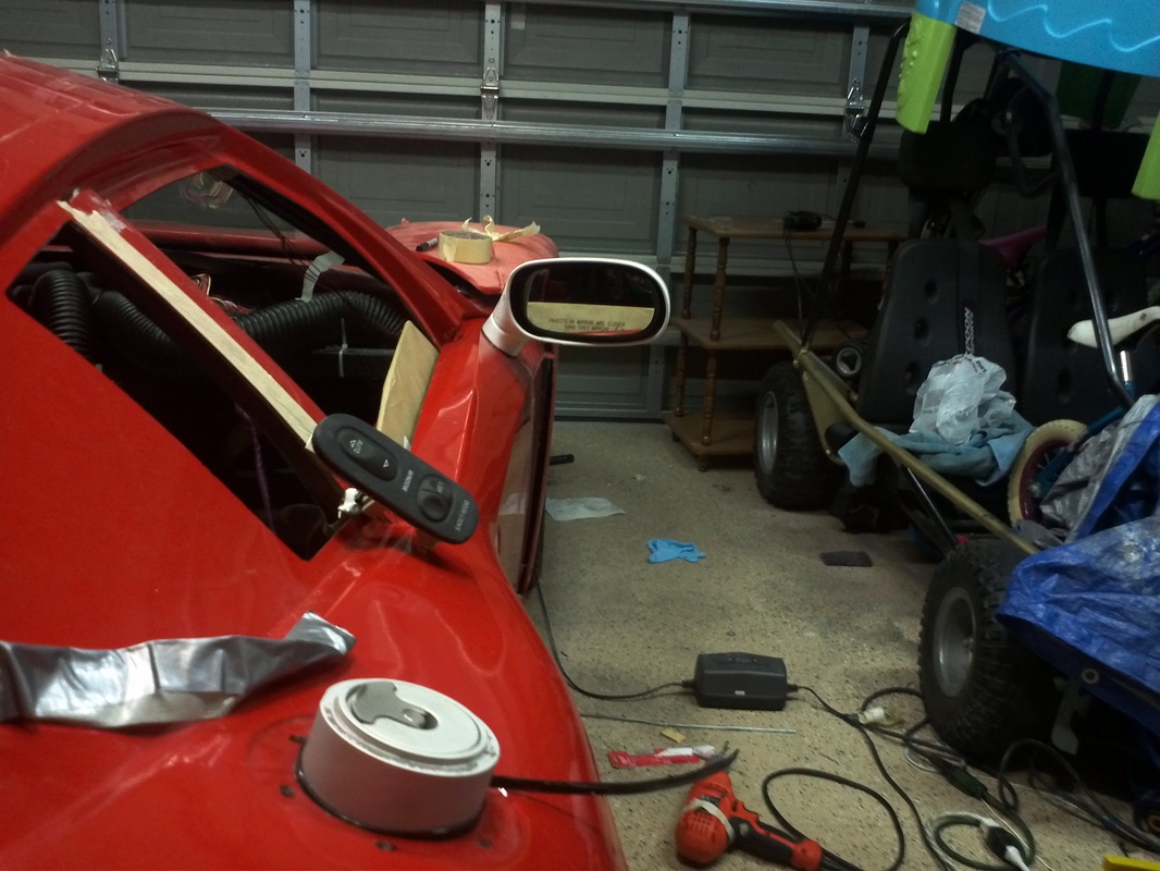
This install was quick and painless after learning from installing the passenger side power mirror. After measuring 2 1/4" as per the manual I removed the two aft studs from the mirror housing. I then placed the mirror's rubber gasket in position using the passenger side for reference. I then drilled the forward 1/4" hole and a 3/4" hole for the mirror's harness. I then placed the mirror on the door and hand tightened the nut so that I could rotate the mirror but it would not move on it's on. I took some measurements form the passenger side and set the driver's mirror to match. Then I sat in the GTM to ensure the mirror would be functional. I then carefully slid some tape between the mirror and the rubber gasket to hold it in place. I then removed the mirror, drilled the two aft holes, replaced the studs and installed the mirror.
          |
|
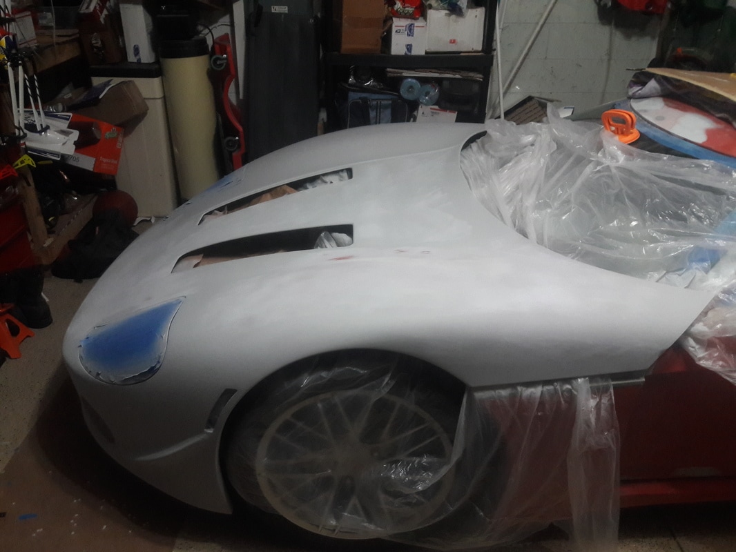
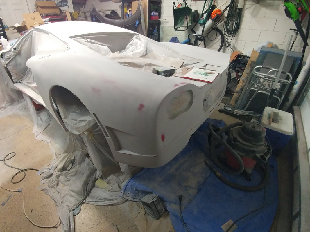
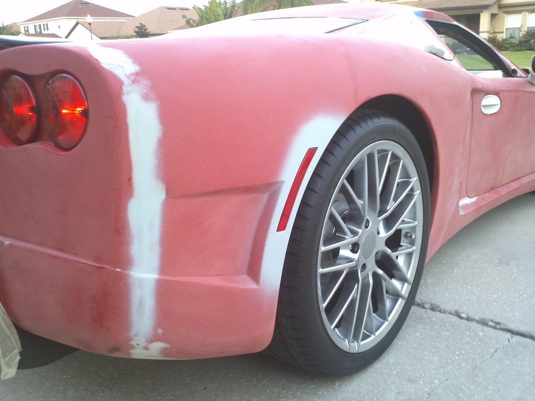
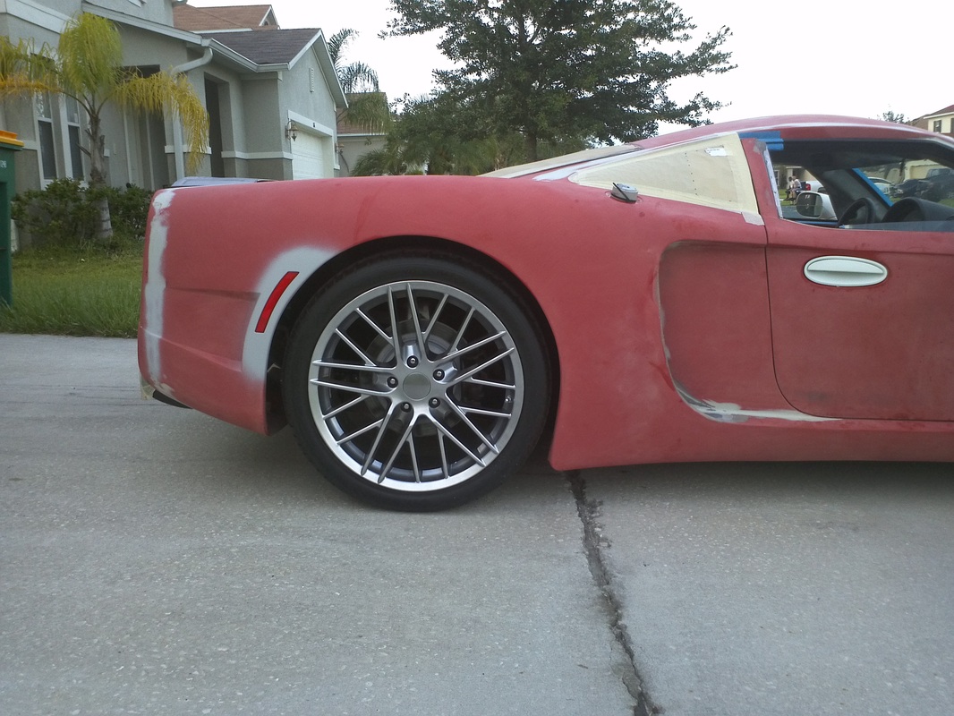
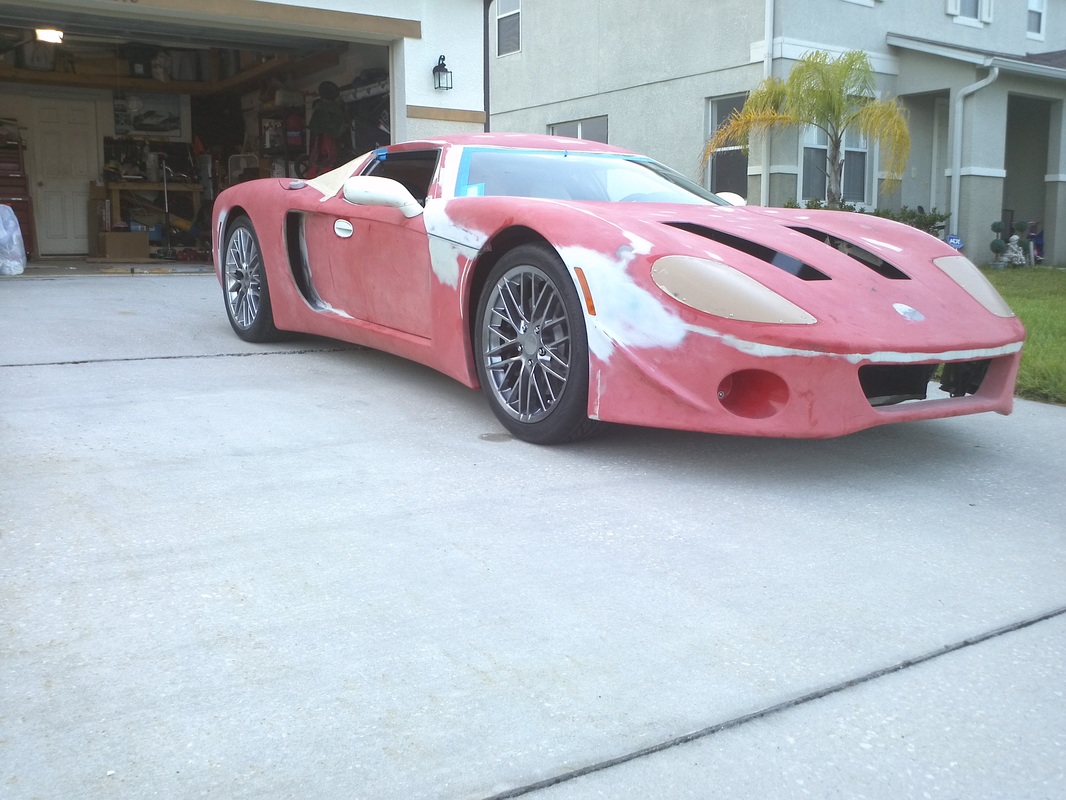
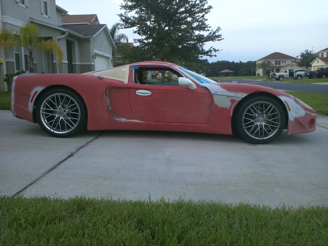
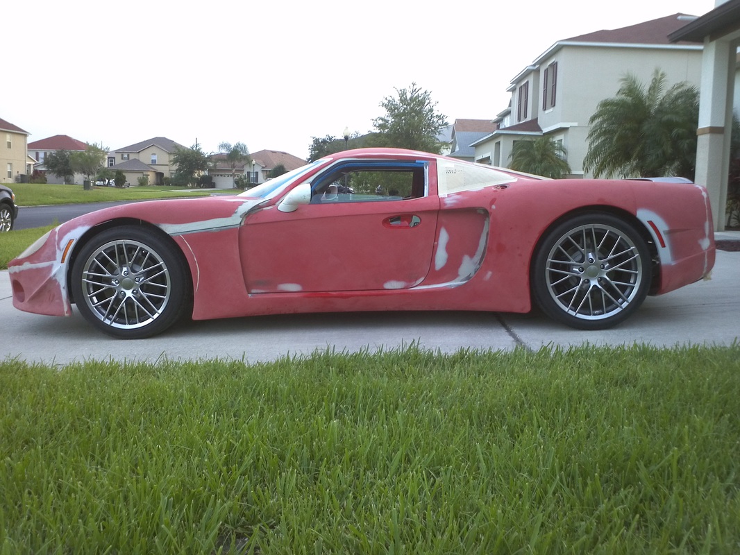
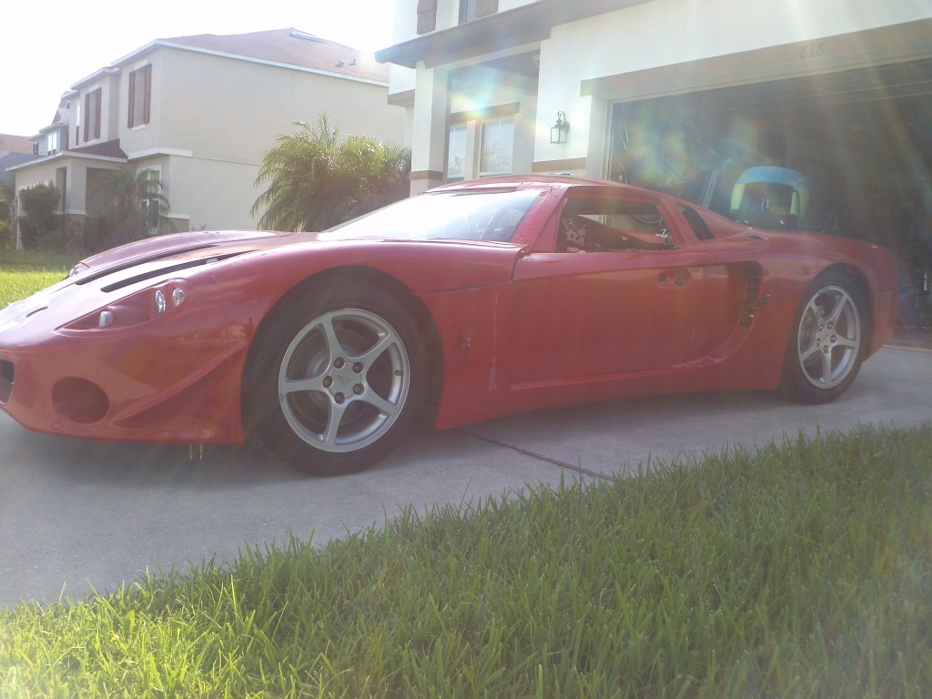
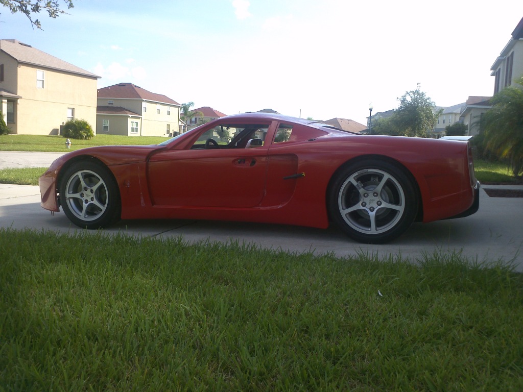
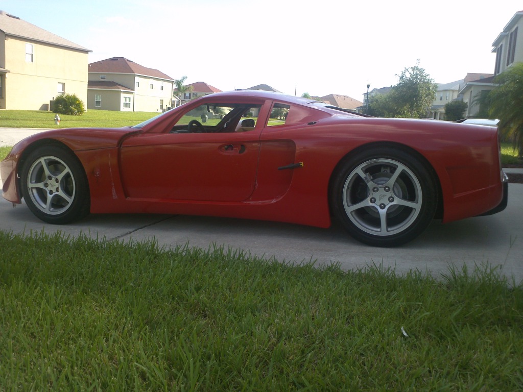
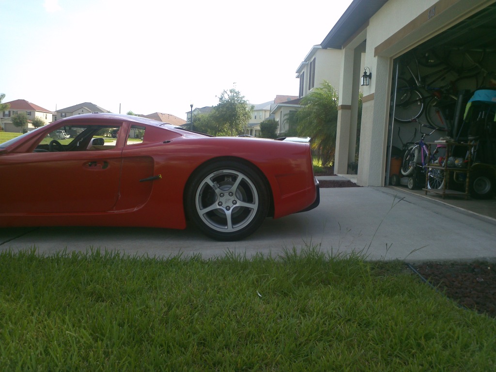
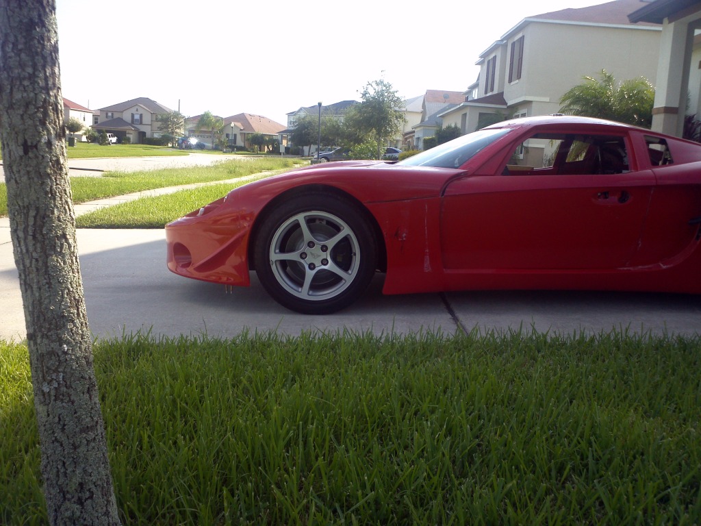
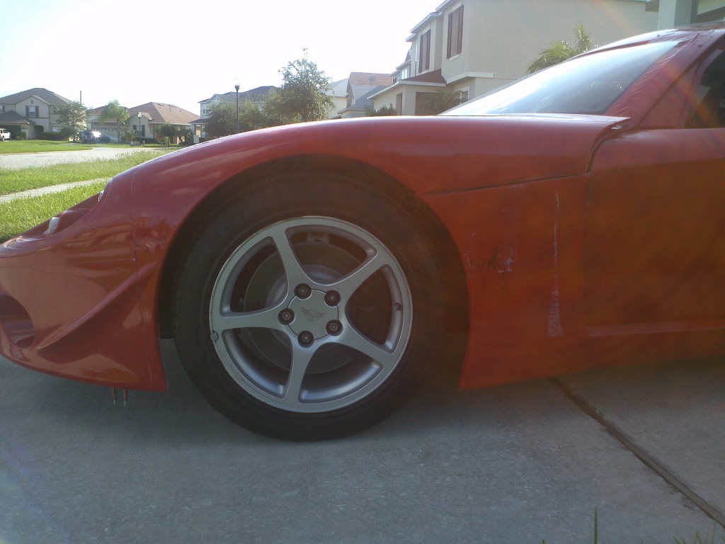
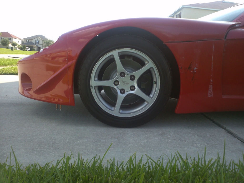
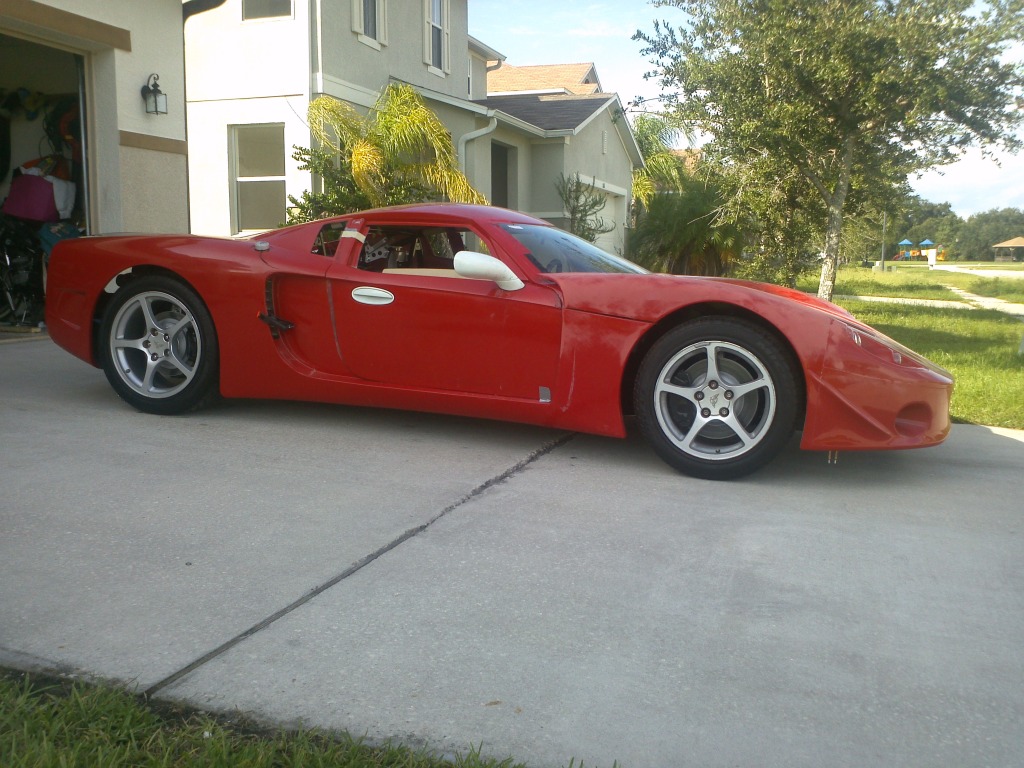
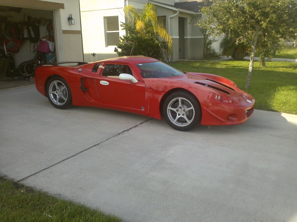
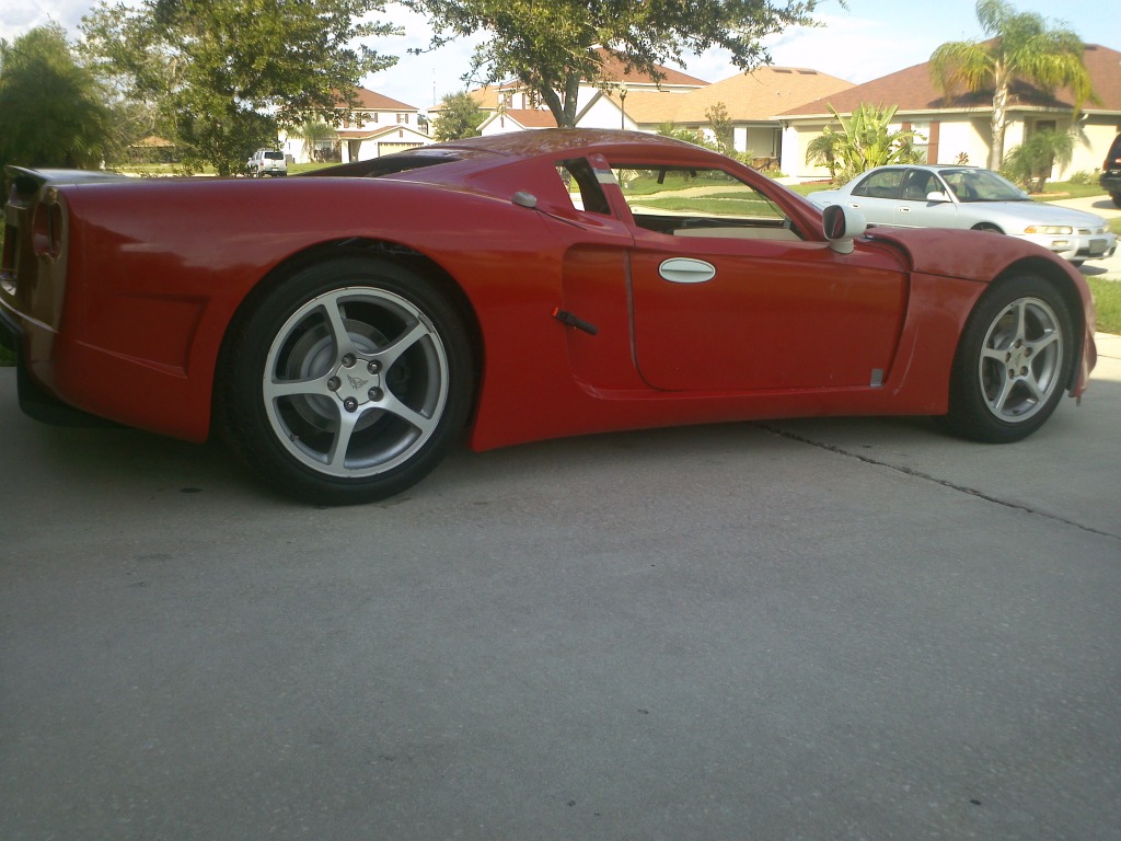
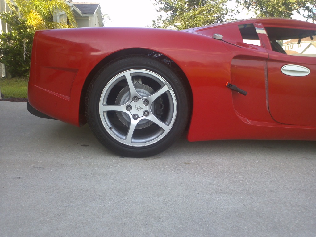
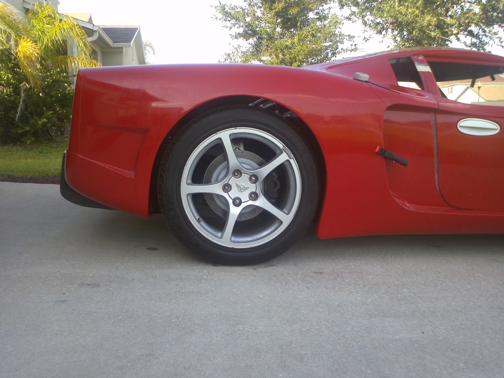
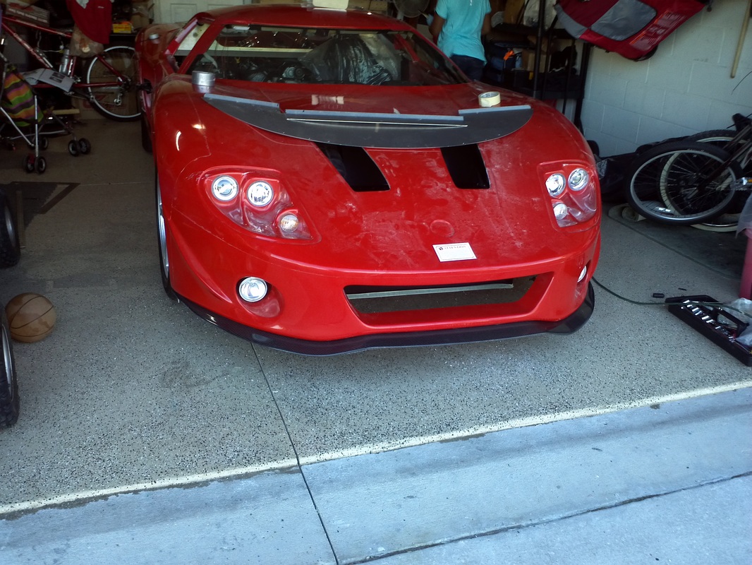
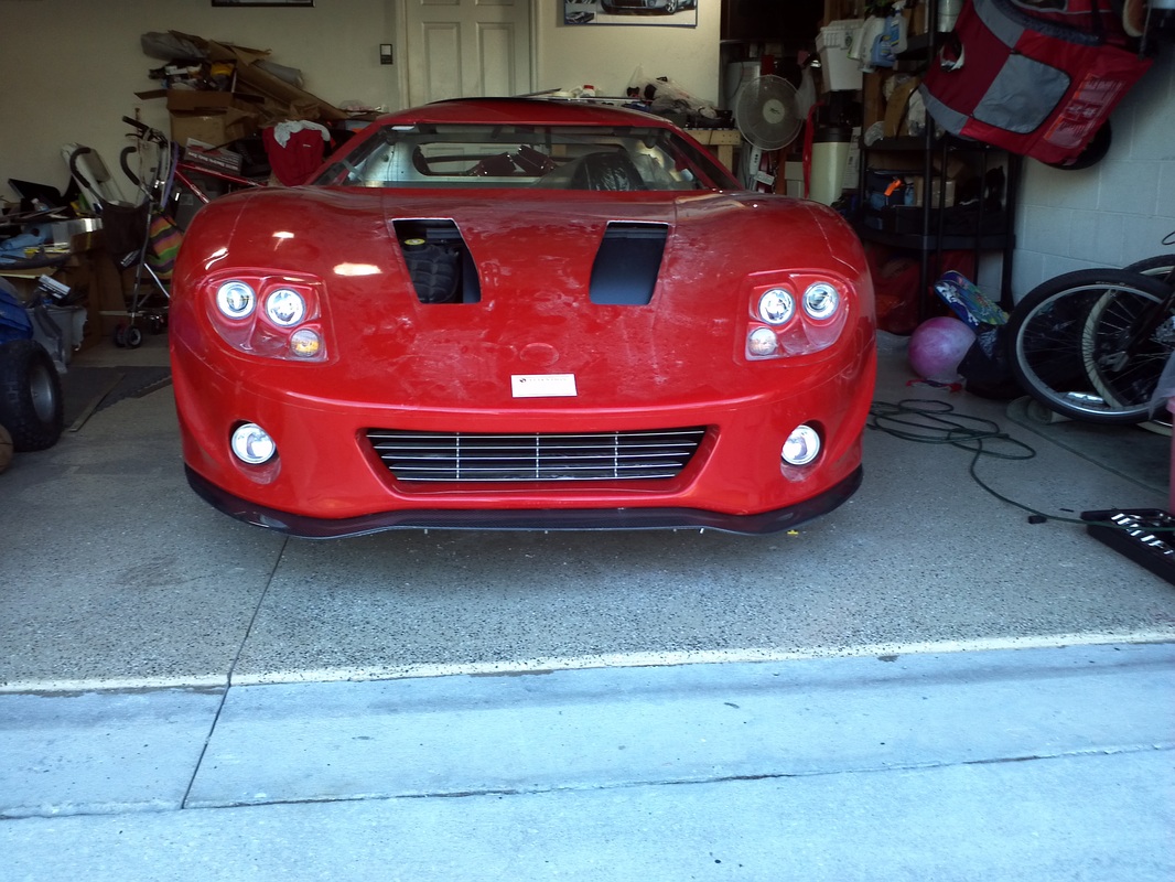
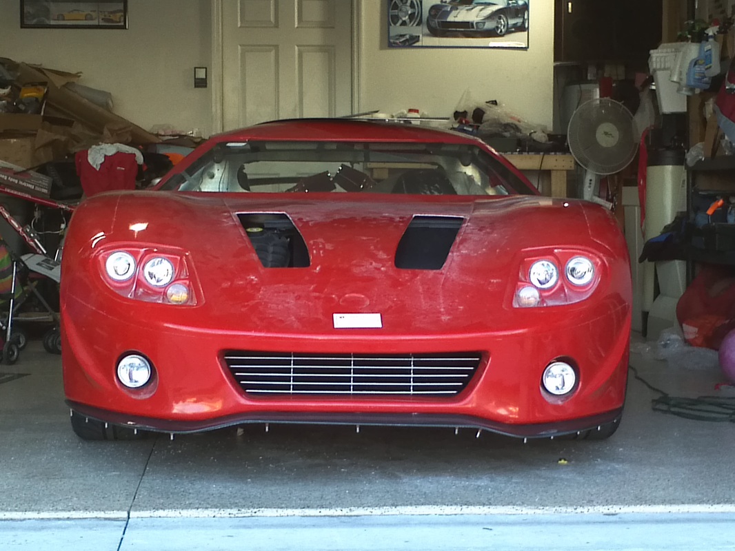
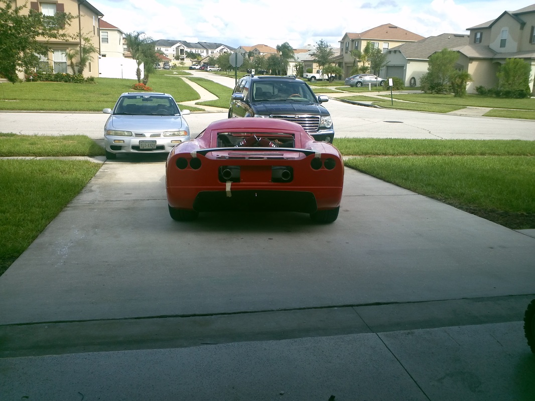
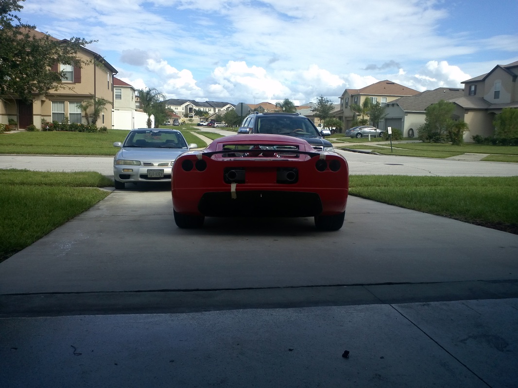
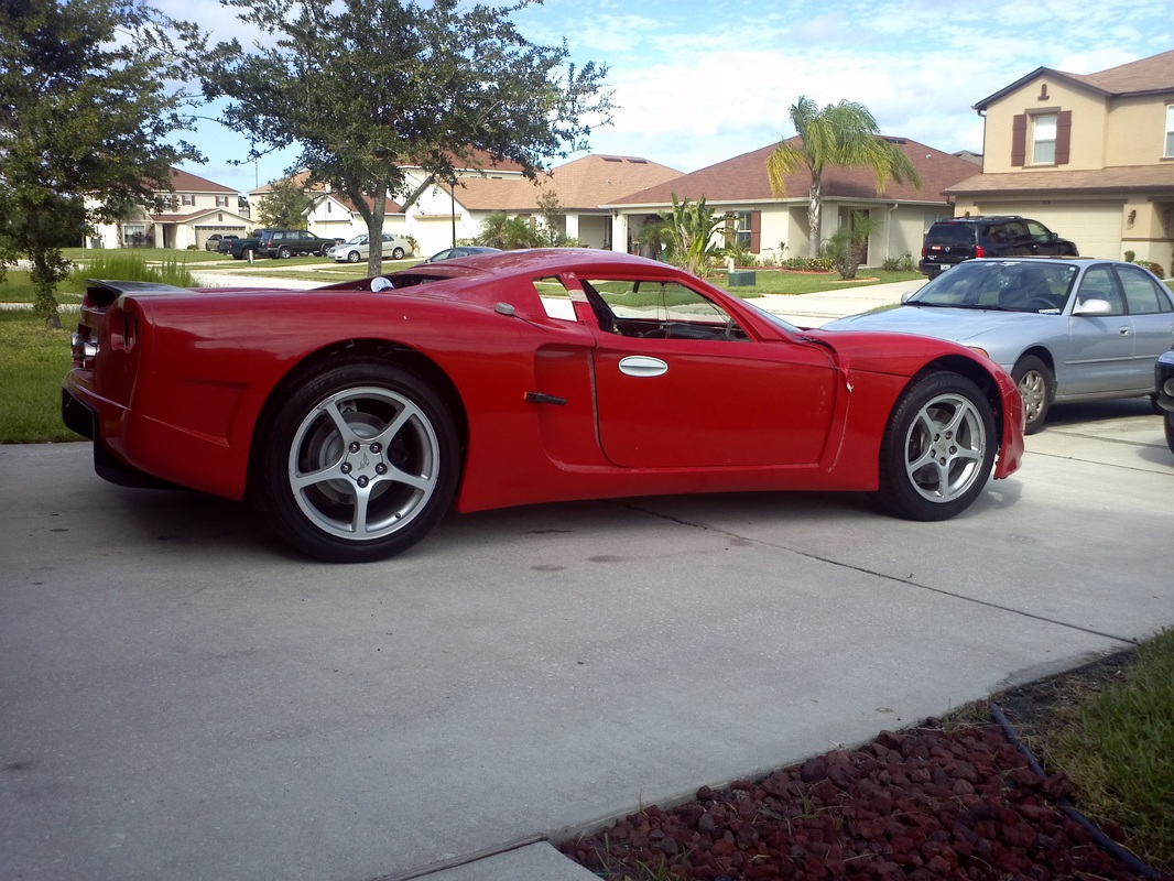
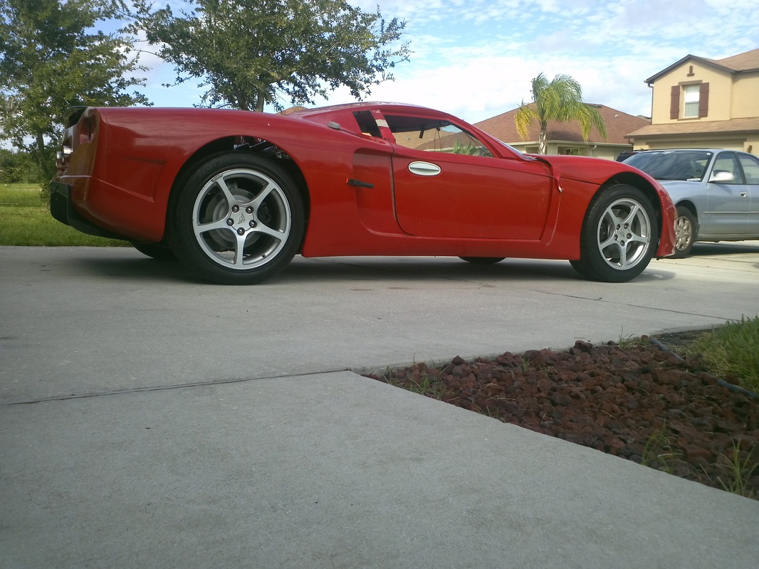
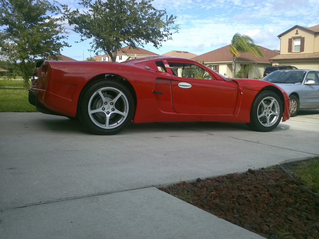
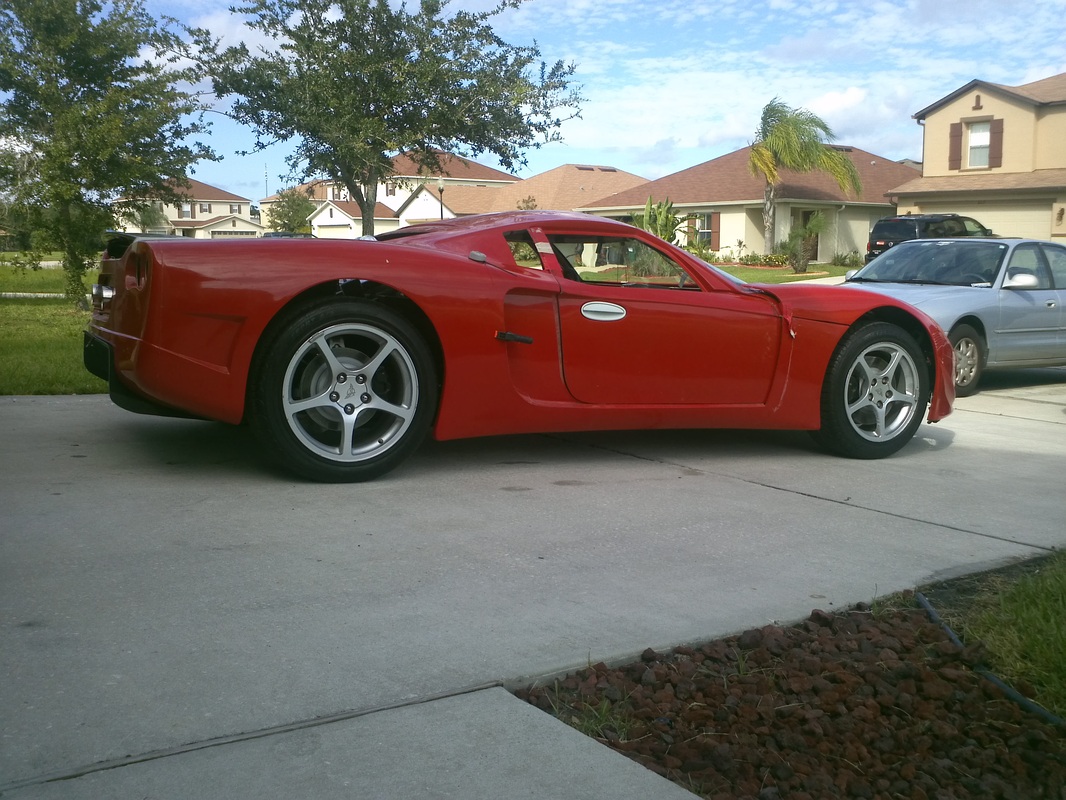
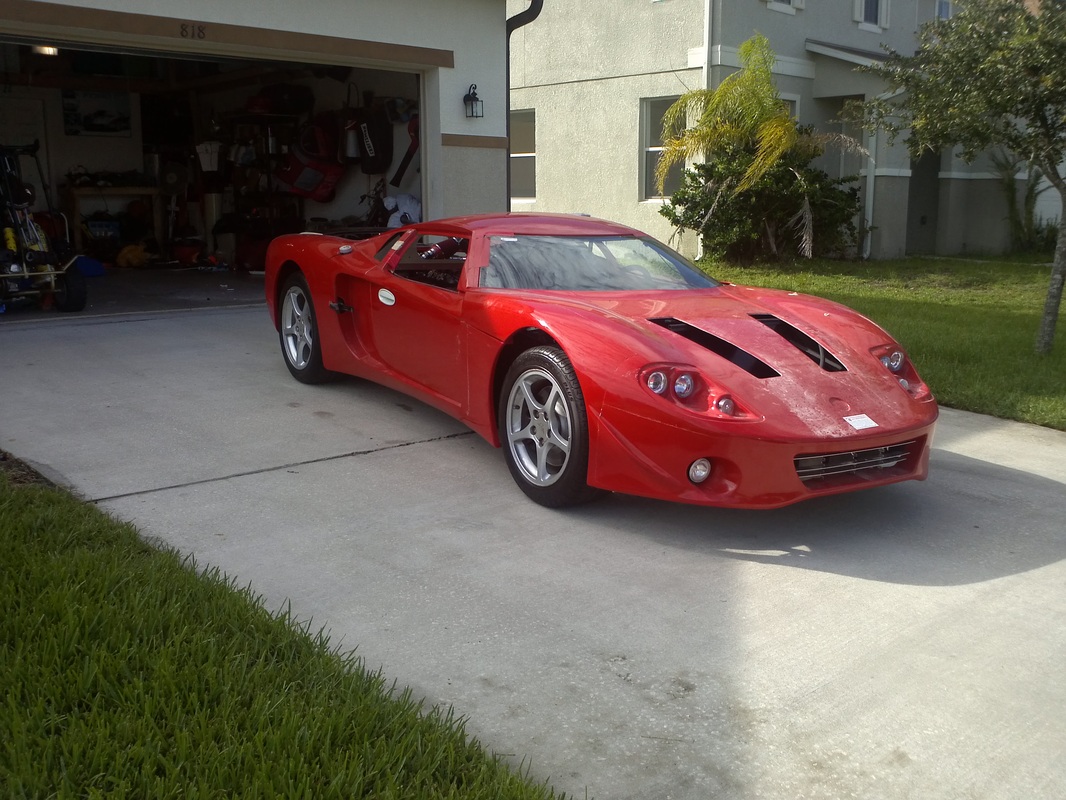
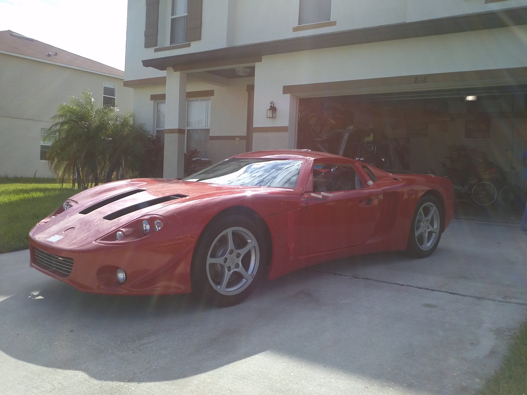
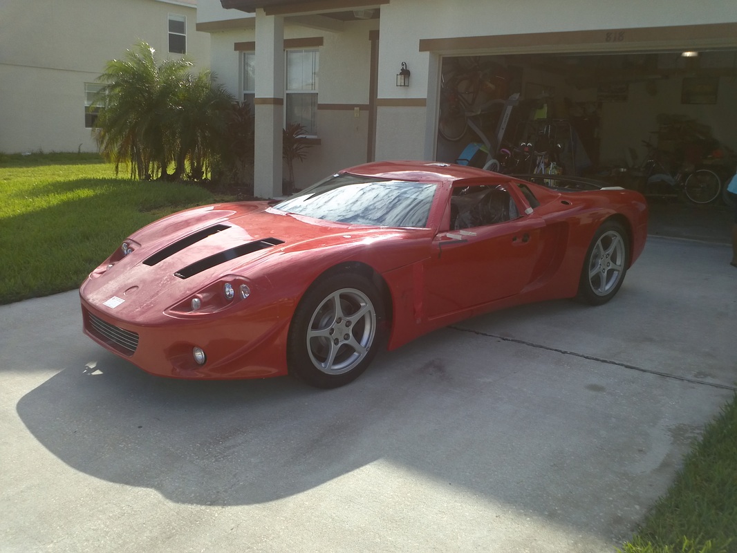
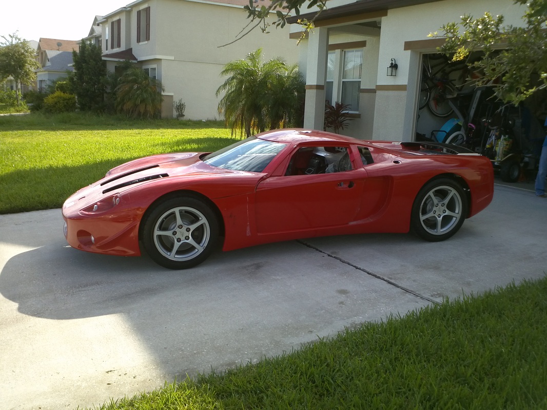
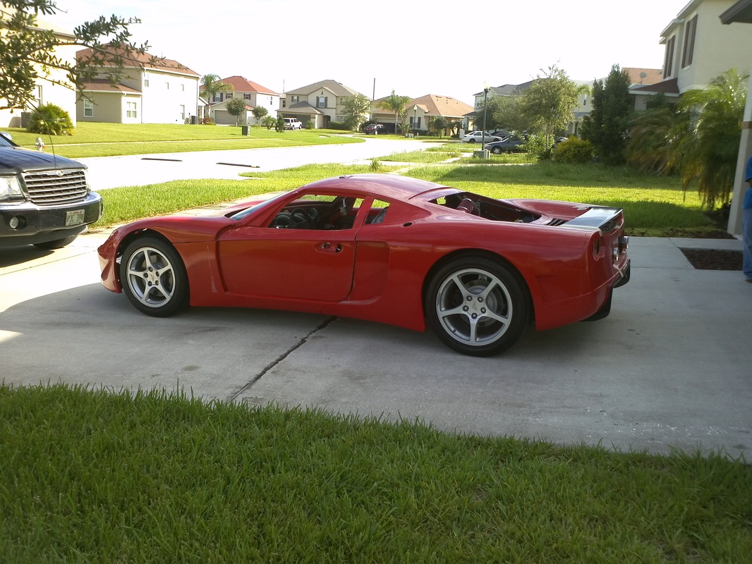
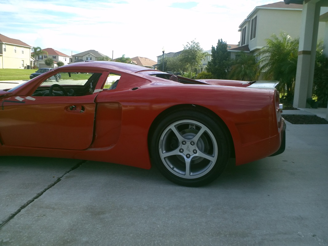
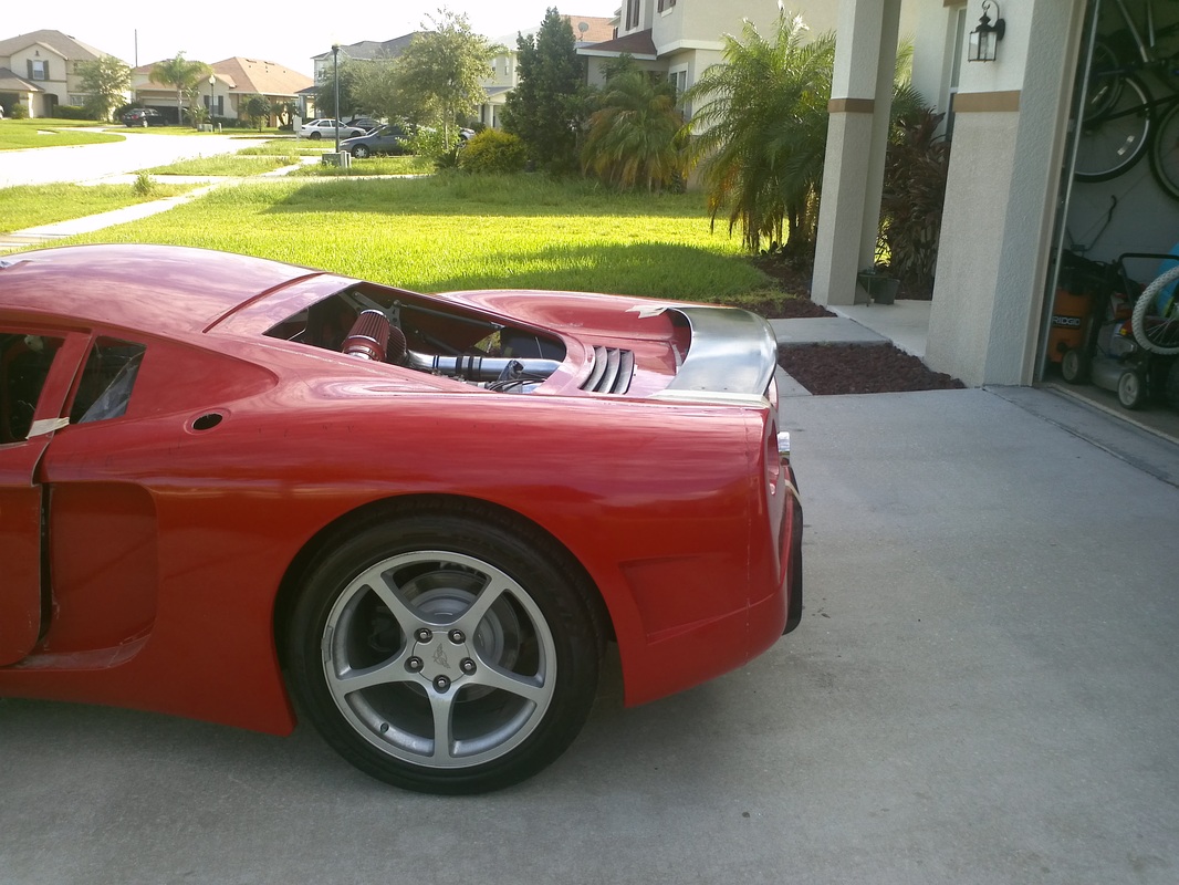
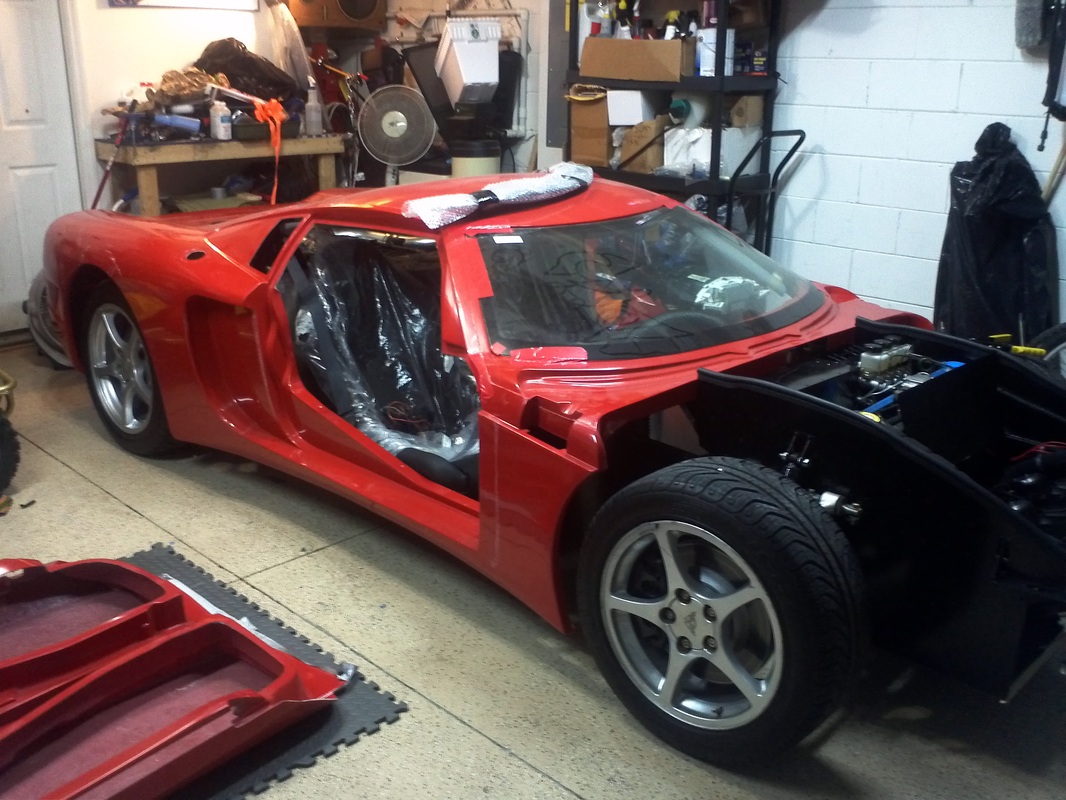
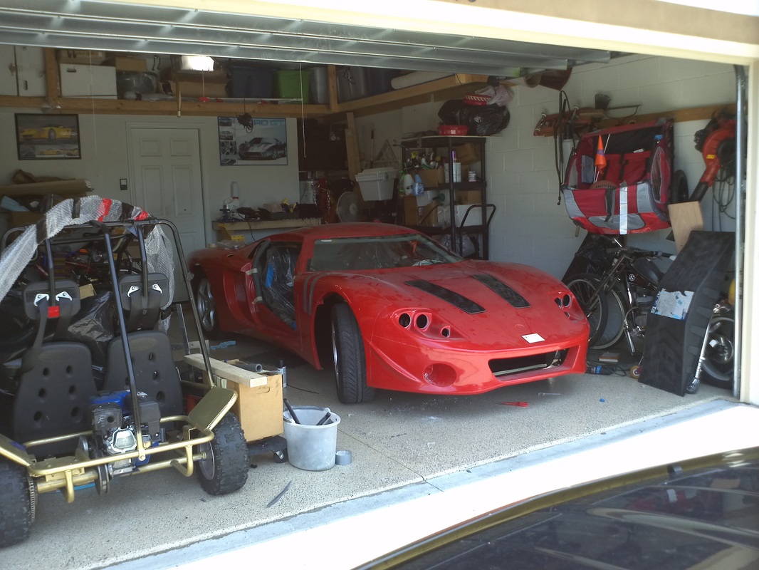
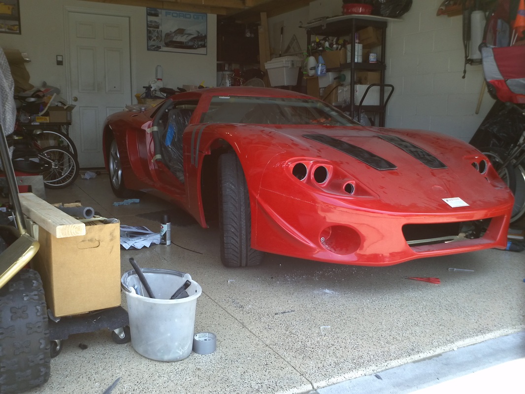
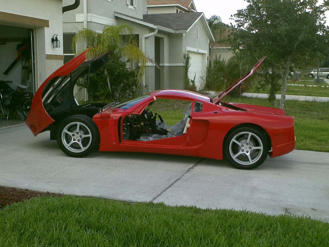
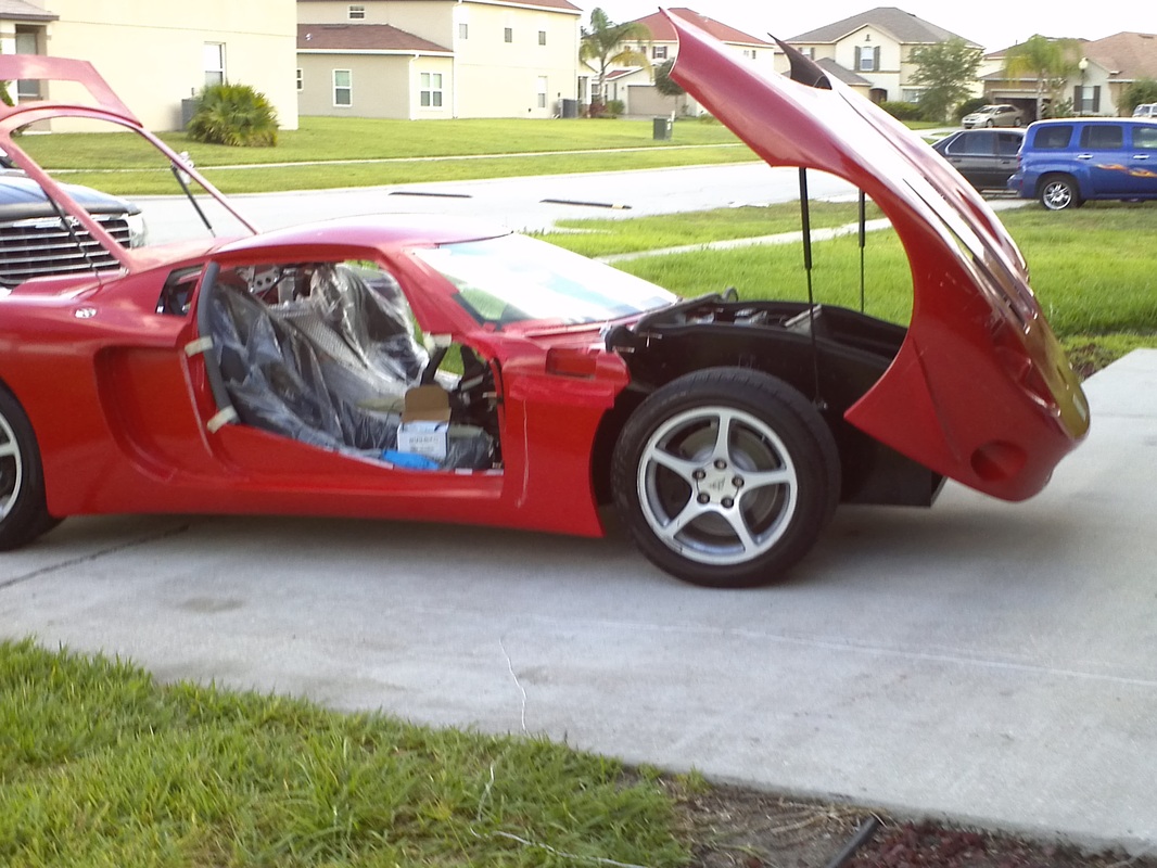
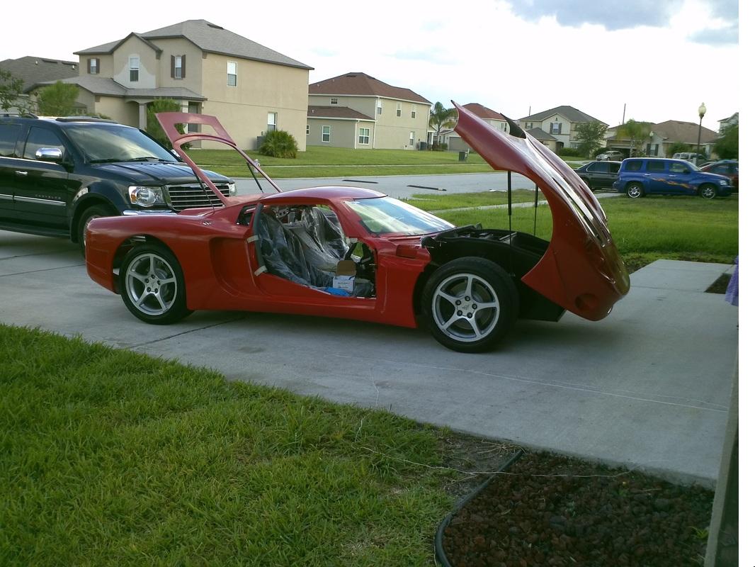
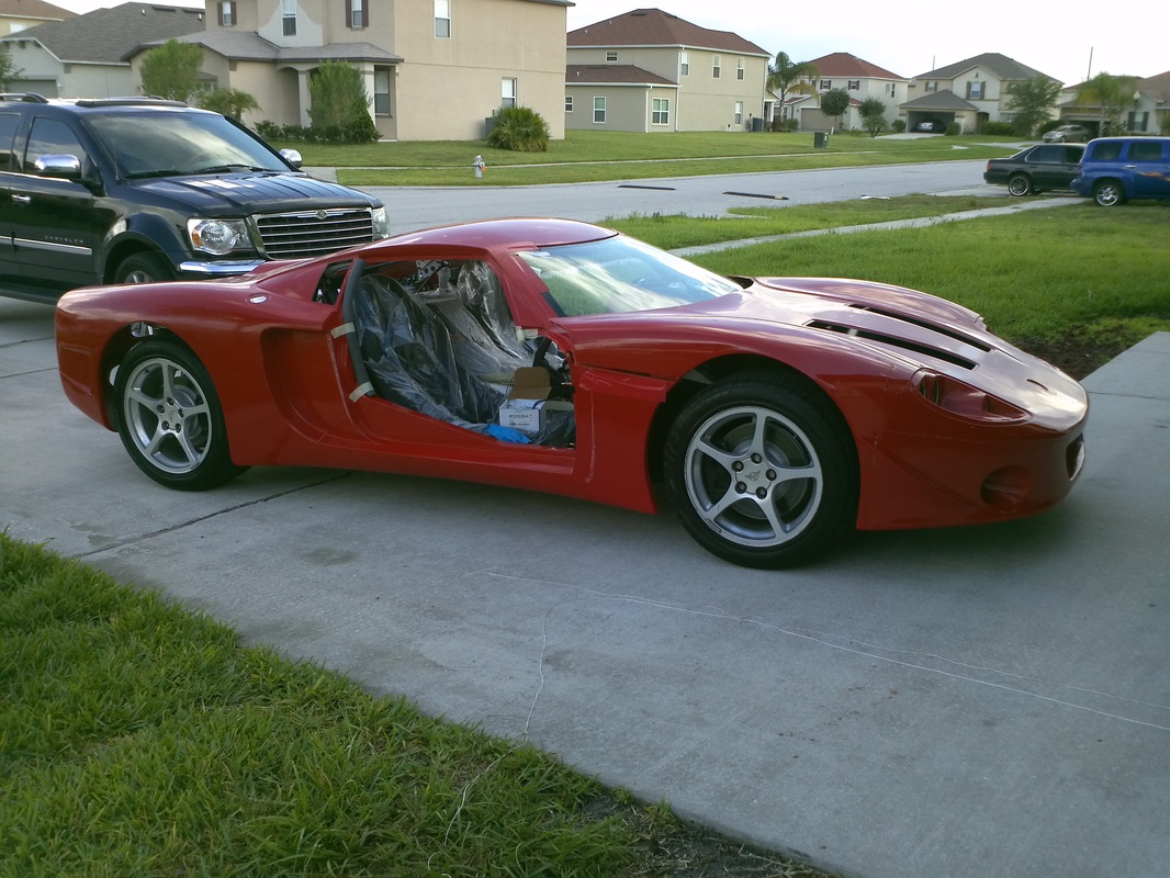
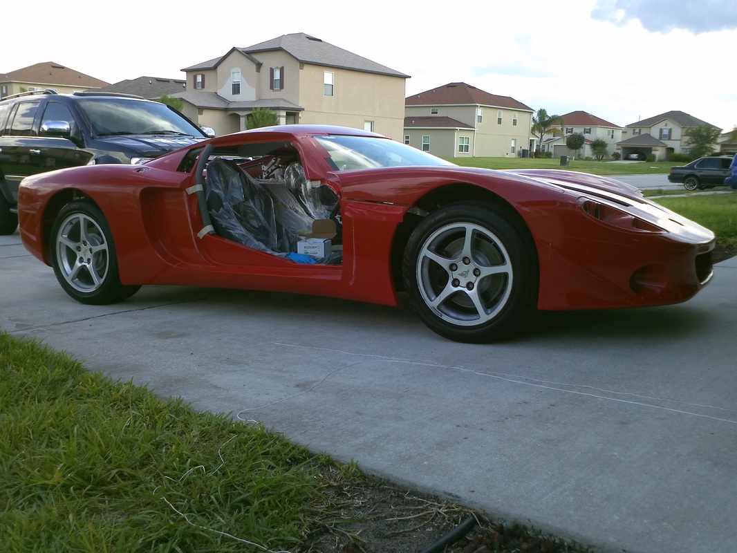
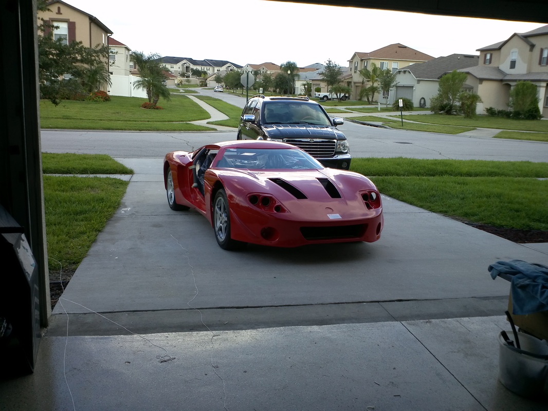
Overall Body Progress Pics. Latest Set.
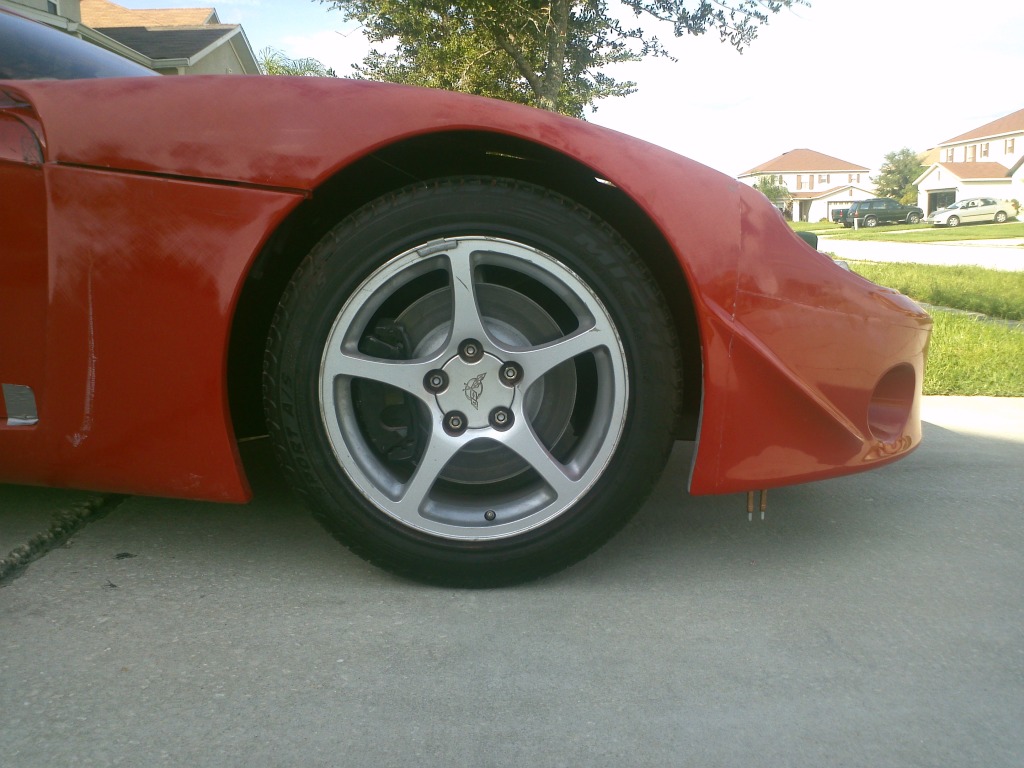
I adjusted the ride height to 4 3/4". The wheel wells all look good with the exception of the passenger side front. This wheel arc is further away from the tire in the 10:30 clock position. I need to make some adjustments to the hood which will close the gap. I am considering adding to this area, but am cautious, because of the flex that happens with the hood when closing. I'll reevaluate it once the hood is adjusted.


Passenger Side Power Window
With some helpful information from Rumrunner and Kempo I was able to get the passenger side window installed. There was no need to cut and weld the door frame for clearance. I am using the corvette door module and switch.
|
|
|
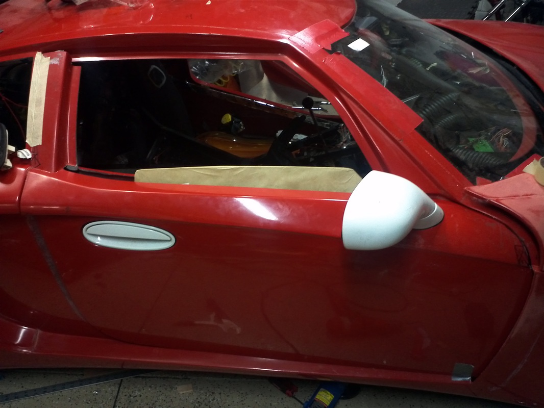
Passenger Side Power Mirror
With the door and window installed I moved to the power mirror. I removed the mirror's mounting studs to aid in installation. With the studs removed it was easier to place the mirror to see how it looked on the door. From there I installed it per the manual and then sat in the driver's seat to test it's functionality. I am using the corvette door switch in my GTM which has the mirror controls. When I sat in the seat I could see that Installing the mirror per the manual does give it very level appearance, but is not very functional. There was not enough adjustment in the mirror. I could not see any higher than the top of the rear wheel. So I removed the mirror, the center and rear studs and then placed the mirror back on the door with only the forward most stud. I then tightened it just enough to hold it flat against the door, but to a level that allowed me to rotate the mirror about the stud. Then I sat in the driver's seat and made adjustments that allowed the mirror to function properly with some excess viewing area.
      |
|
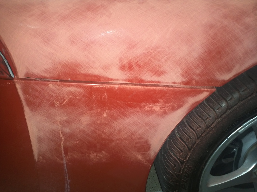

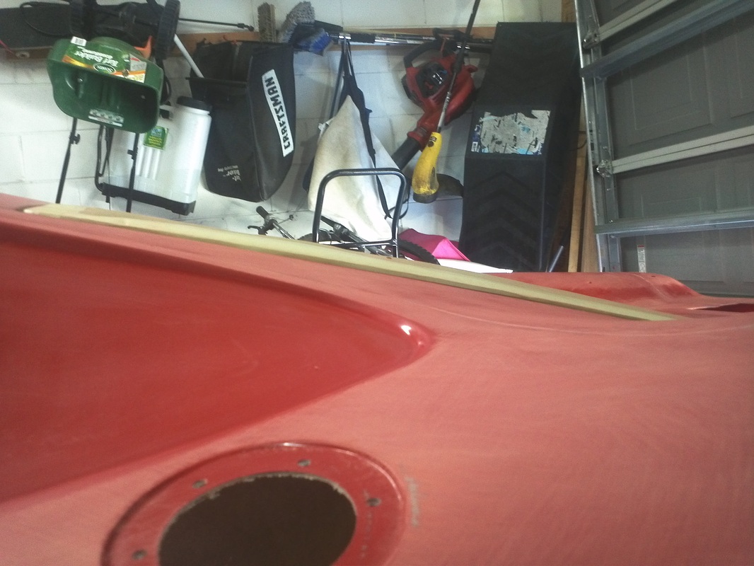
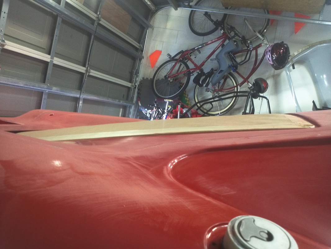
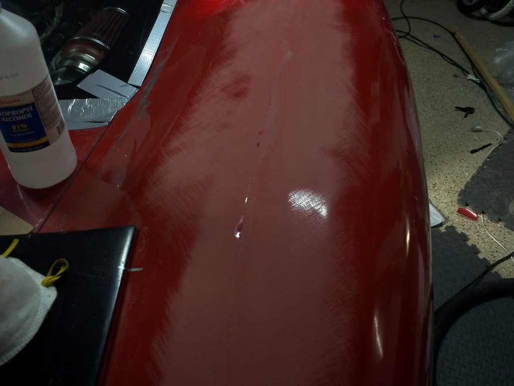
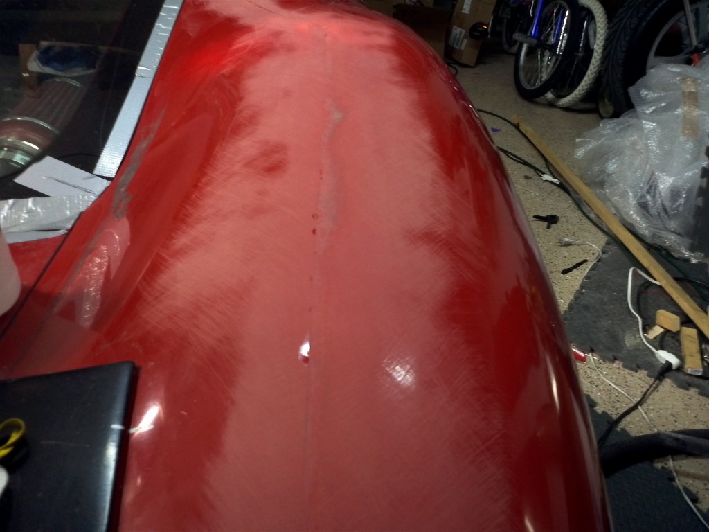
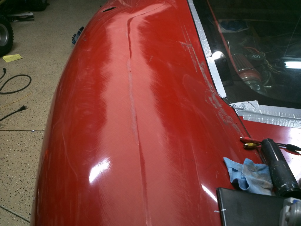
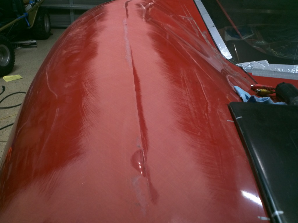
Started Blocking on the Passenger Side Hood mold line area
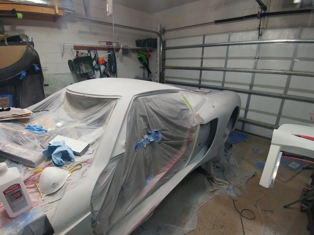
I purchased The Paintucation DVD and have been doing research online as well as applying some tips from my painter. My goal is to do all of the body work myself all the way through wet sanding my final coat of Slick Sand polyester spray filler. I have mounted the hatch, hood and initial fitment of the doors. I have run into an issue with my roof resting on the chassis (it should not be) that is affecting the door openings. So I have only trimmed and mounted the doors and will hold there until the issue is resolved. With these mounted I have not done any gapping, but I am very confident that I will be able to complete all of this with very professional results.
Because the molds are very good and the seams are done extremely well the process for the mold lines will be this. I will initially block the area around the mold lines. This knocks down some of the really high points of the mold lines, exposes some of the voids and takes care of some of the initial blocking. The voids will be filled with Evercoats Rage lightweight filler and blocked.
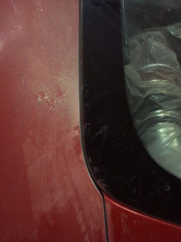
I grabbed my long flexible blocking bar and a strip of adhesive backed sand paper to test out my blocking skills on the area around the mold lines atop the hood passenger side. Using the 45 degree or "X" I proceeded. I was working on a small area, but found the technique to be easy to follow and very natural after a few minutes. The hood in this area is also very good. The only low area here is the inside of the mold lines along most of it there. This was just a test but I was happy with my work and what I saw there on the body. What I didn't like was all of the red dust. Body work is extremely dusty/dirty work. I will mask of the interior and cover the entire hood and engine area prior to proceeding with this. If I can get the issue resolved soon I can do the initial blocking of the doors and the surrounding so that I can put the body on a buck.
Because the molds are very good and the seams are done extremely well the process for the mold lines will be this. I will initially block the area around the mold lines. This knocks down some of the really high points of the mold lines, exposes some of the voids and takes care of some of the initial blocking. The voids will be filled with Evercoats Rage lightweight filler and blocked.
I grabbed my long flexible blocking bar and a strip of adhesive backed sand paper to test out my blocking skills on the area around the mold lines atop the hood passenger side. Using the 45 degree or "X" I proceeded. I was working on a small area, but found the technique to be easy to follow and very natural after a few minutes. The hood in this area is also very good. The only low area here is the inside of the mold lines along most of it there. This was just a test but I was happy with my work and what I saw there on the body. What I didn't like was all of the red dust. Body work is extremely dusty/dirty work. I will mask of the interior and cover the entire hood and engine area prior to proceeding with this. If I can get the issue resolved soon I can do the initial blocking of the doors and the surrounding so that I can put the body on a buck.
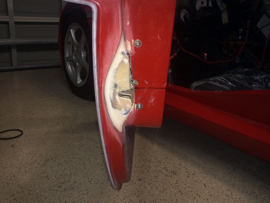
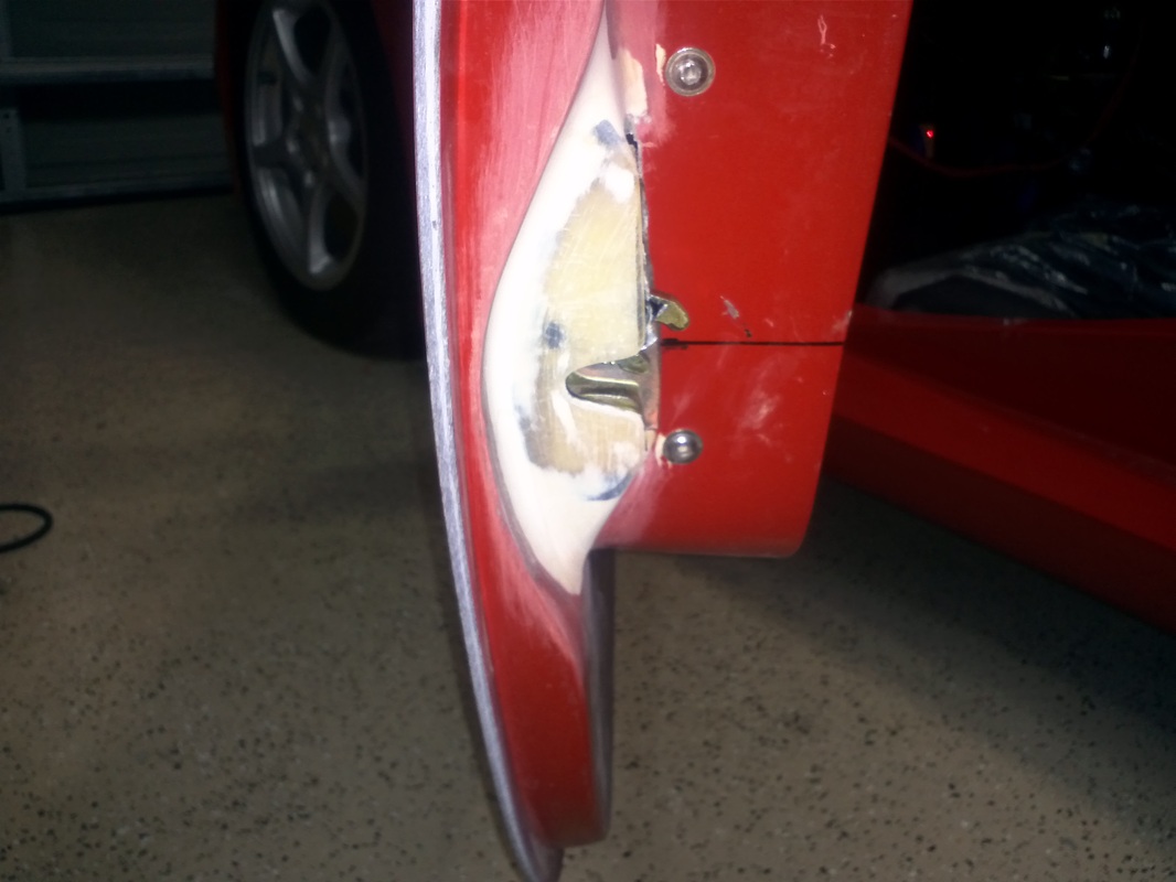
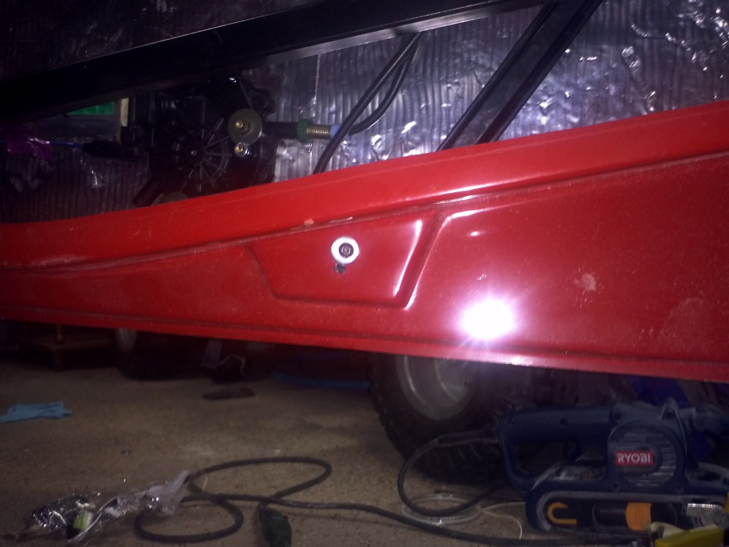
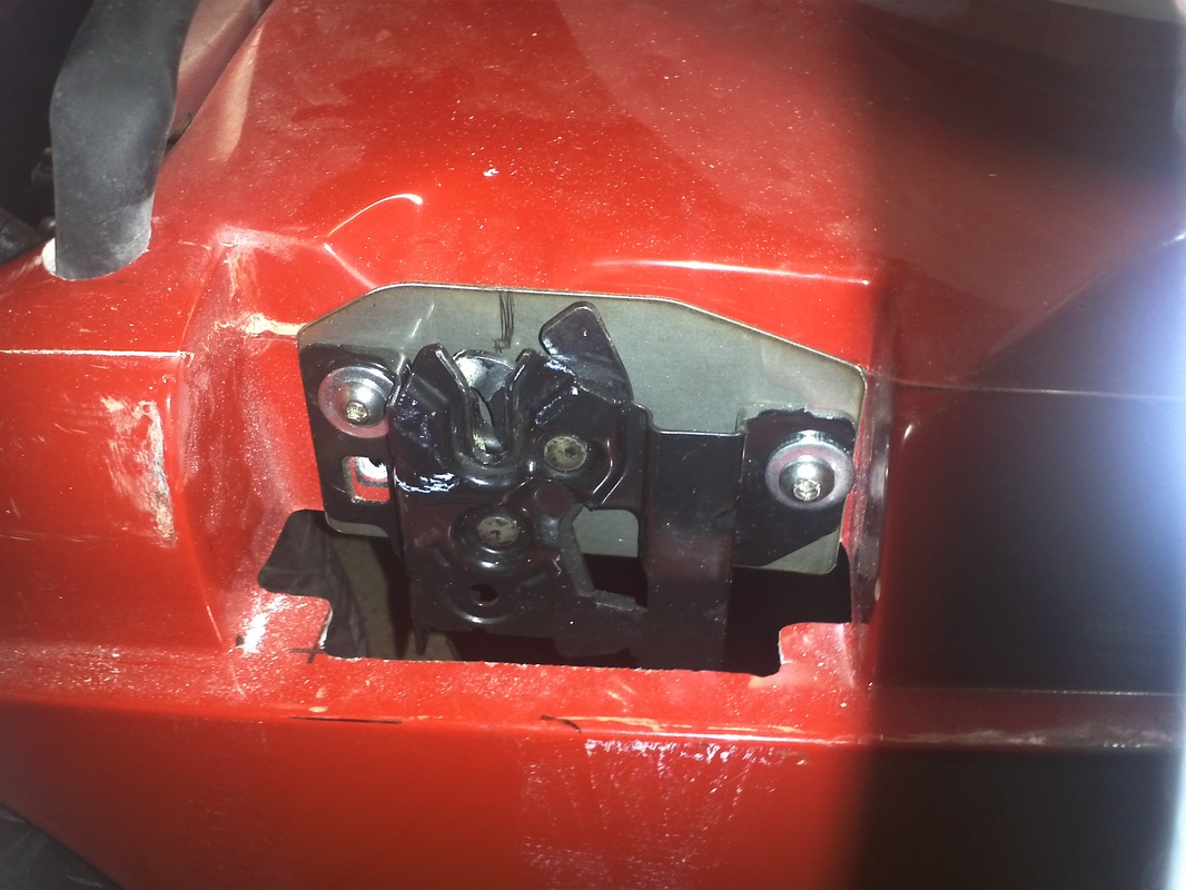
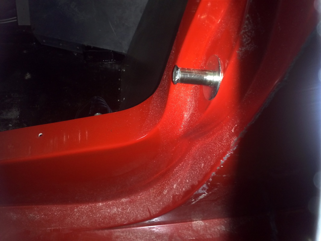
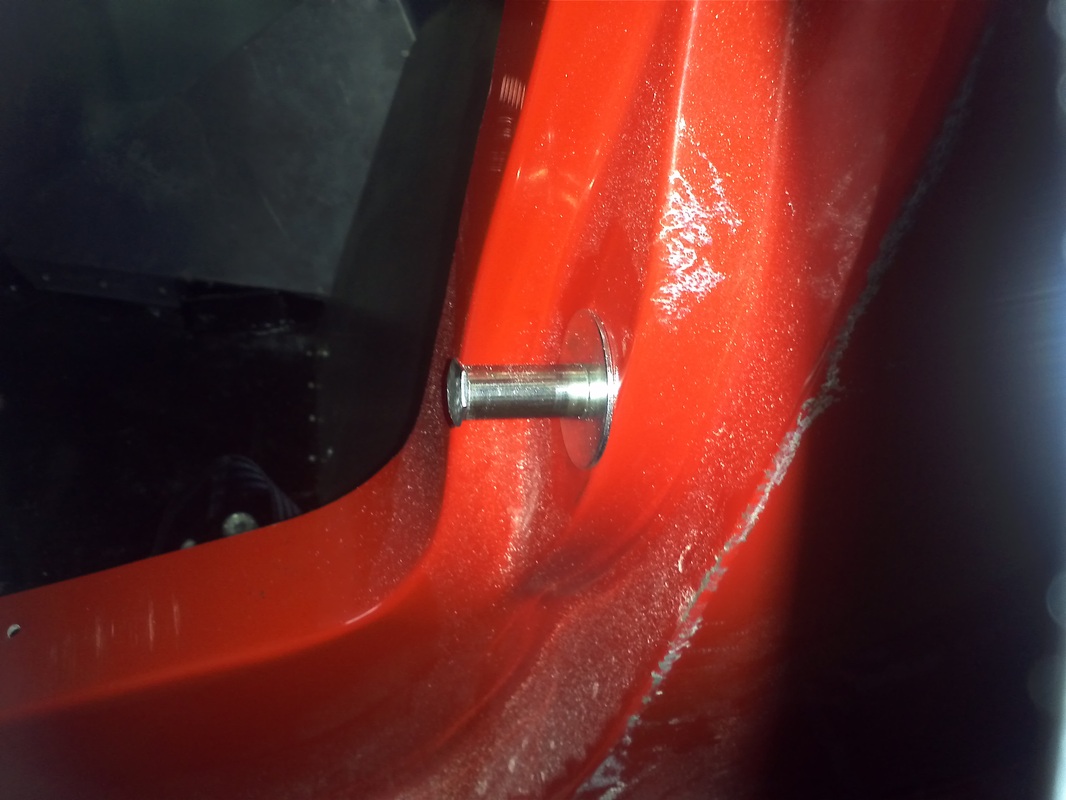
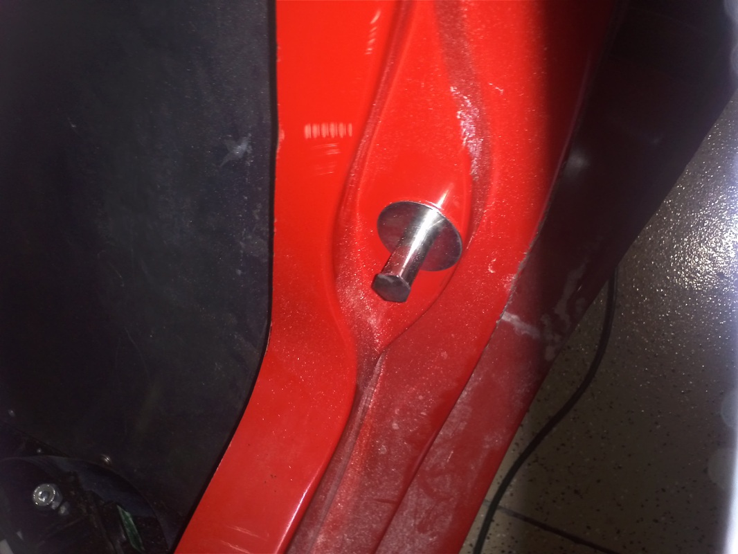
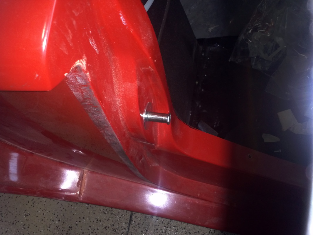
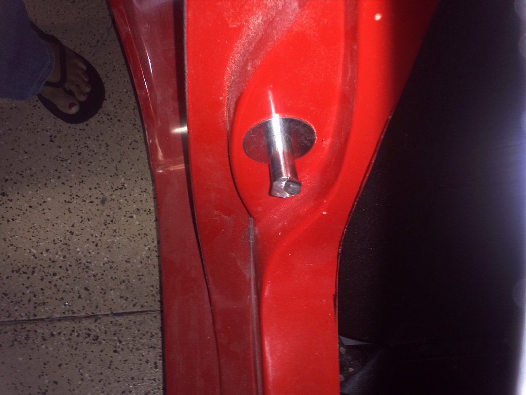
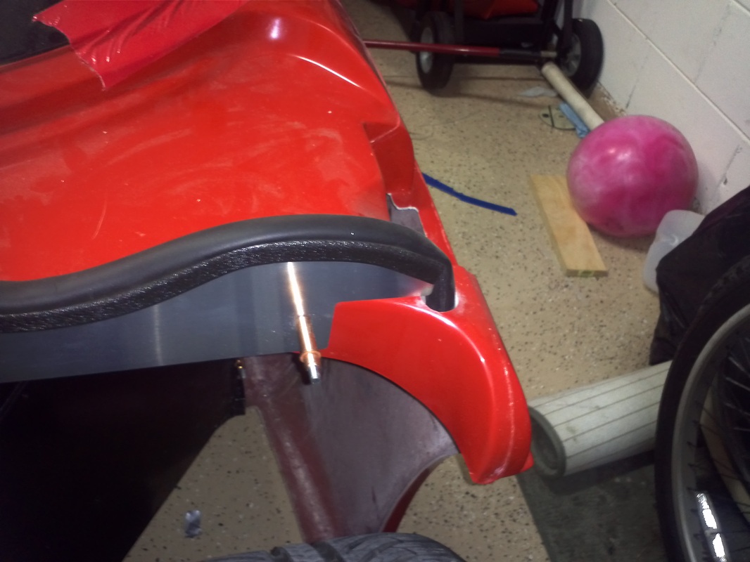
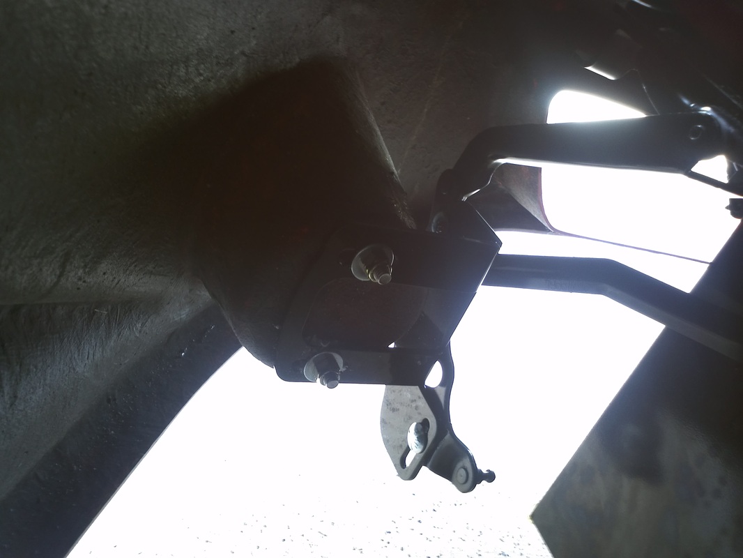
Door Strikers
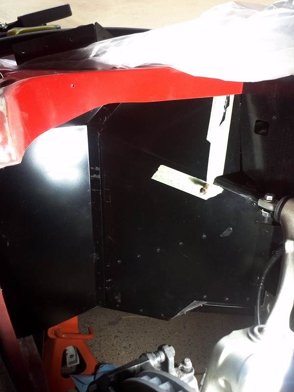
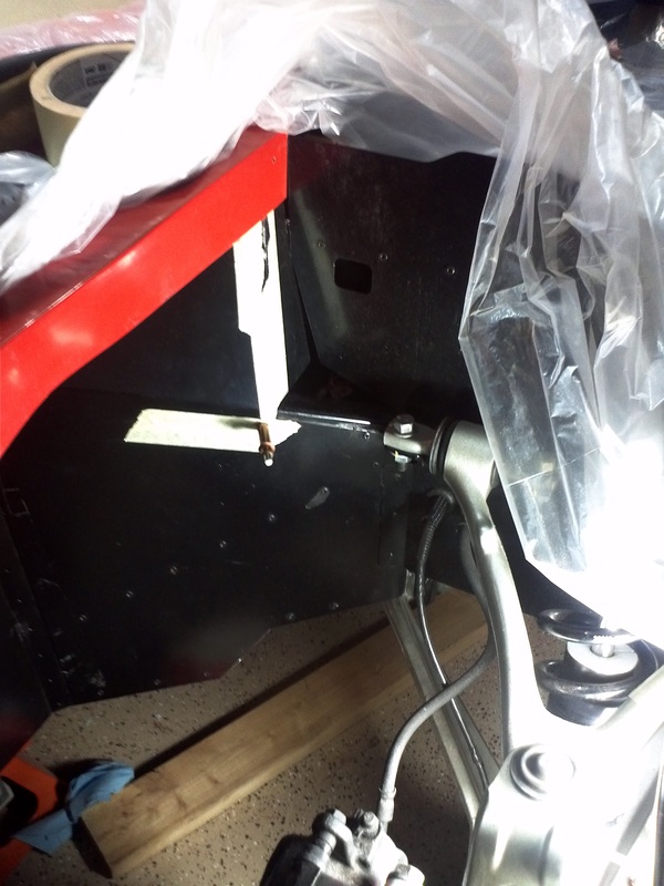
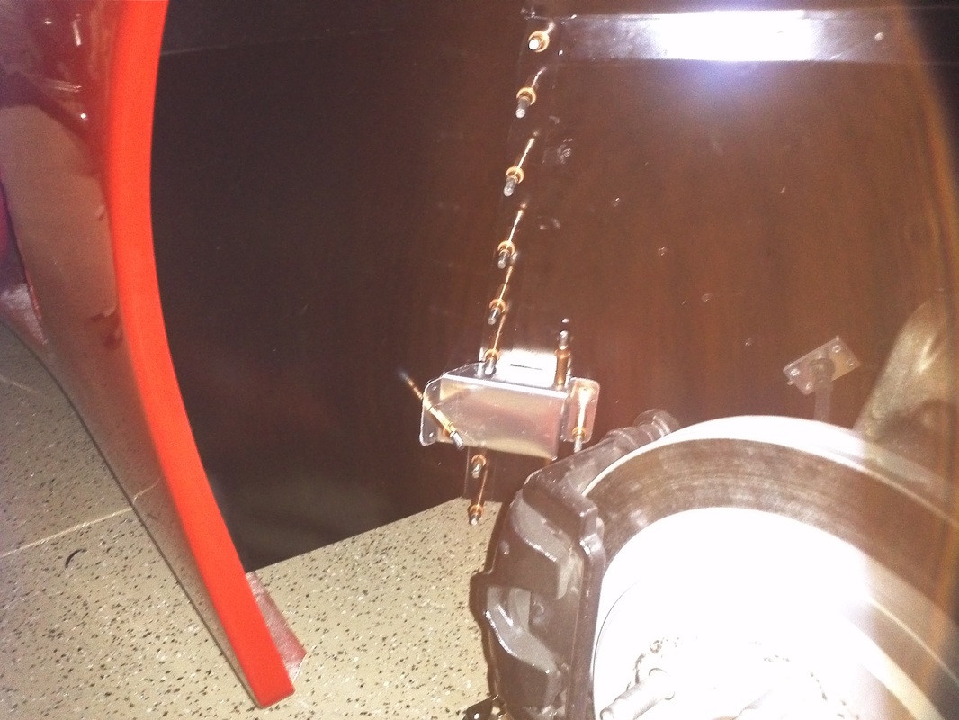
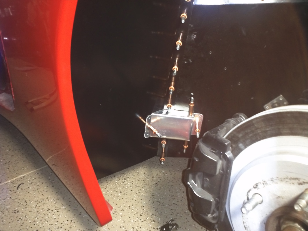
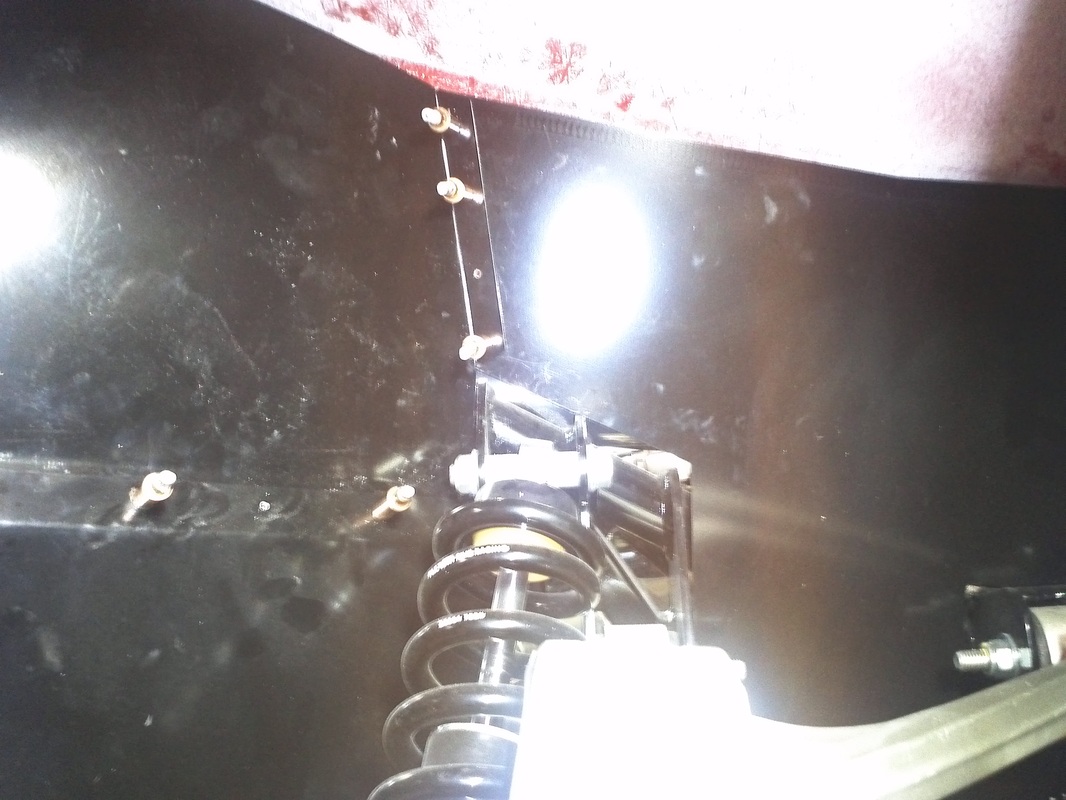
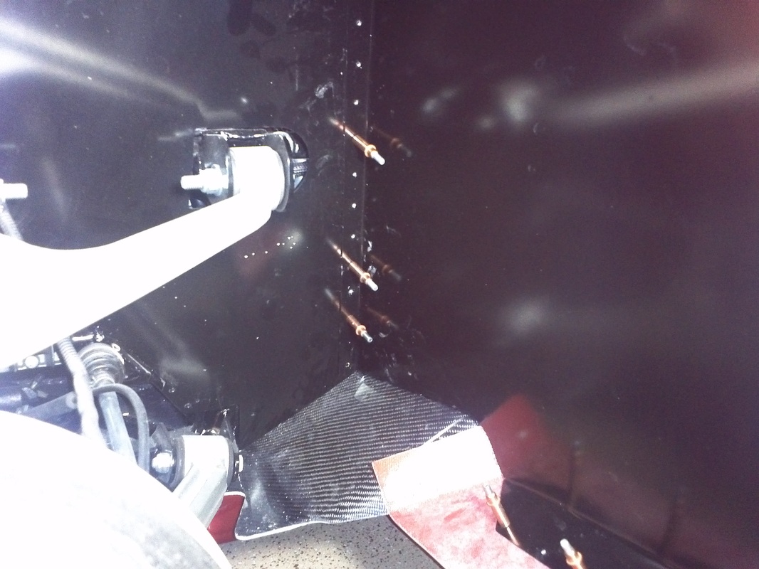
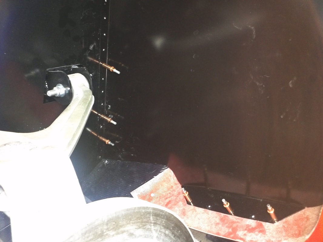
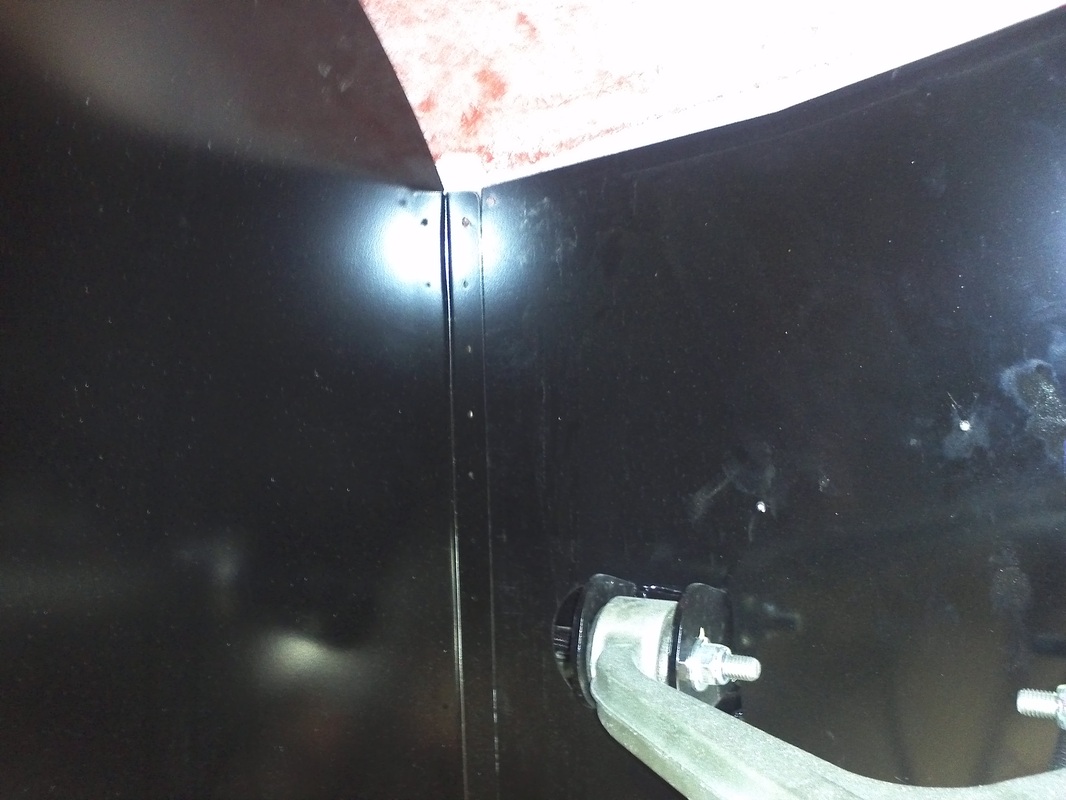
While I wait for the Roof/Halo issue to be resolve I am holding off on the final fitment of the doors. Because of the known passenger side gap between the body and frame in the door striker area the supplied door striker is too short to function. My solution is to fabricate a new striker. I did this by purchasing a set of 2.5" long 3/8" bolts, a .5" OD steel tube, some 3/8" fender washers and some 3/8' nuts. I placed the blot in place to get the length need. I subtracted the fender washer's thickness and used my pipe cutting tool to cut the steel pipe. I also used the cut off wheel to cut the head of the bolt down to match the original strikers. I fabricated a striker for the driver's side as well. You have enough adjustment on the driver's side to make the included striker work, but then it wouldn't match the other. For the purpose of testing the striker on the passenger side I put a .5" nut in the gap so that I could tighten the striker. I will fill this area with fiberglass reinforced filler added to the body. I also increased the hole in the striker mount to .5" and am using a washer/nut to secure the striker. This will give greater adjustment. From another Gen2 builder that has installed his passenger side window without redoing the door frame; you need more adjustment of the door latch toward the center of the GTM in order for the frame to work with the window without modification. This requires that the striker carry the same ability for adjustment.

Side Scoop Louvers
Side scoop Louver opening cut and louvers mocked up.


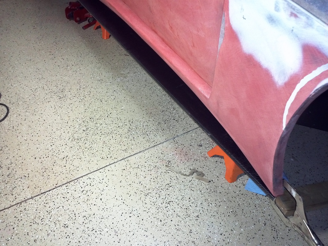
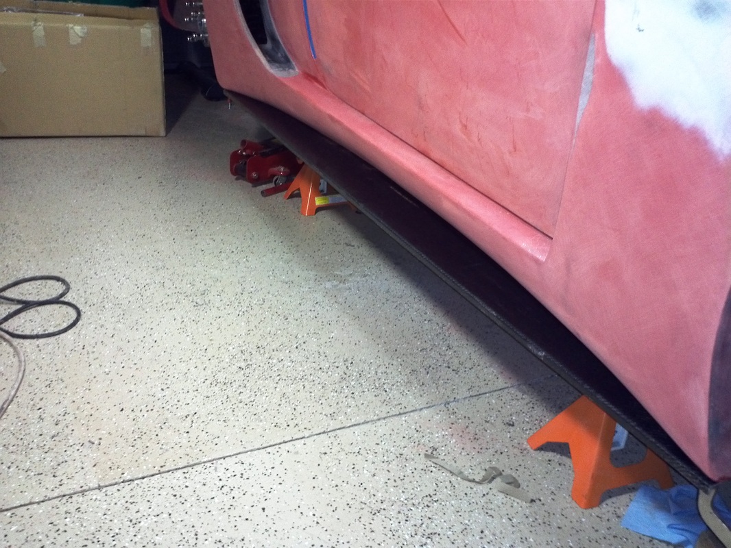
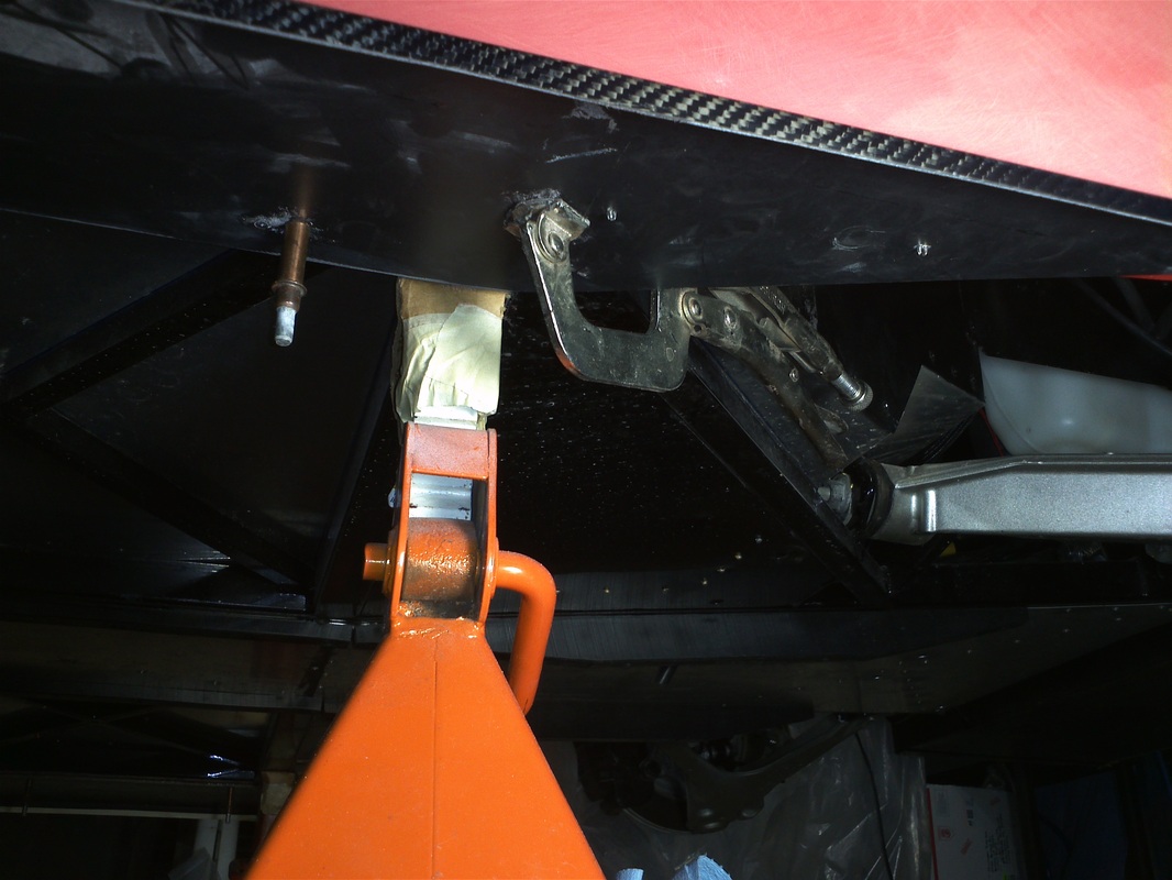
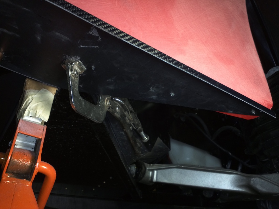
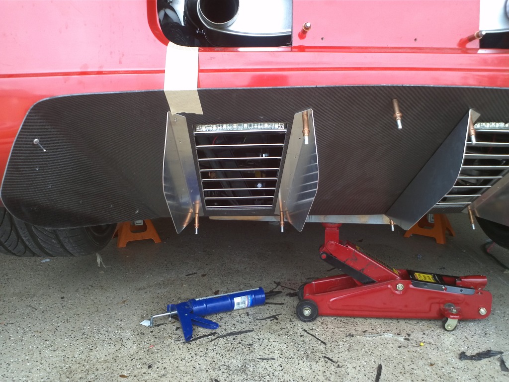
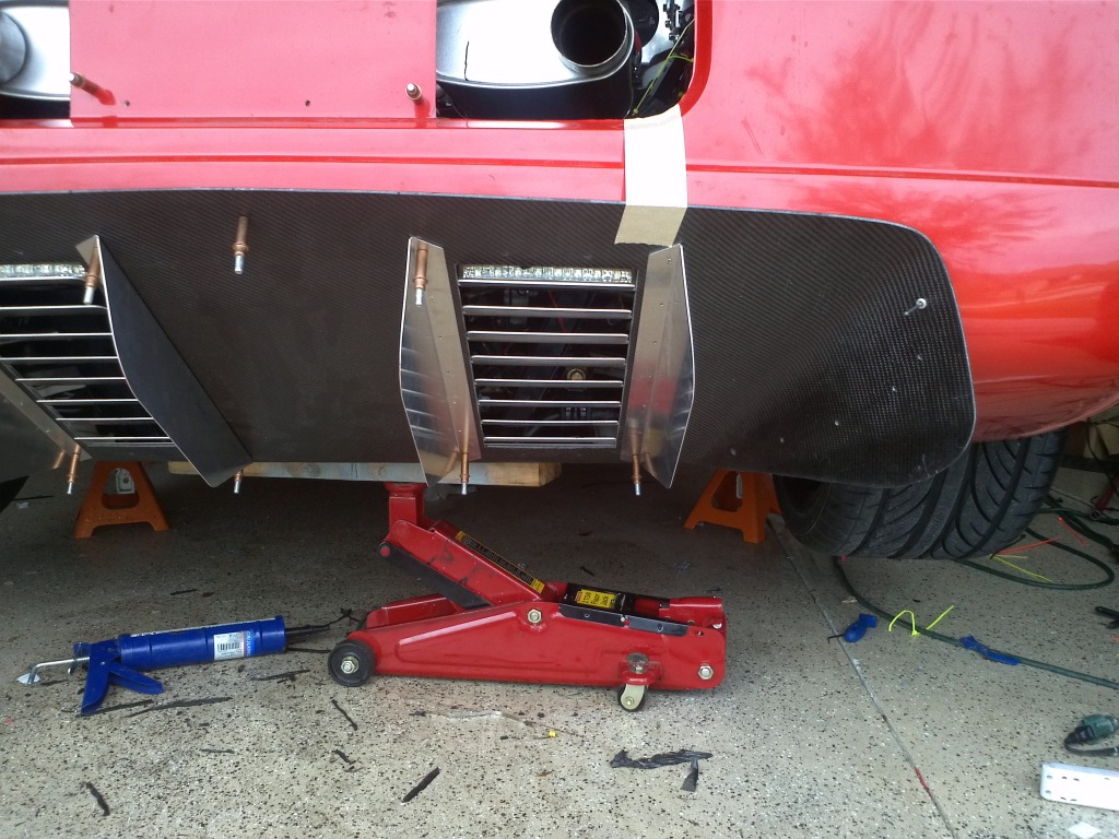
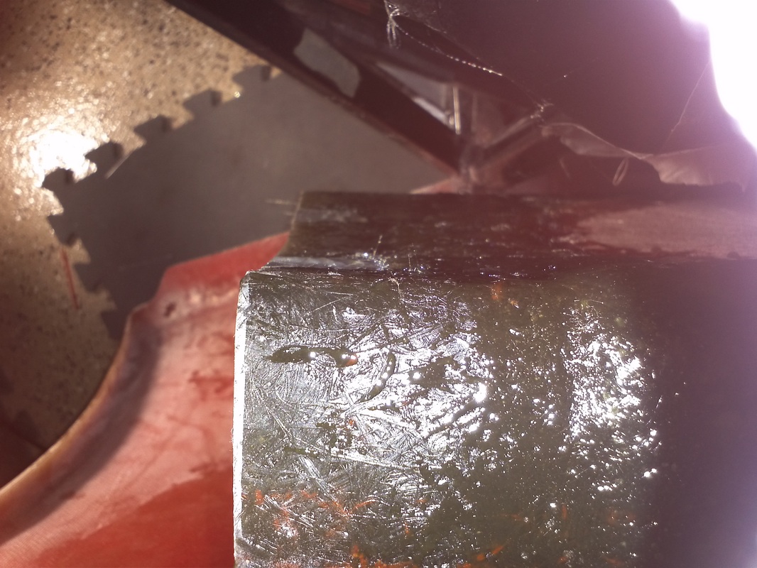
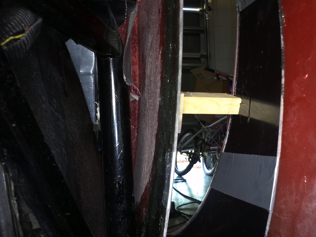
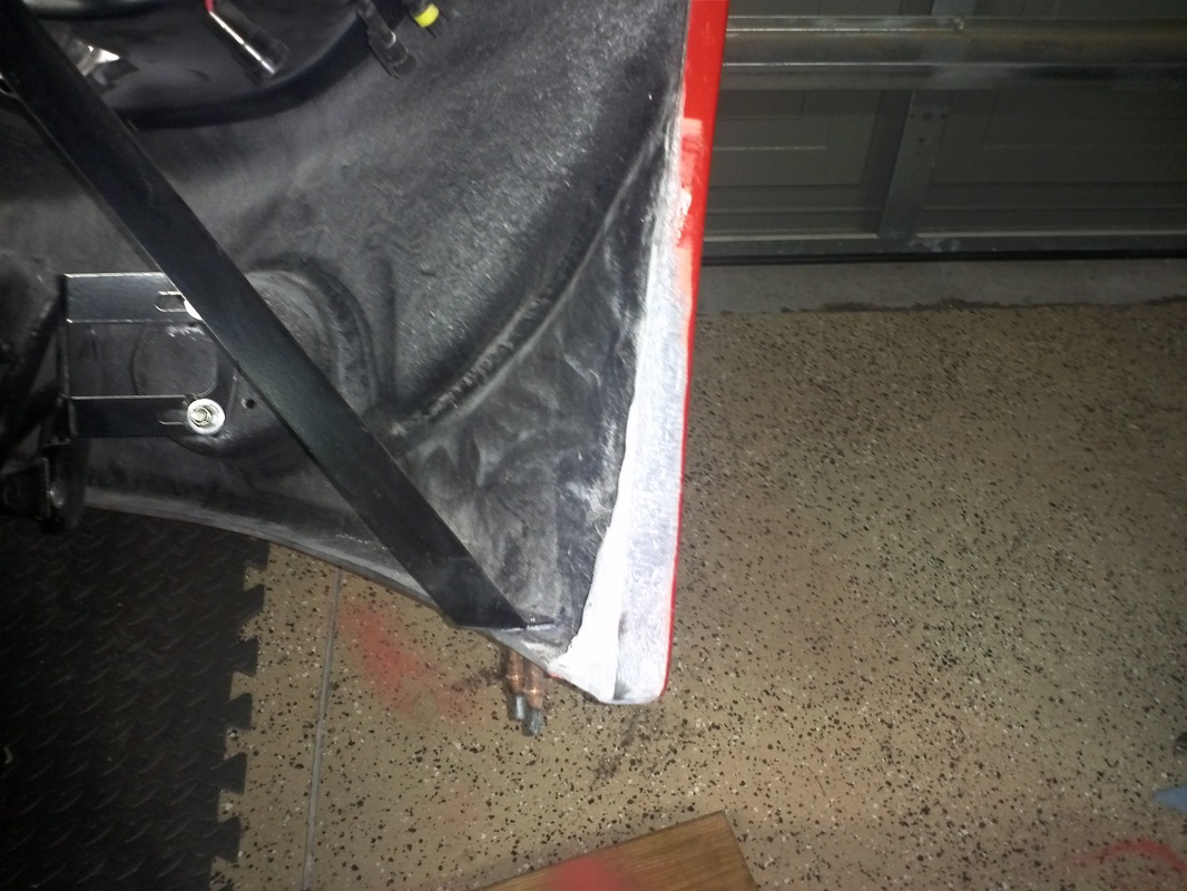
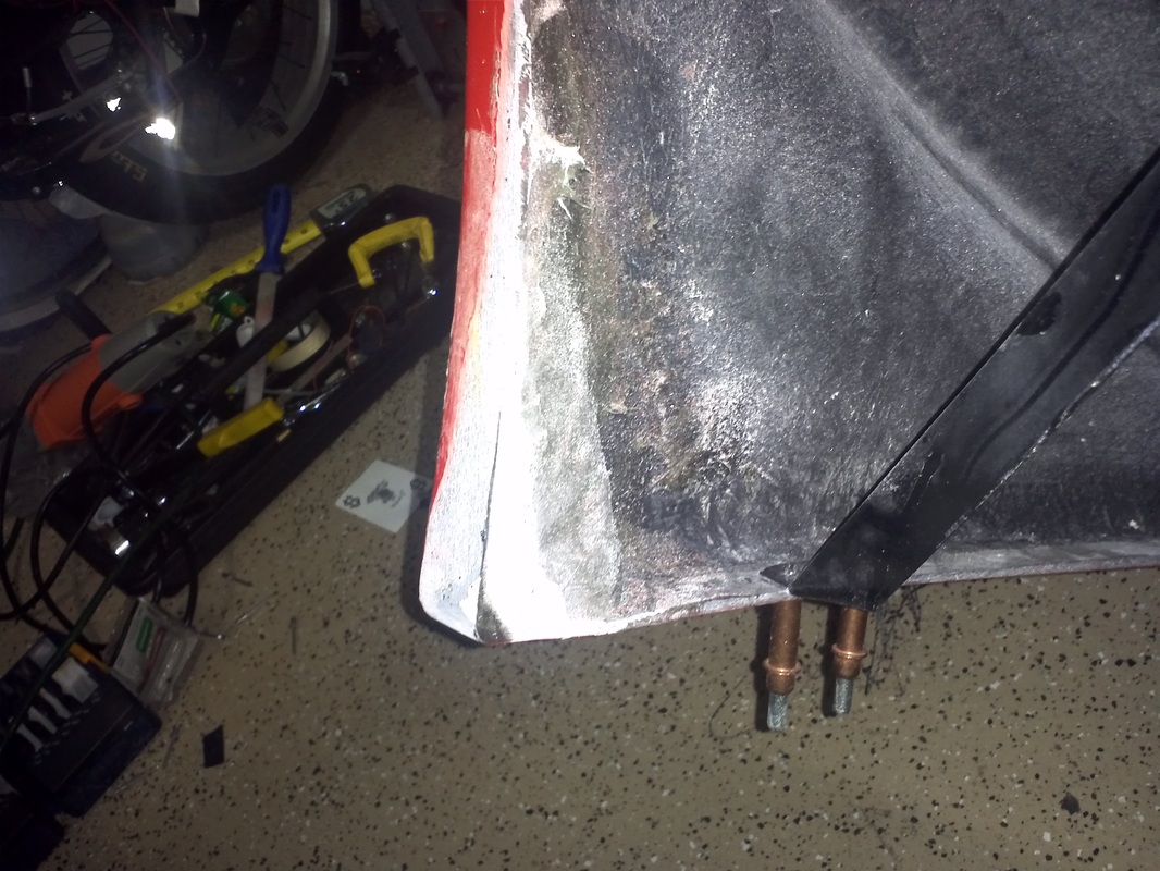
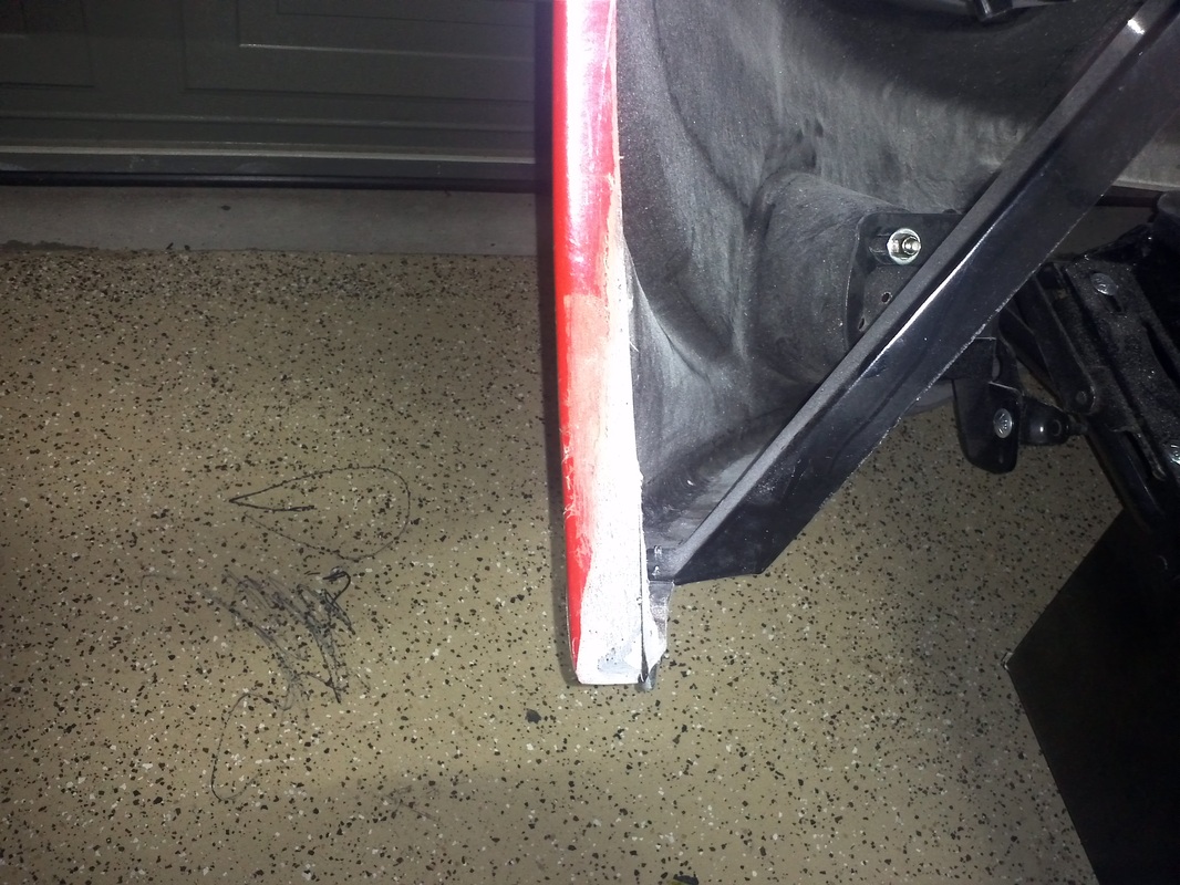
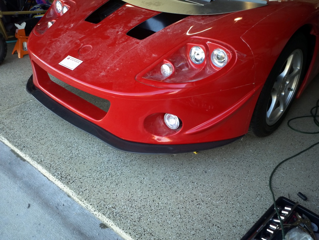
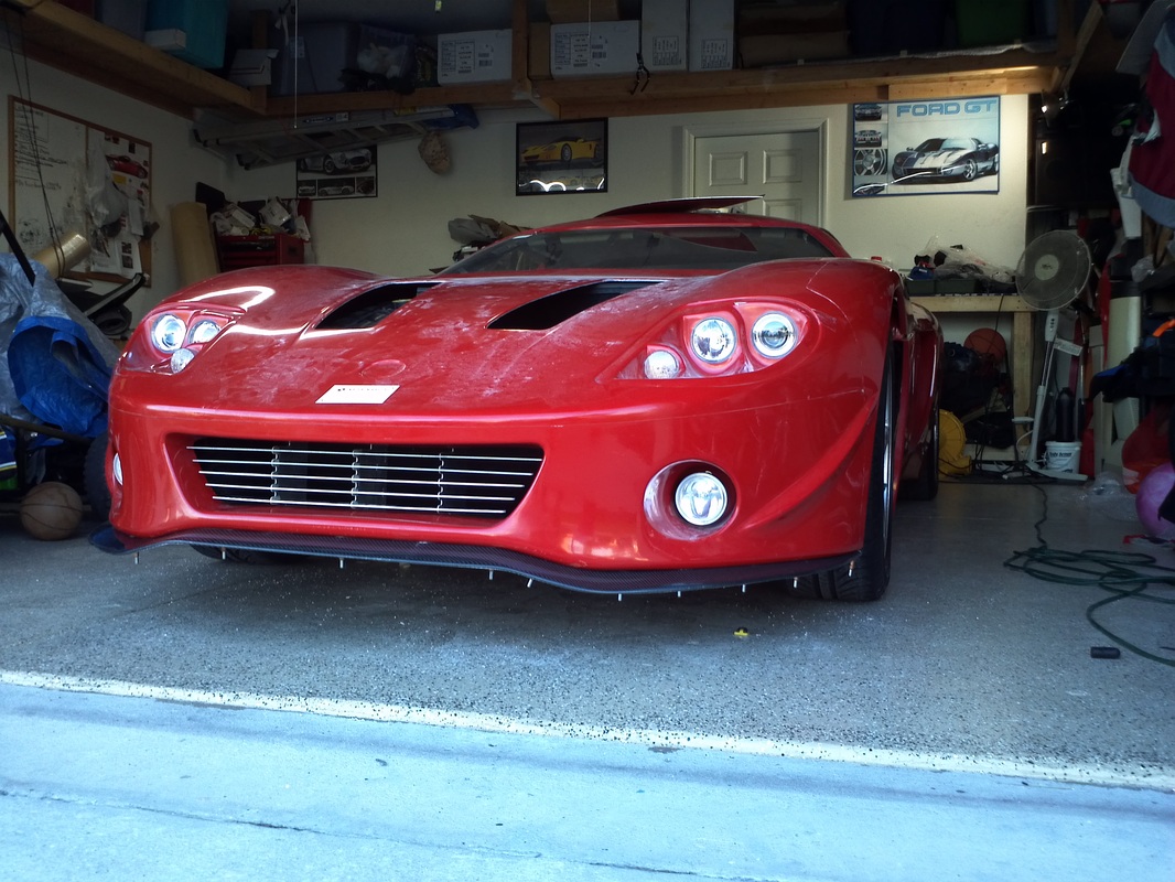
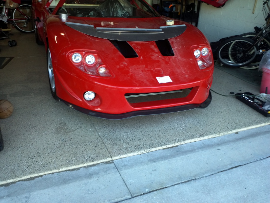
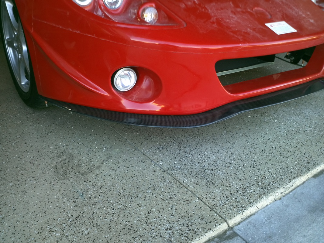
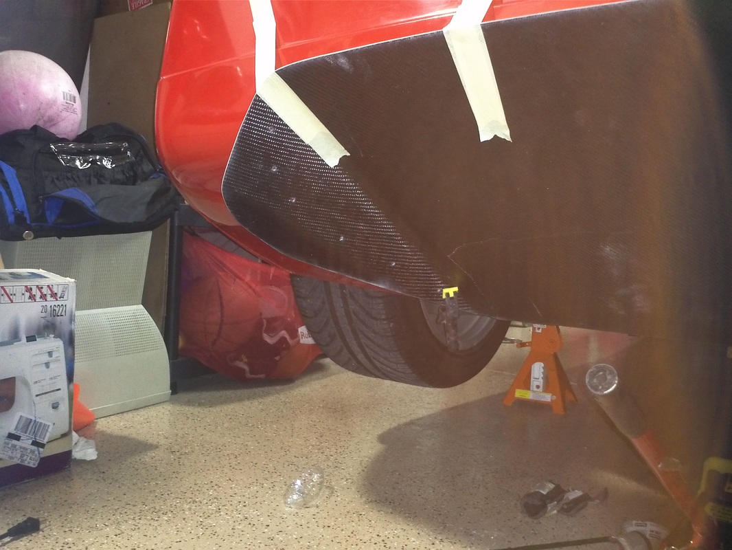
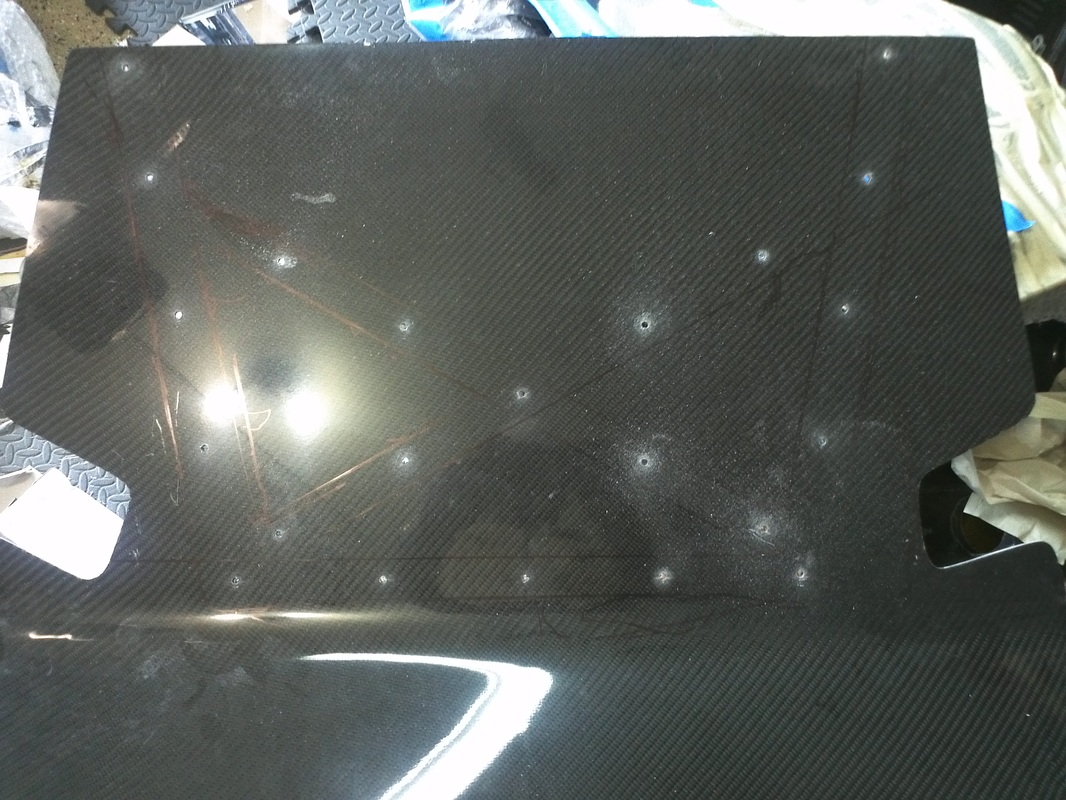
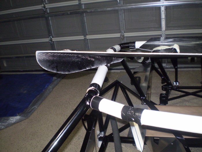
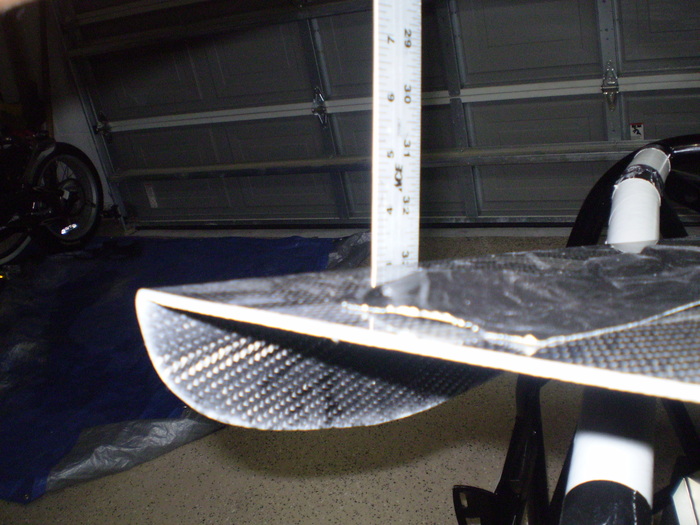
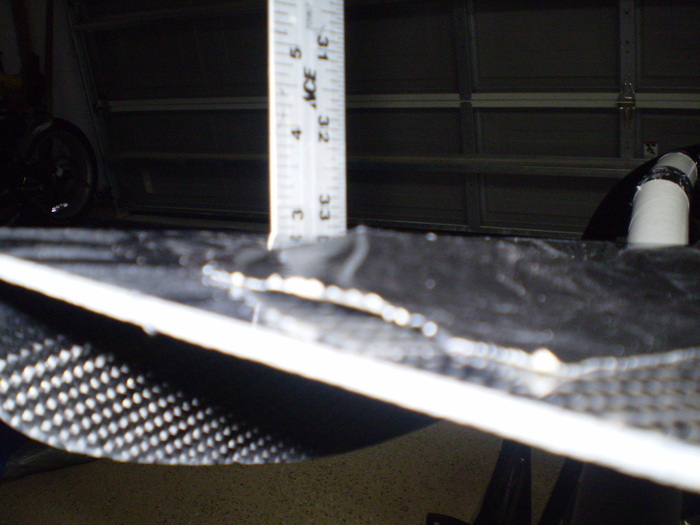
Carbon Fiber Splitter
Fit perfectly. I plan to put this idea on the forums for comment to see if its a good or bad idea and go from there. The plan is to add some 1/8. 3/16 or 1/4" bar stock strips that span from front to back under the the splitter along with some bar stock on the inside of the body. I am hoping that this will help maintain the intergrety of the spitter in case of a unforseen rub/dump. I believe that this would keep the splitter intact while putting all of the stress on the body. So if the bump was enough to cause damage it would be cheaper to repair the car in that area compared to the $400 cf splitter. ?????


Overall Body Progress Pics. First Set.


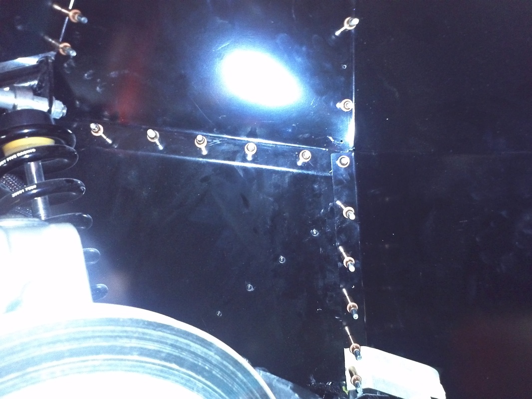
Wheel Well Close out Panels
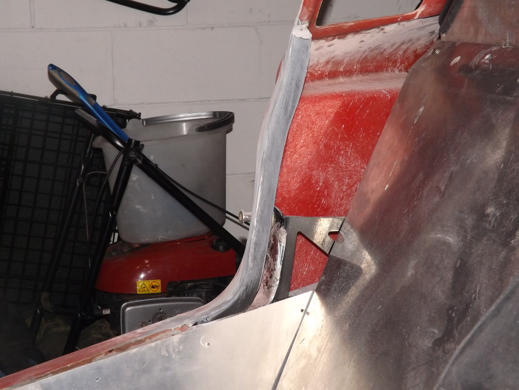
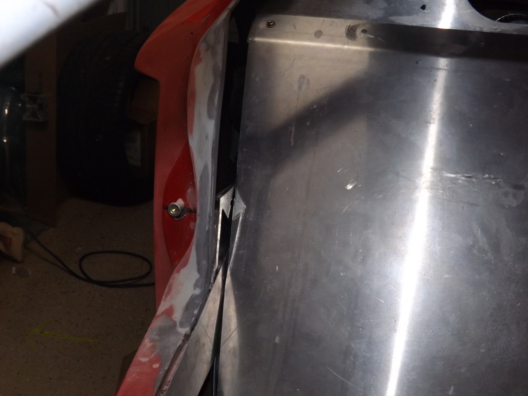
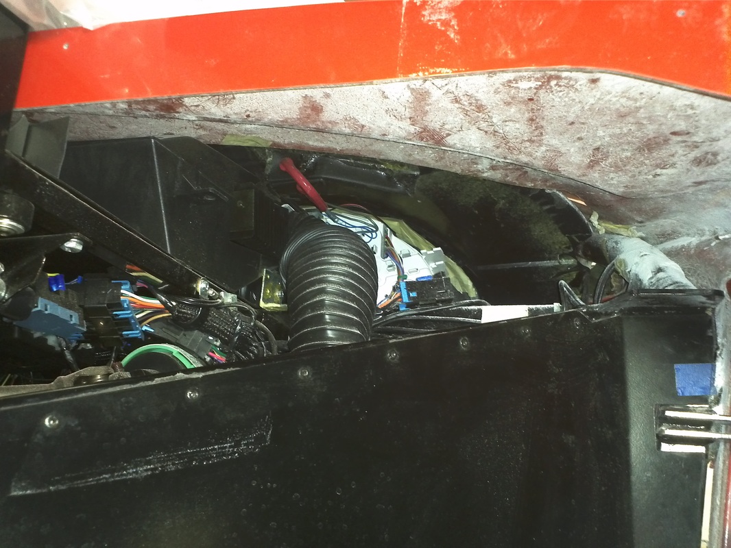
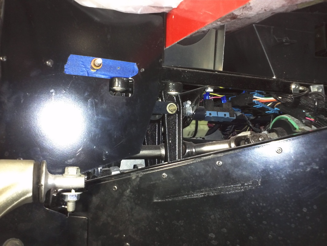
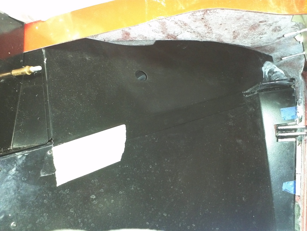
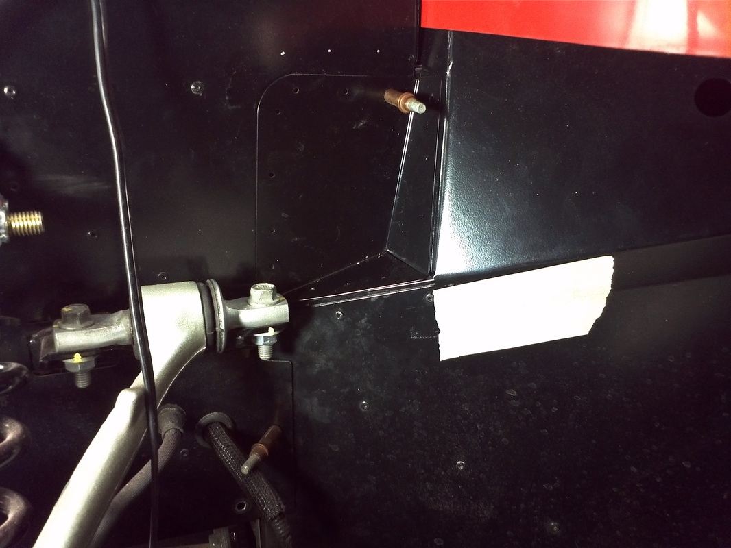
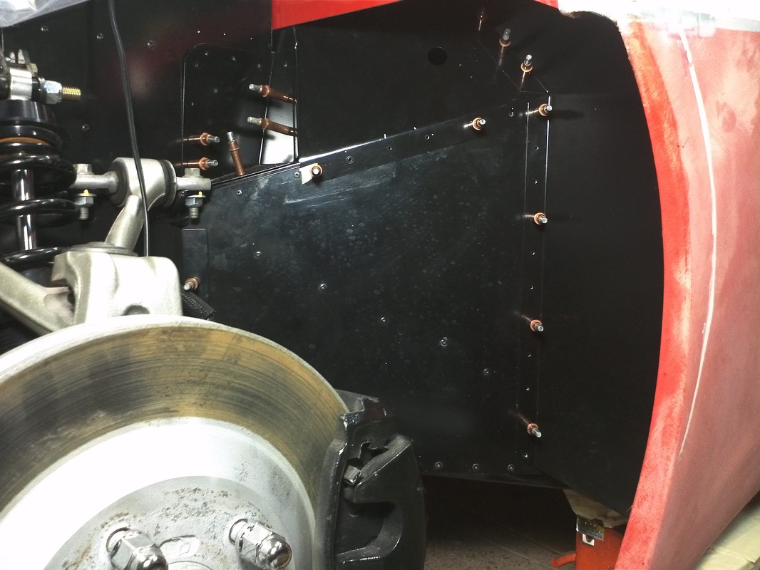
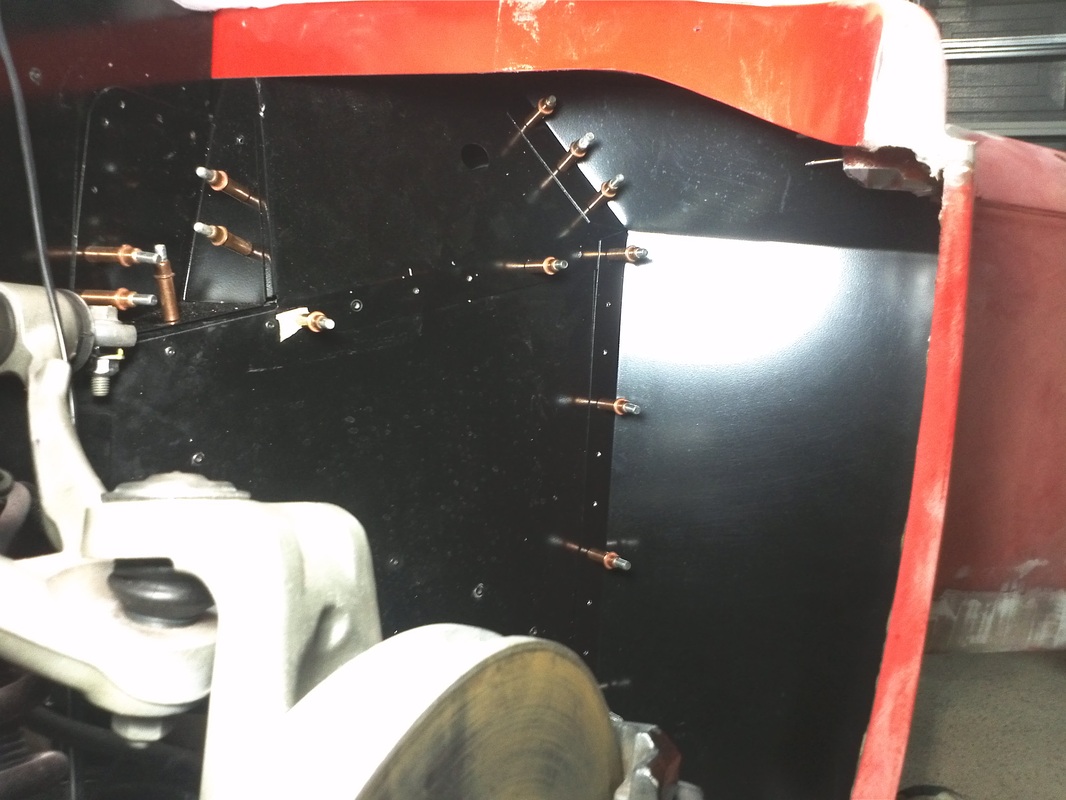
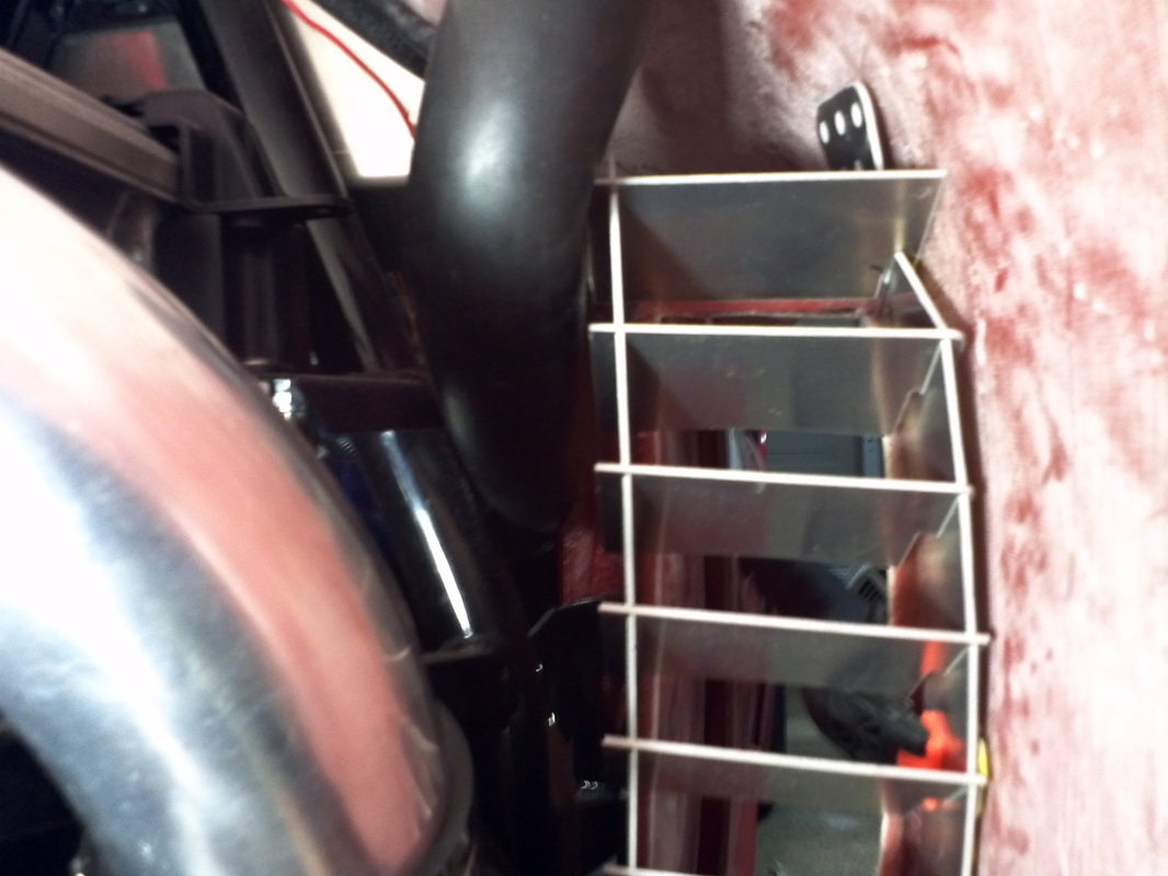
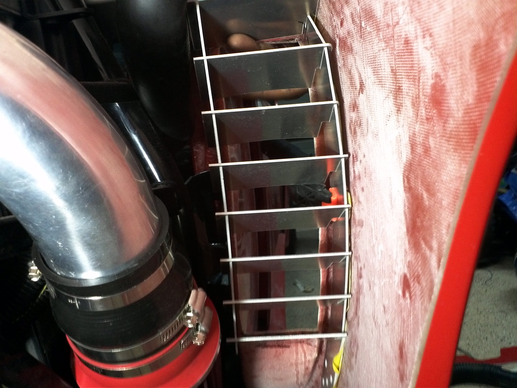
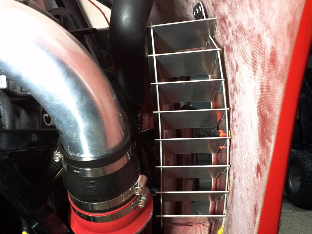
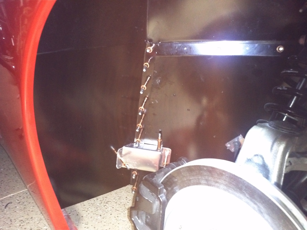
I'm putting all panels in as if the car was painted and it was the final installation. This way I can make adjustments and know that and how everything fits. This adds time to the build but will payoff as I wont run into some of the issues others have who painted the body prior to fitting all of the panels. At first initial fitment the two forward panels do not seem to fit, however taking a little of the angle out of the forward panel and the bottom of the adjacent panel makes them fit very well. I did not put the bulb seal on and I removed the piece I had on the center panel. This way I was able to scribe the panels for the bulb seal for a good fit.
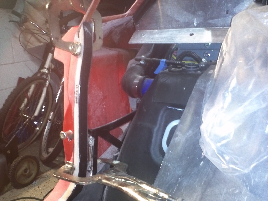
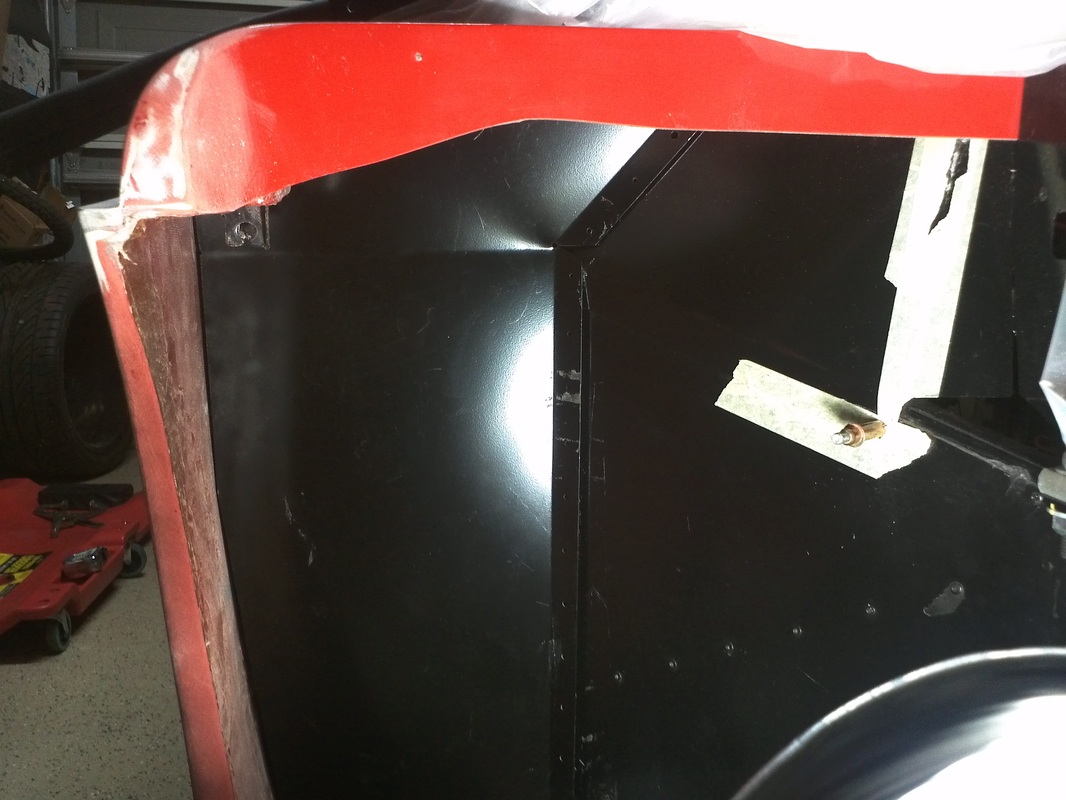
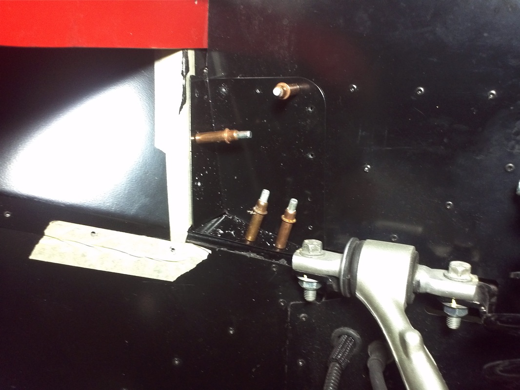
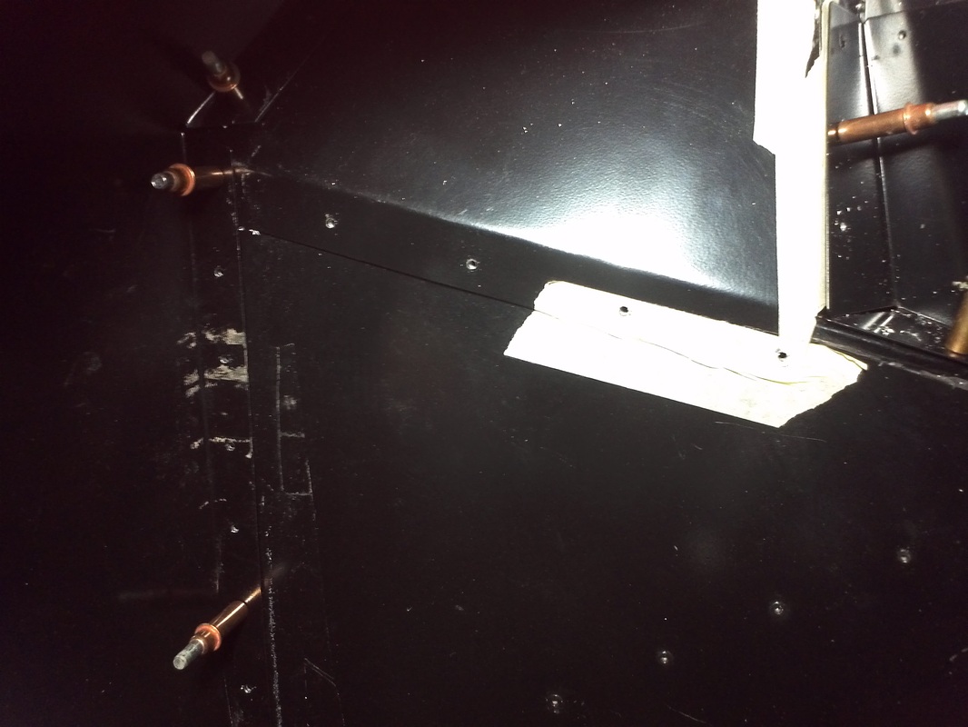
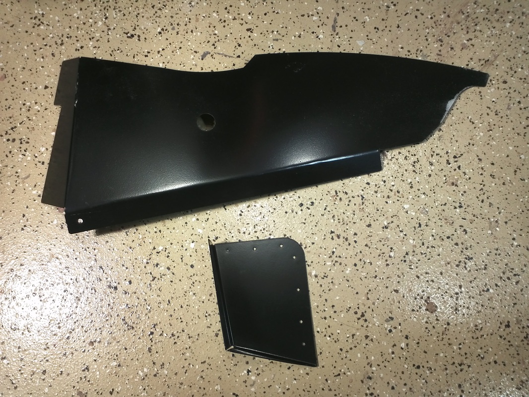
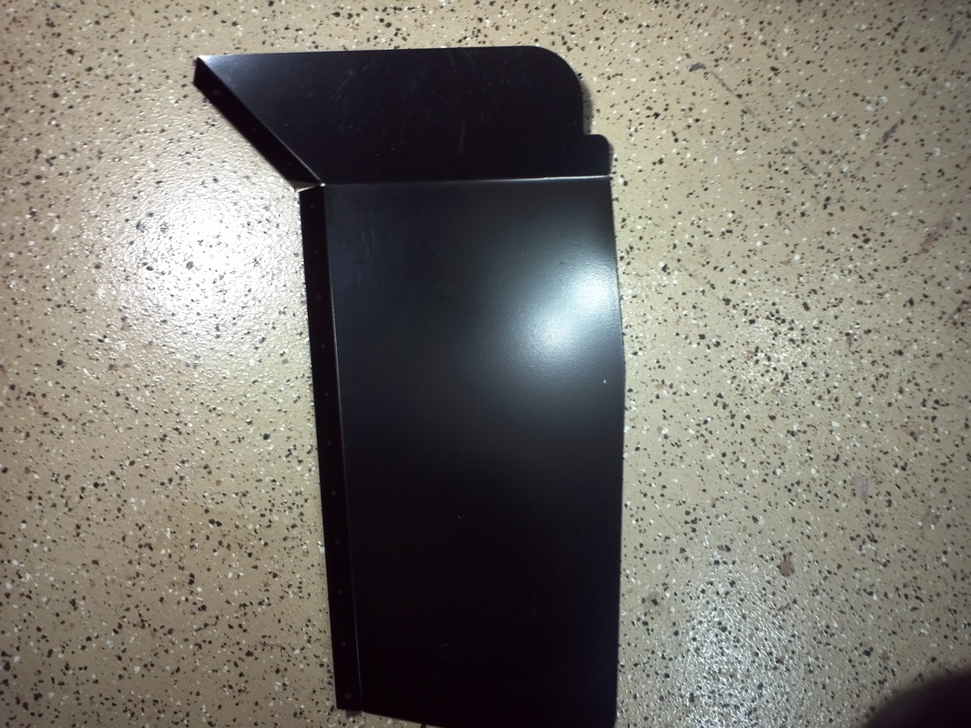
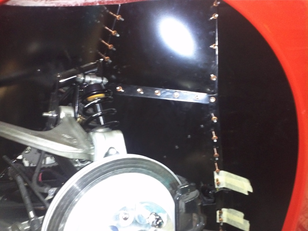
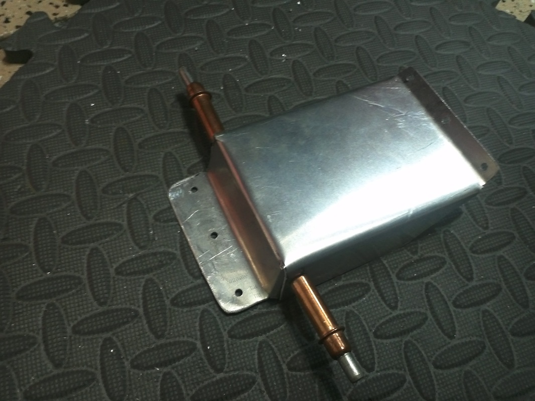
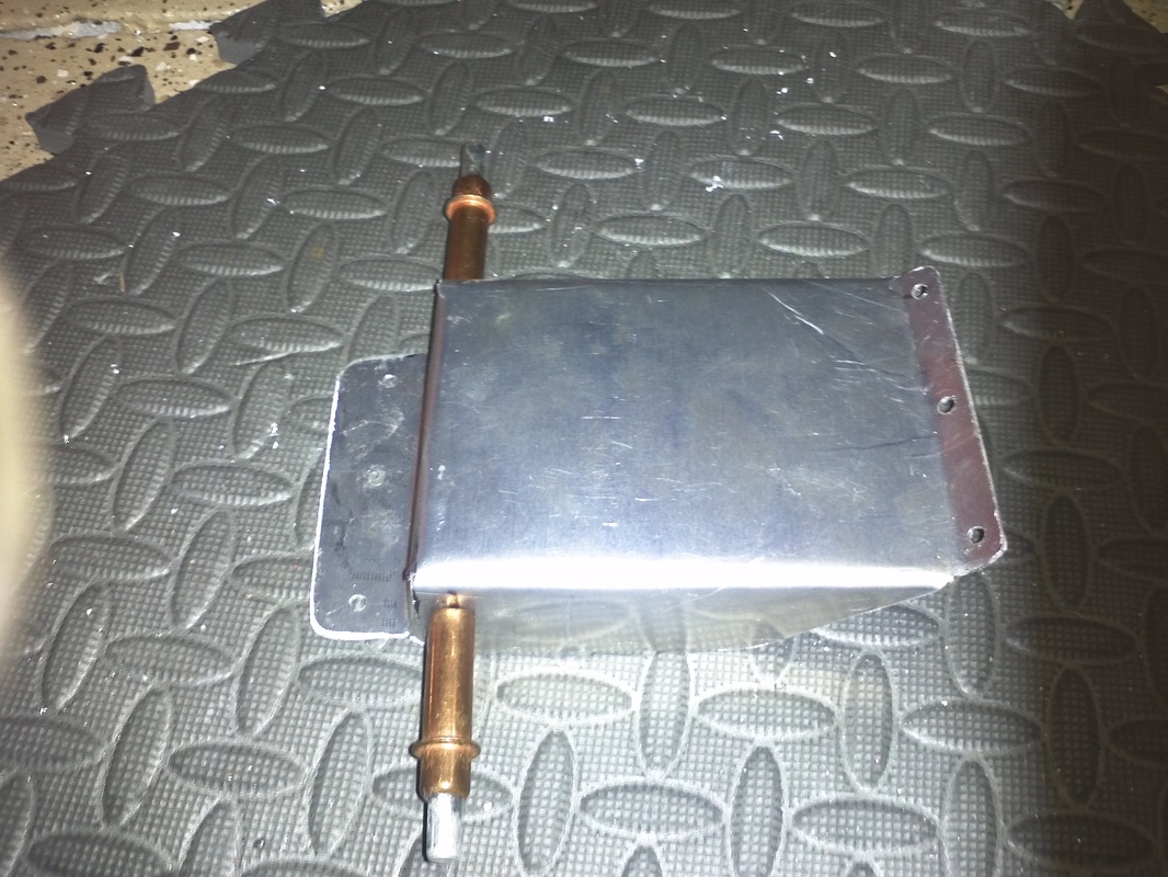
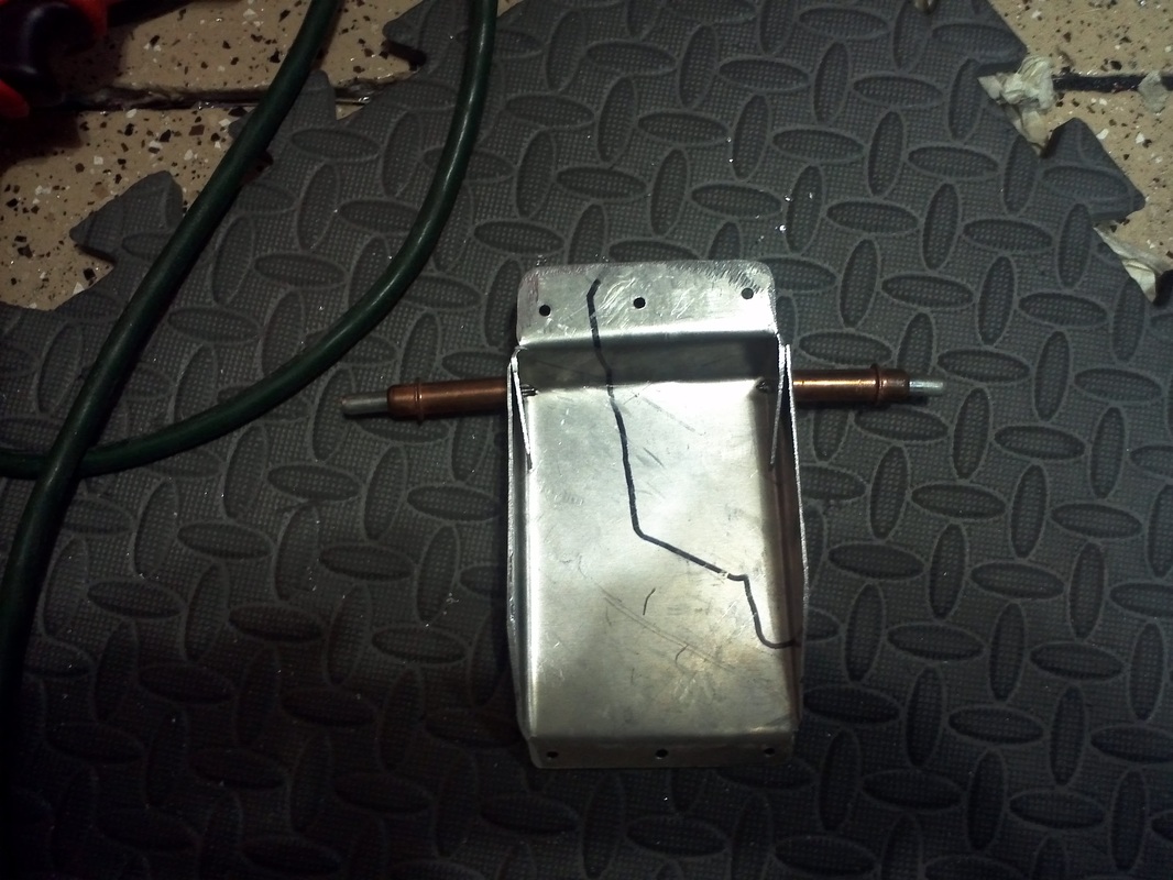
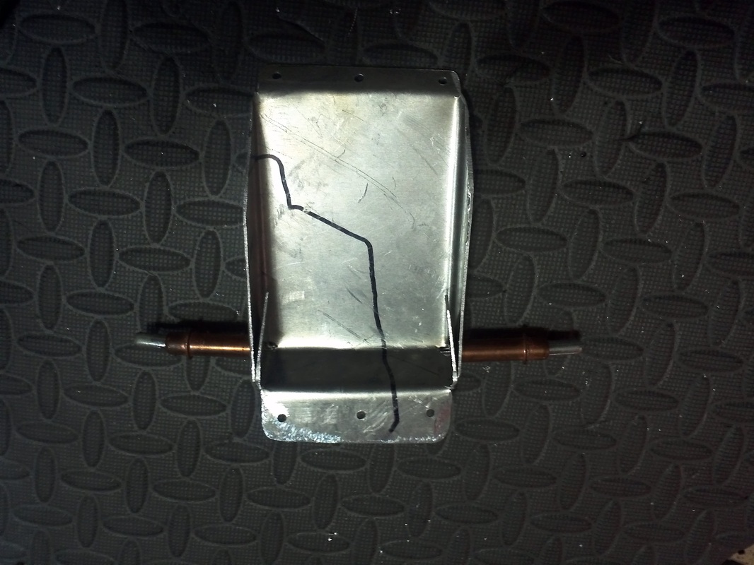
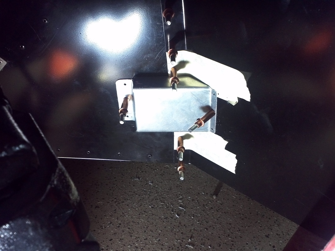
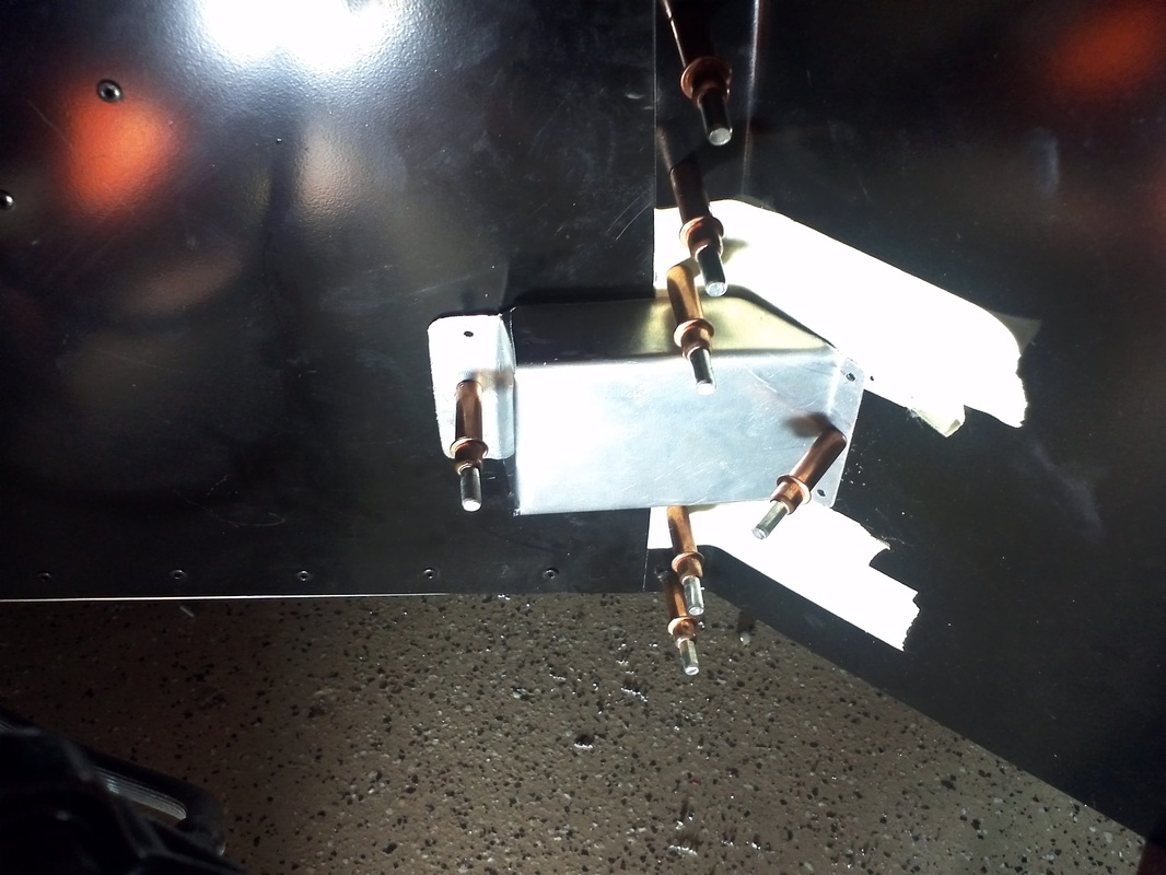
I also created my solution to the fuel tank crossover elbow issue. If you use the corvette fuel tanks and the crossover tube included in the kit you have to cut an opening in the panel for the elbow. In order to cover the area I took some cardboard and made a template that I den transfered to some 6061 aluminum. I cut it out with my jig saw and used my vise and had brake to make the bends. After that I trimmed it to fit. the. I'll have them powder coated on my next run.
I also created my solution to the fuel tank crossover elbow issue. If you use the corvette fuel tanks and the crossover tube included in the kit you have to cut an opening in the panel for the elbow. In order to cover the area I took some cardboard and made a template that I den transfered to some 6061 aluminum. I cut it out with my jig saw and used my vise and had brake to make the bends. After that I trimmed it to fit. the. I'll have them powder coated on my next run.


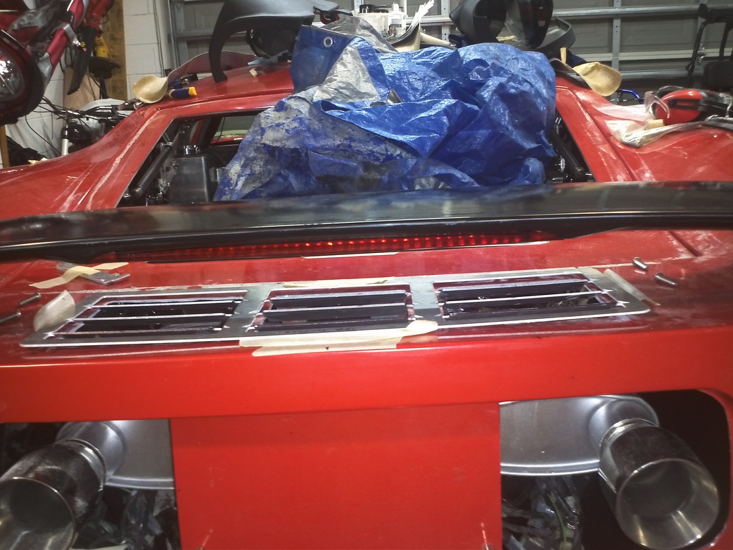
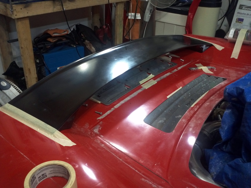
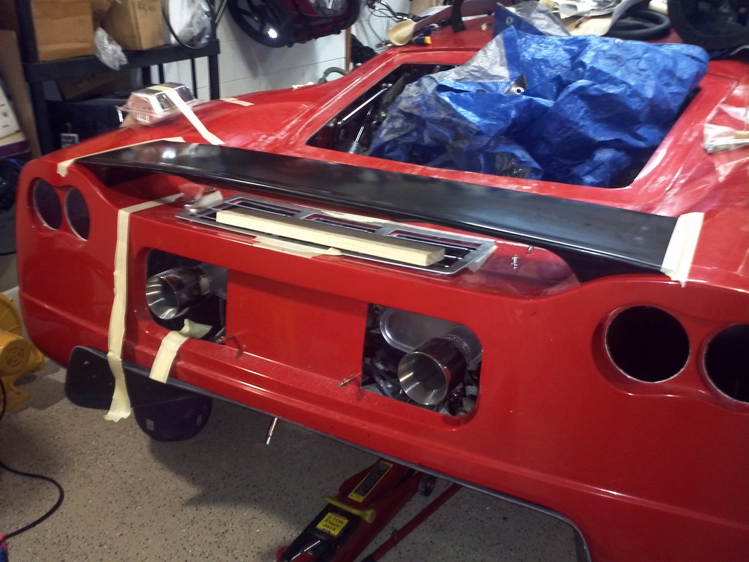
Custom Spoiler with integrated LED brake light.
This spoiler was made by hand by Thomas#142 from the forum. His original design was made specifically for the Gen1 and also provided a very secure aircraft grade duel latching system. He made a few modifications to his Gen1 design for fitment to the Gen2. The ends have a tapped metal insert and the spoiler is attached to the fenders for a clean and solid attachment. This spoiler is purely cosmetic and does not need a frame mounted attachment. If flows beautifully and looks production as if it was an original part of the kit.
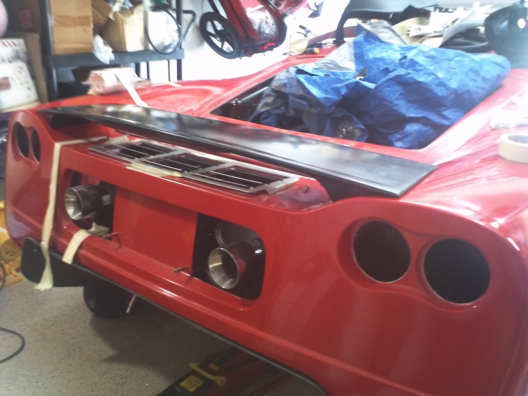
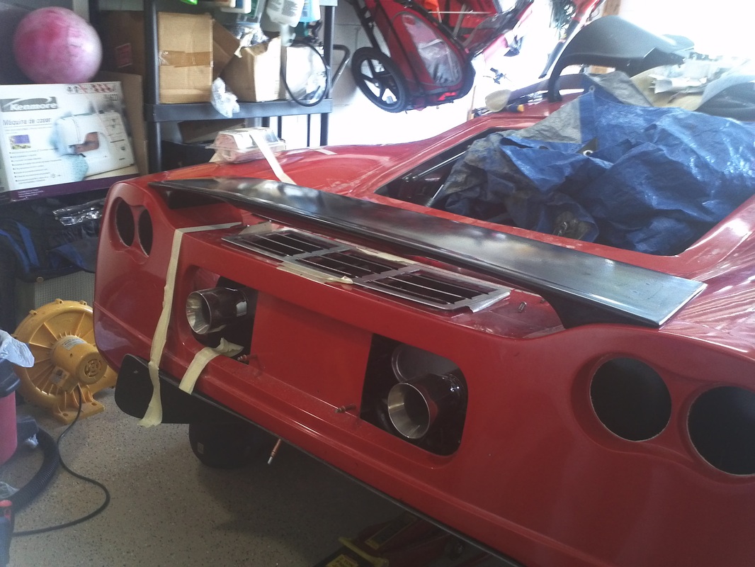
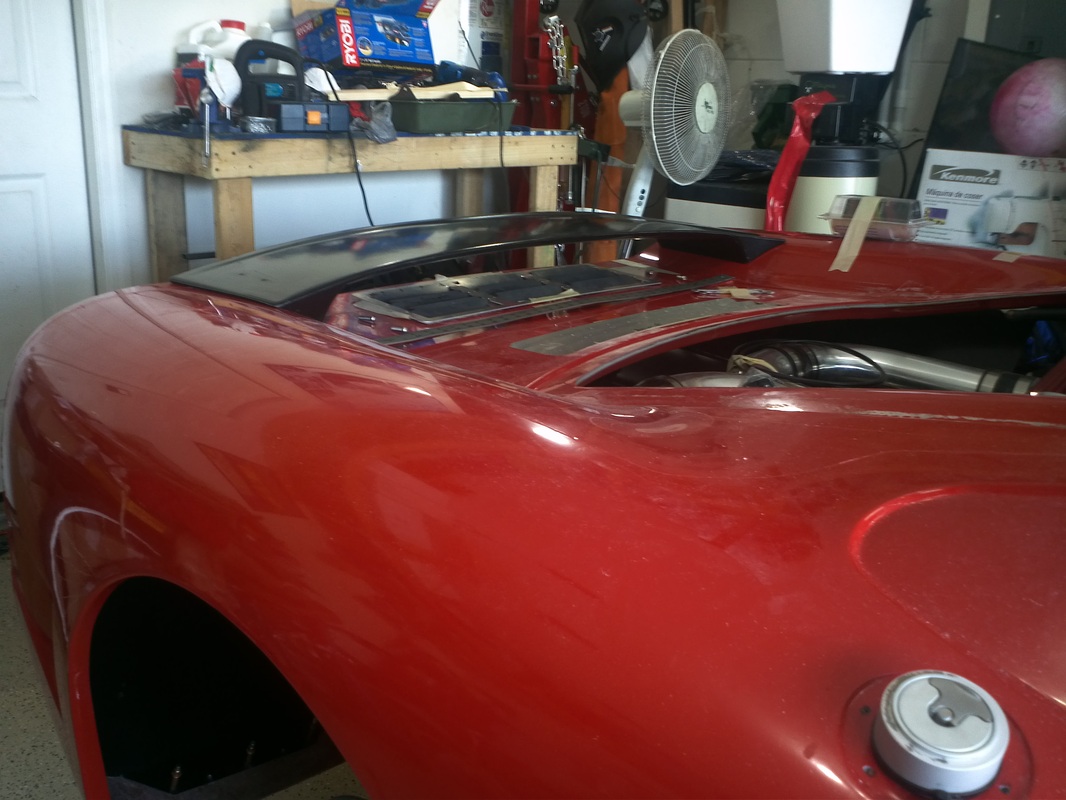
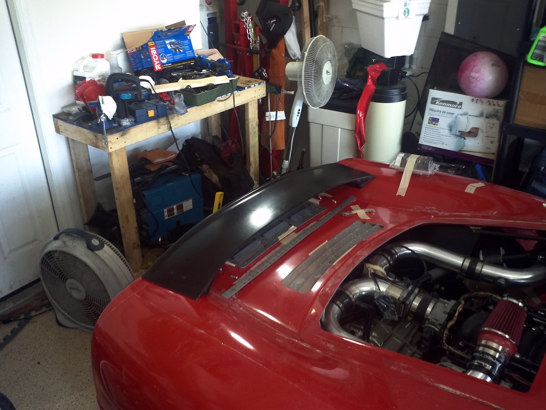
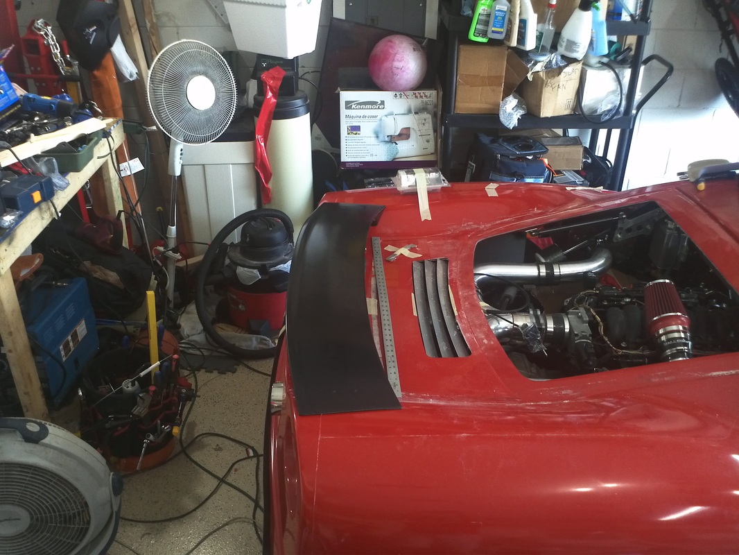
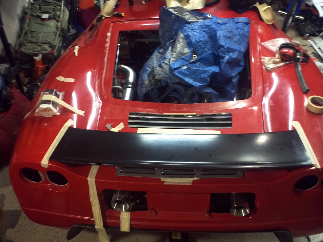
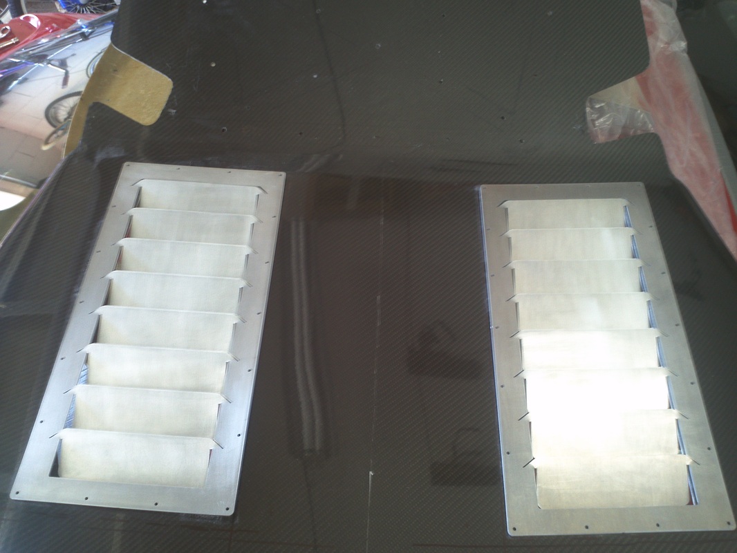
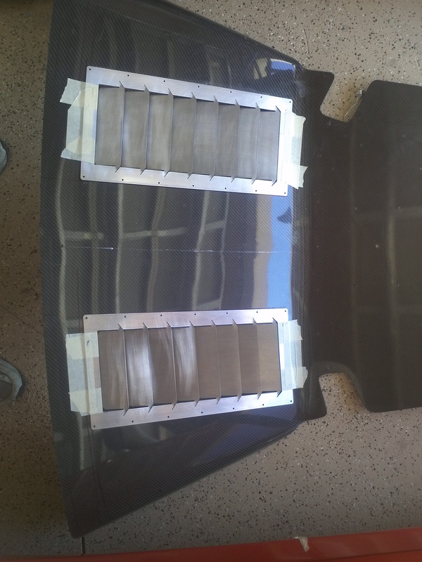
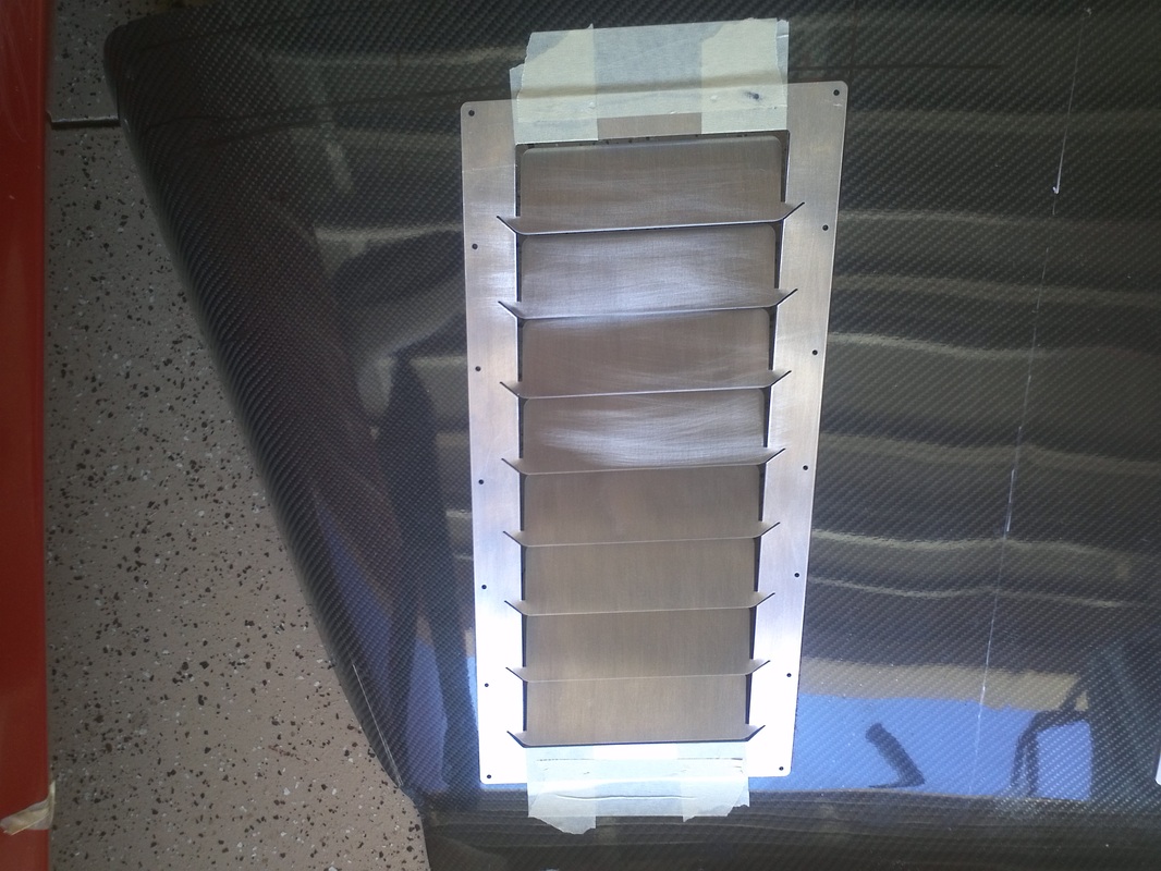
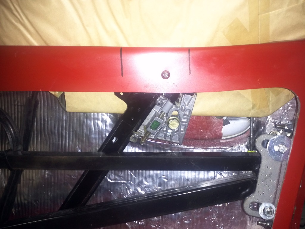
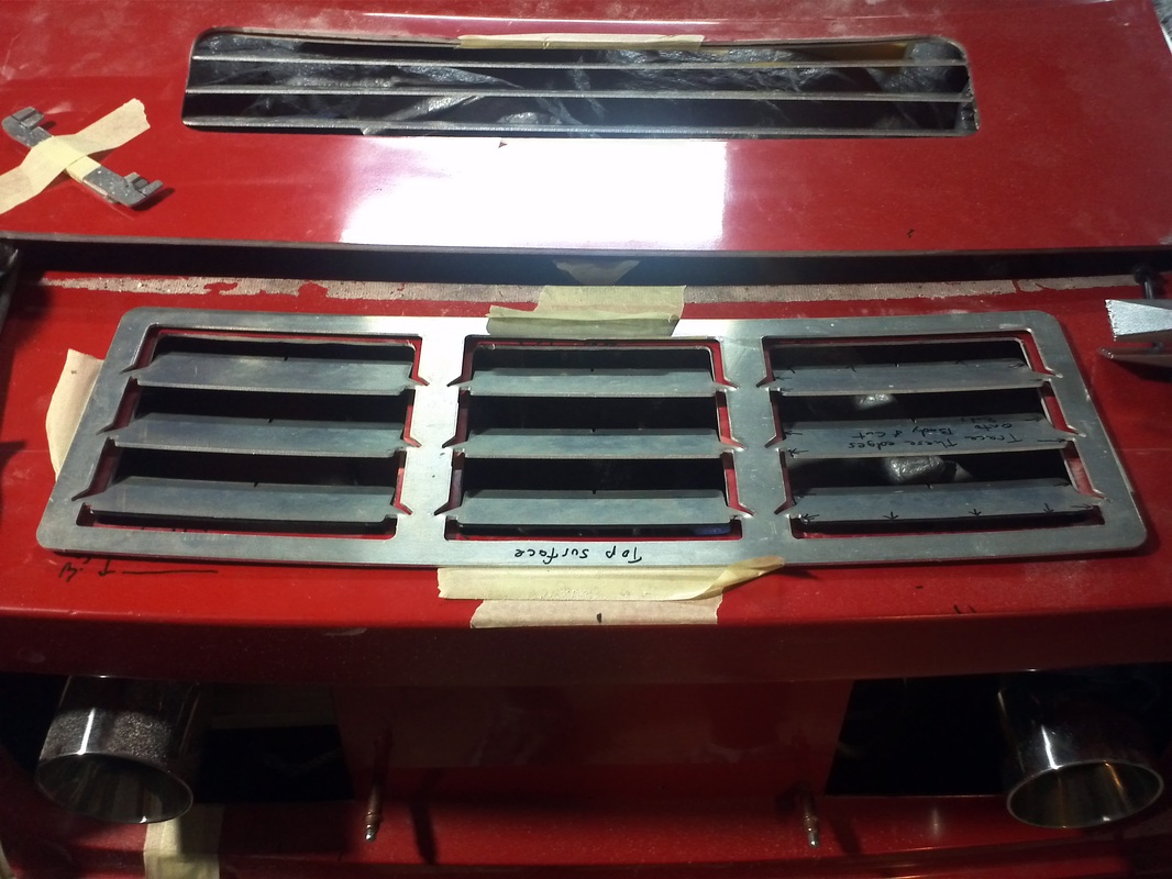
Hatch and Rear Deck Louvers and Electric Corvette Hatch Release and Striker
I centered the rear deck louvers and traced the louvers on to the deck. Then I connected the lines and used my electric body saw to cut the three openings. The fiberglass is about twice as thick on the rear of the openings so I will need to knock it down so that the louvers are flush in the rear. The opening for the hatch louvers is cut at the factory, but still needs to be sanded smooth. The rear deck louvers are installed from the bottom as with the others and both require assembling with the vertical pieces before powder coat and final install.
I used 1/16 plate steel to create a backing for the latch. It needs to be mounted much lower than the provided latch. I also added a 1" wide 1/8" thick brace to stiffen up the entire section. With the latch mechanism centered the striker section is offset to the passenger side of the car. I used the corvette hatch striker also. I had to remove 3/4" from the rear and will fill the void and have it powder coated with my next run.
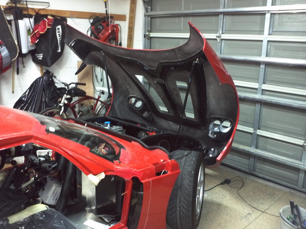
Body placed on chassis.
After rearranging and shifting boxes and more to the other side of my garage I backed the chassis in under the body that was mounted on the ceiling. I removed the nylon straps I had attached for extra hold and lowered the chassis down to the frame. I measured and marked the front door area and installed two clecos per side. I then lifted the rear to the required height which is about a half inch higher and the proceeded to measure from shock mount to center wheel well to ensure the body was centered. I had to move it to the passenger side just a bit.


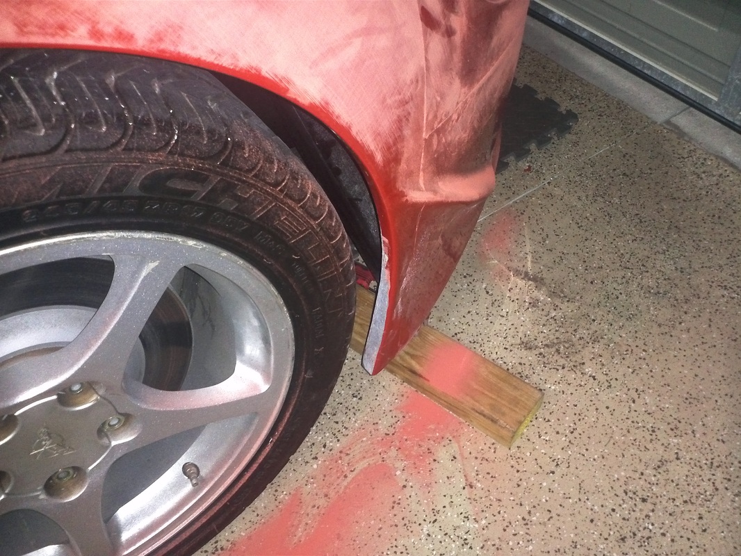
Ride Height (over 2" too high)
Once I had it outside the huge space in the top of each wheel well between the tire and the well jumped out at me. So I measured the current ride height. The manual says to adjust the ride height to 4.5". I am currently at 6.5" in the front and 6.35" in the rear. Once I adjust it down I expect the wheels to center nicely.
Gen1 Diffuser
Decided on using the Gen1 Diffuser.


Diffuser
The diffuser now differs from the Gen1 diffuser. It appears the two strakes are much shorter. The FFR Gen2 GTM has the the diffuser mounted with stand-offs running the length of the upper horizontal. The kit did not include any hardware to mount it in that fashion. I did talk to Jason at FFR and they are currently working this as well as the hatch latch. I was going to exchange this diffuser for a Gen1 version, but will hold off for now until I see what FFR comes up with for the mounting of this diffuser.

Diffuser Update.
I ordered one of the last two in stock Gen1 Diffusers form FFR after trying to fit the Gen2 to the body and seeing the results of builders at that stage. We were able to get their techs to install an actual Gen2 diffuser on their Gen2 because I and other Gen2 builders tried to fit it as FFR did with their Gen2. The Gen2 diffuser that is shipped with the Gen2 kits and the one that was on their Gen2 are different diffusers. Basically FFR modified a Gen1 Diffuser. The one included with the Gen2 is a completely different one. So when we tried to fit it as in the pictures of their Gen2 it didn't work. FFR tech’s instructions through the forum were to mount it on the sides and that the horizontal gap should be 2-3 inches. We quickly discovered that this diffuser could not be installed as stated. After FFR installed it on their Gen2 they discovered that the horizontal gap is 4 inches and that it was best if they supplied spacers to their customers. I'm still waiting on the spacers, but it's good to know that the Company will do what's required for its customers.
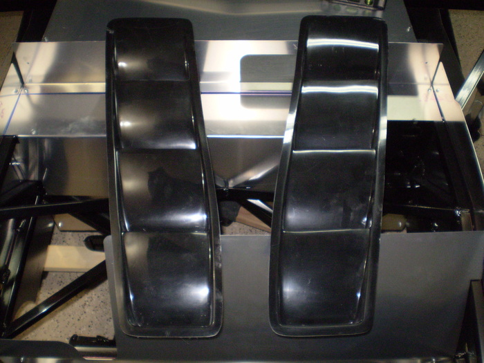
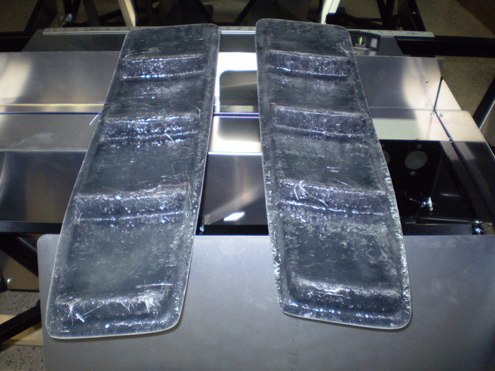
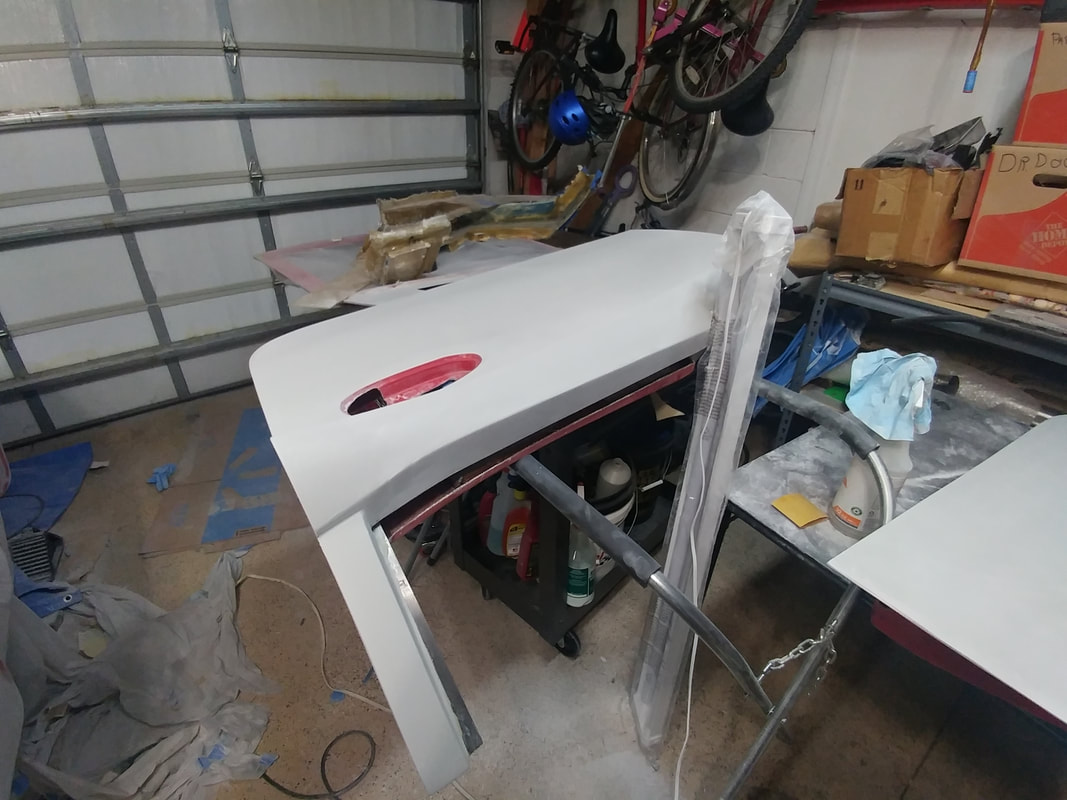
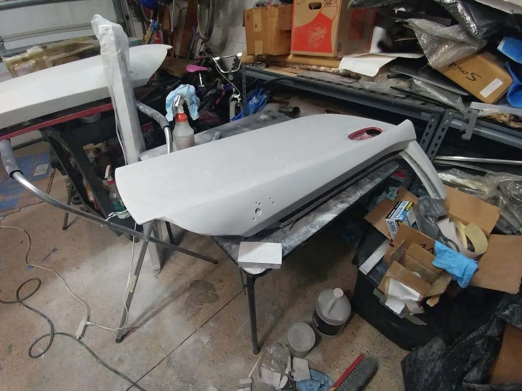
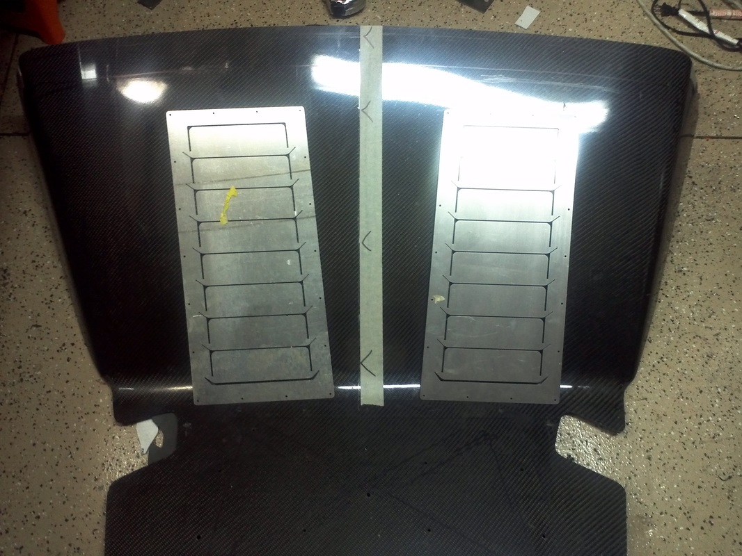
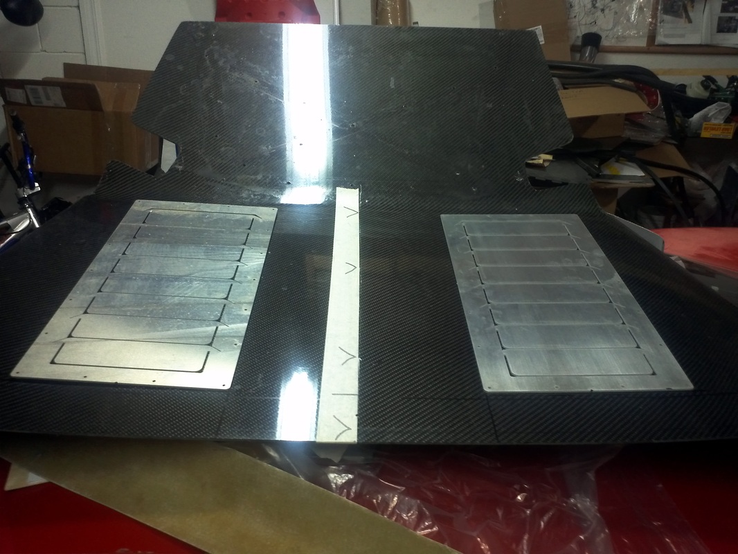
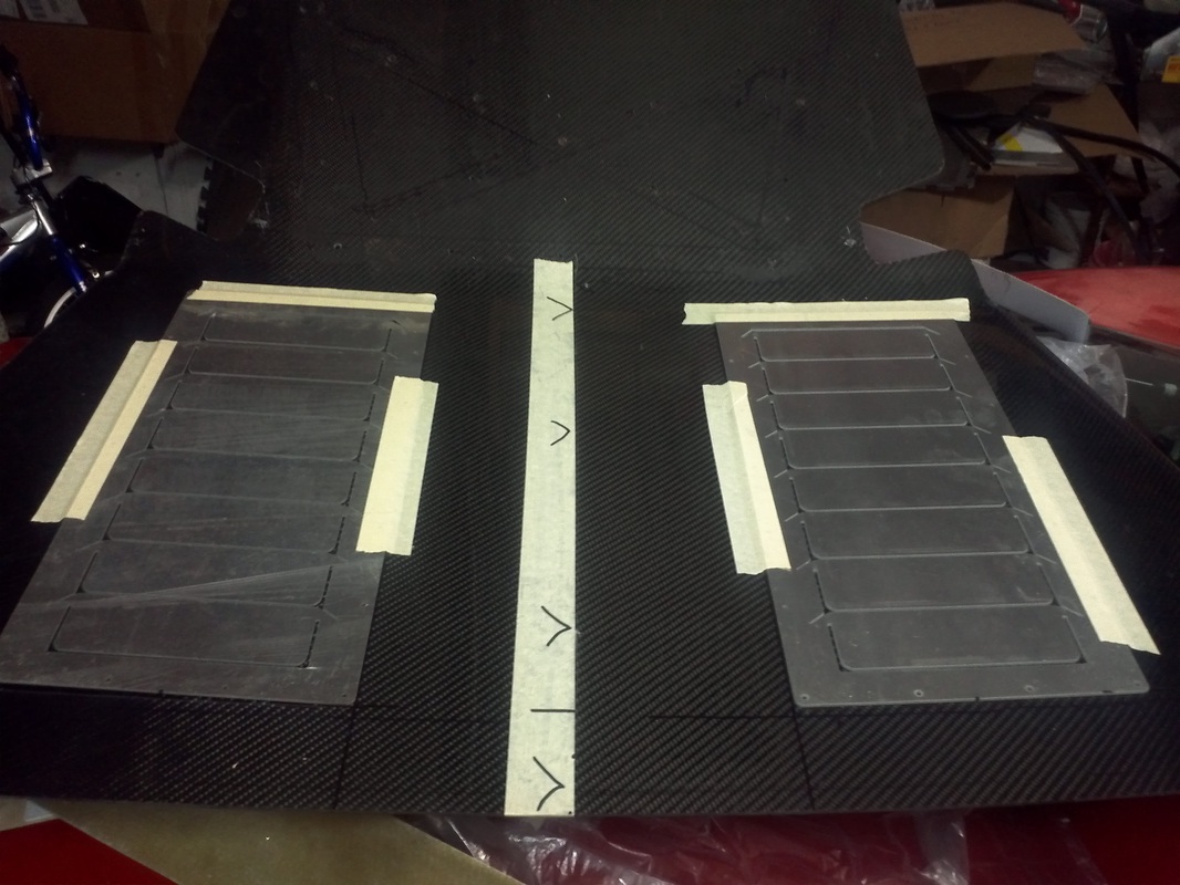
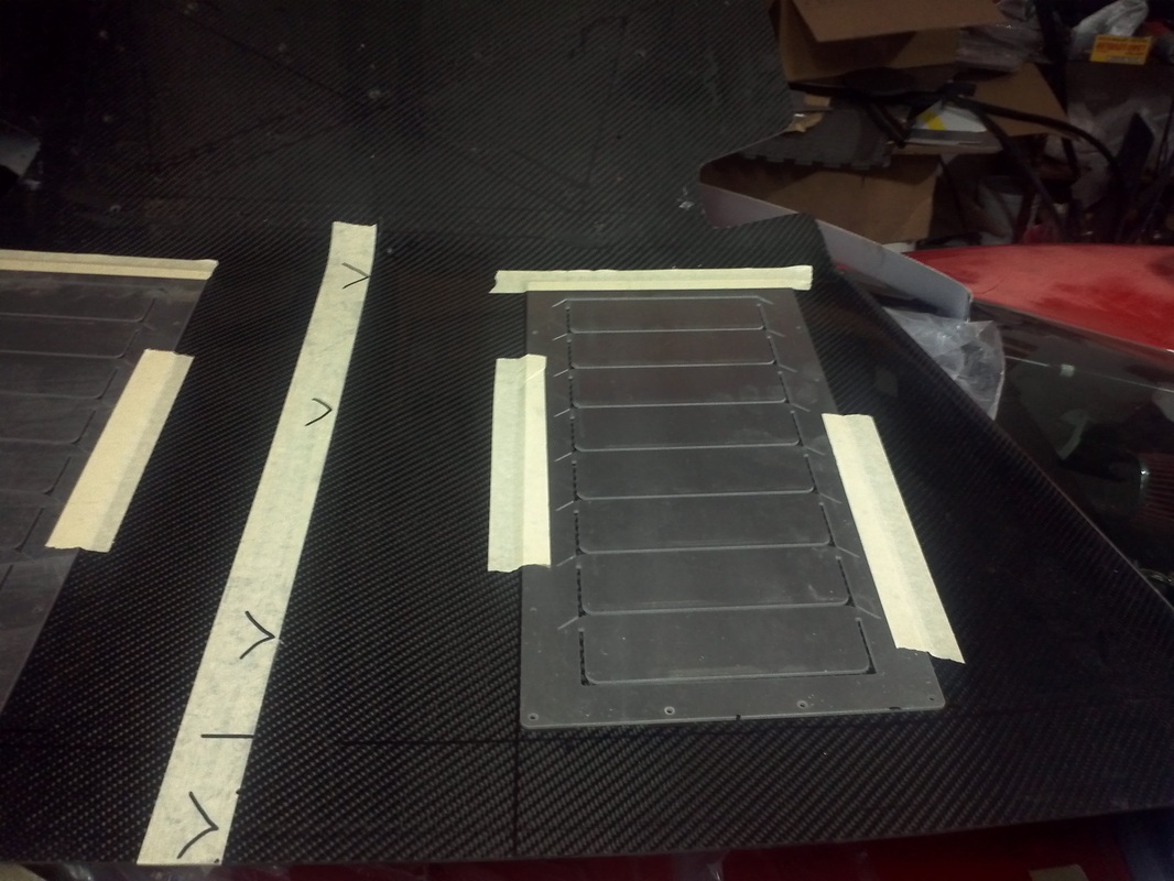
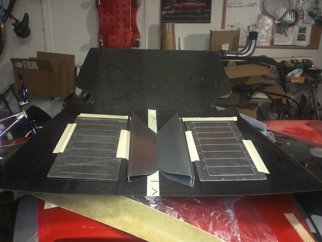
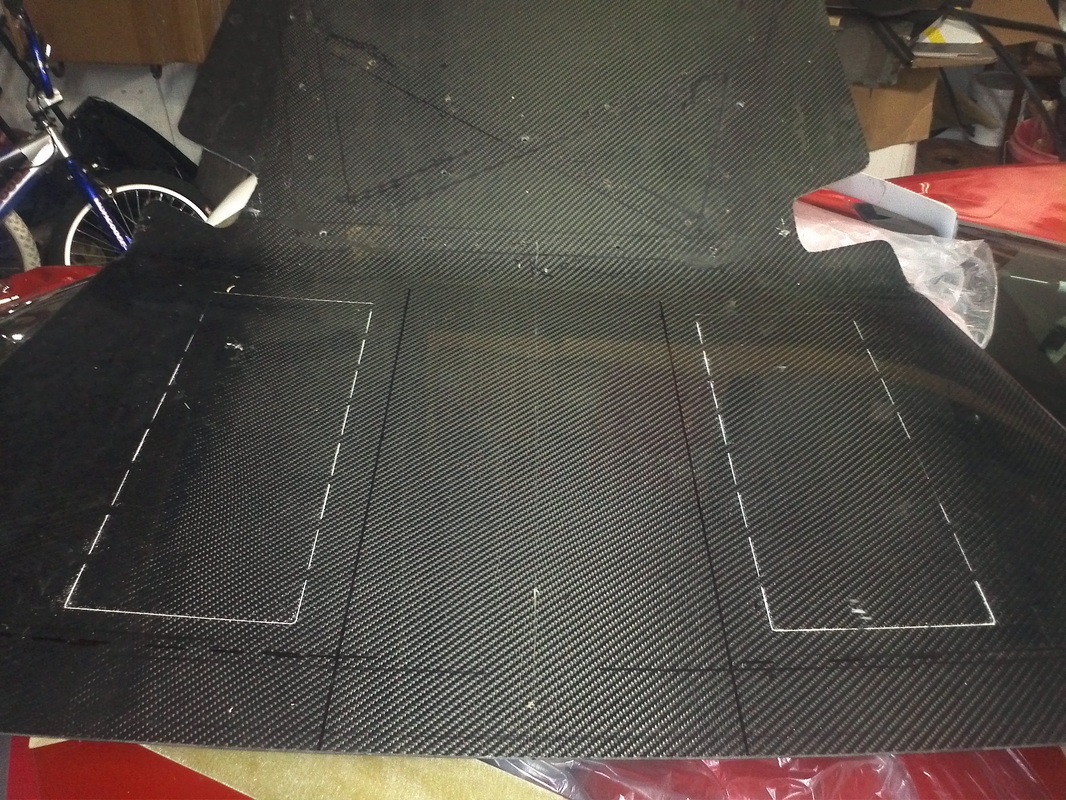
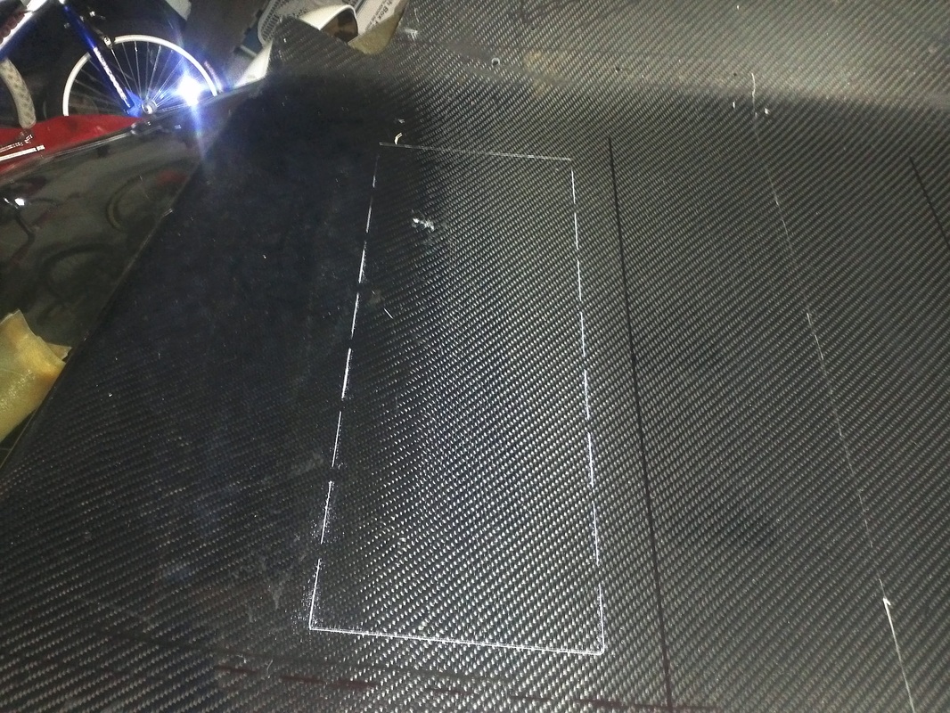
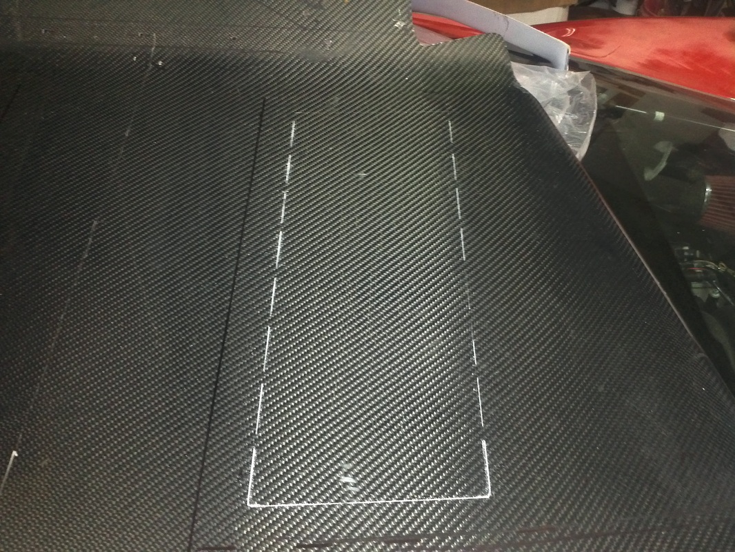
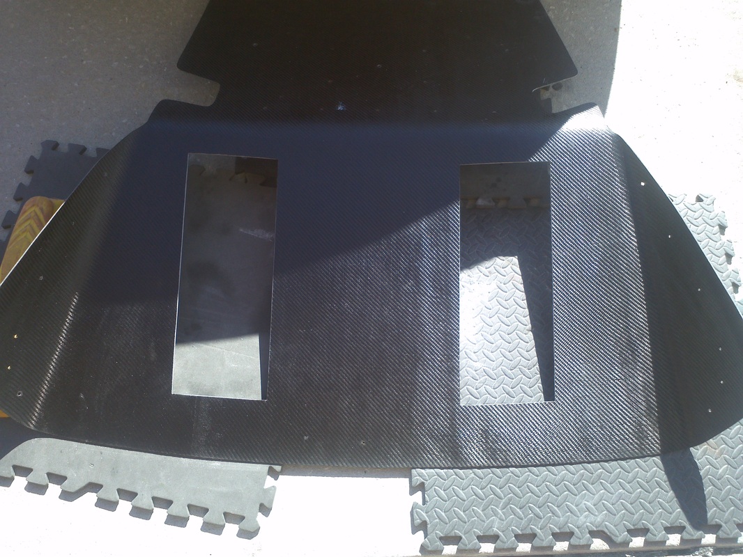
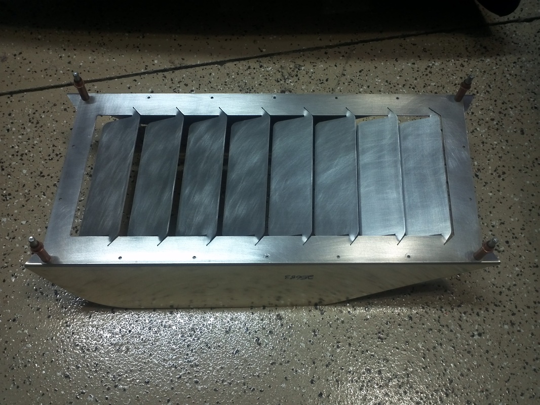
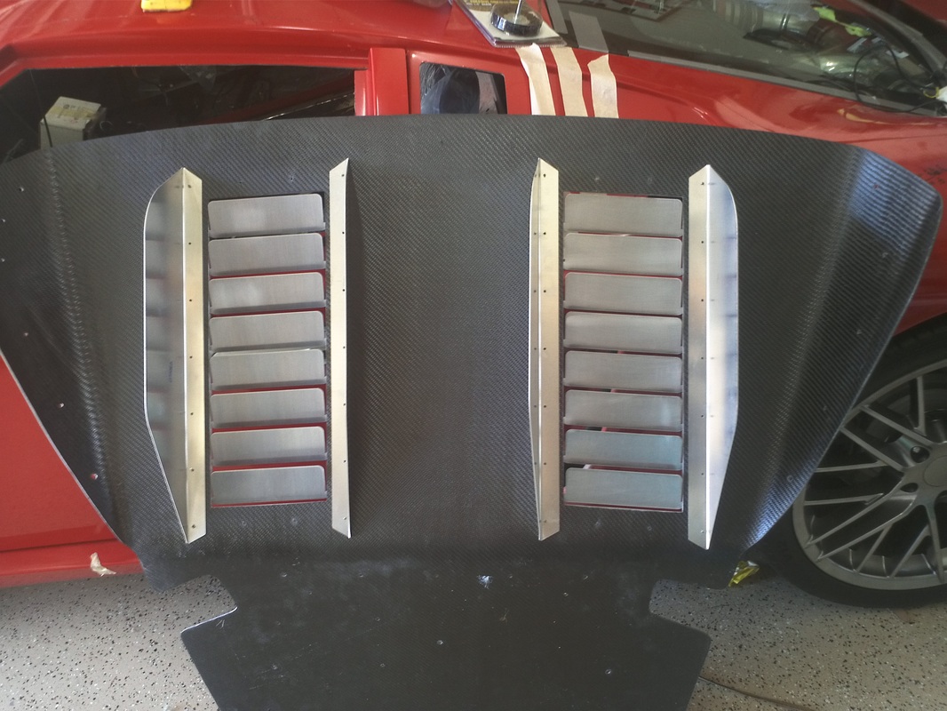
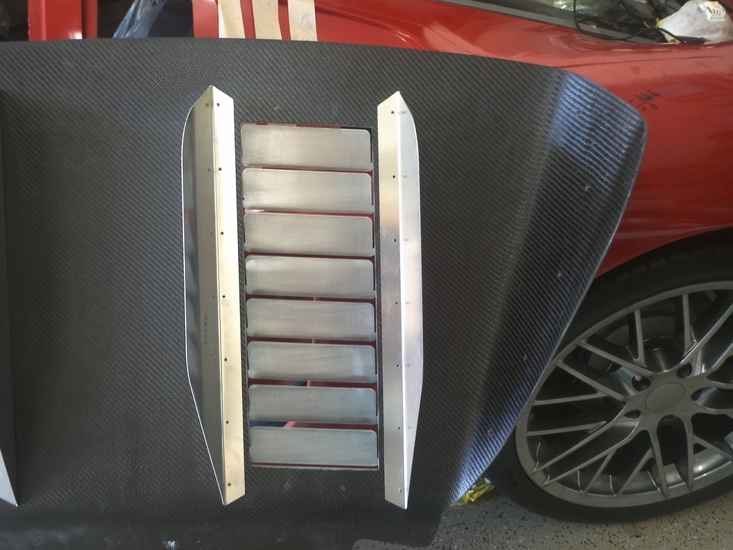
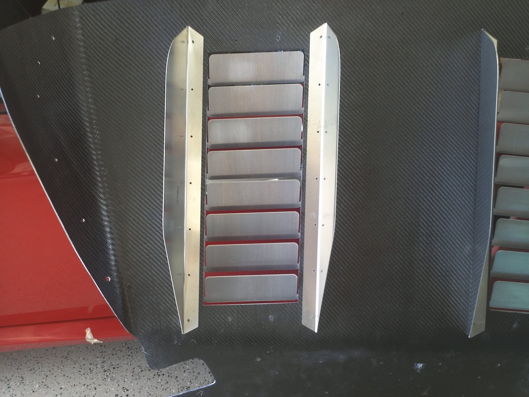
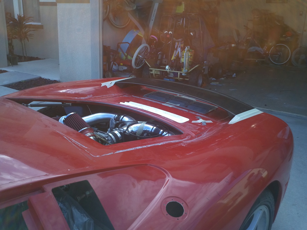
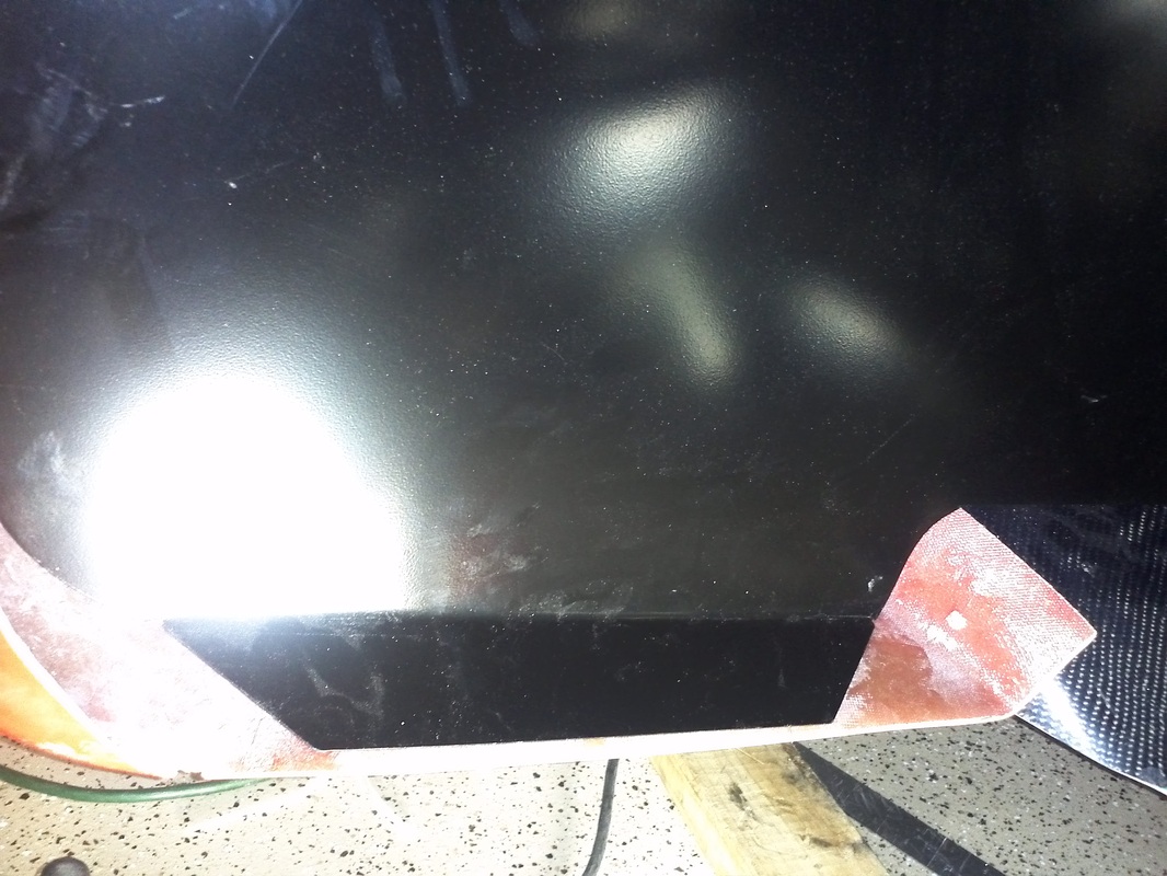
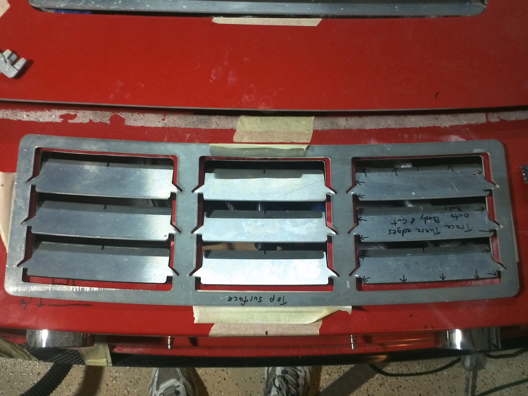
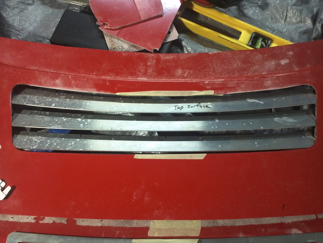
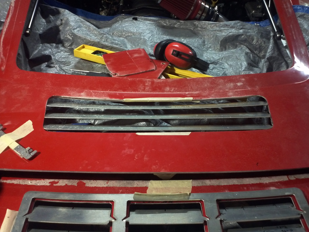
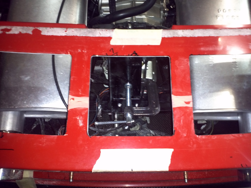
Hood Radiator Inserts
These are the radiator/ hood inserts. It has black Gel-coat on top. At first look I have questions about the airflow if the opening are made on the verticals. Definitely something I will post on the forum for input.